

Introduction: Robot Maze Solver


This tutorial will help you create an Arduino based robot that can solve basic line mazes that do not have closed loops.
How it works:
The robot is programmed to drive over the black lines of the maze and use optical sensors on the bottom of the robot to track the lines. As it travels along, the program we are using will solve the maze for the shortest path with a simple to understand method called the "Left Hand Rule" or sometimes called the "Left Hand on Wall" method.
The "Left Hand Rule" approach is to make your way through the maze, while choosing how to turn at intersections as follows:
- Always turn left if you can
- If you cannot turn left, go straight
- If you cannot turn left, or go straight, turn right
- If you cannot turn left, go straight, or turn right, turn around because you must be at a dead end
The method of solving the maze for a shorter path is by keeping track of the turns made, and reducing the list of turns as you add the latest turn to the list with known substitutions. The substitutions are three turn combinations where either (L)eft, (R)ight, or (S)traight are on either end of a (B)ack as follows:
- LBR = B
- LBS = R
- LBL = S
- SBL = R
- SBS = B
- RBL = B
For example, from the starting point:
- Start moving
- (L) eft turn is made at found intersection
- Add "L" to list
- Check if last three on list can be shortened: NO, only one turn recorded.
- (B) ack at a found dead end
- Add "B" to list
- Check if last three on list can be shortened: NO, only two turns recorded.
- (L) eft turn again when it finds the initial intersection at which it previously turned left
- Add "L" to list
- Check if last three on list can be shortened: YES.
- Replace "LBL" with "S" traight
- Continue until end point is found.
The path was shortened so it will run the solved path turns when the maze is run again from the start position. From the start, it will now drive straight through the intersection and avoid the dead end.
More about the theory behind various maze solving algorithms can be found here: https://en.wikipedia.org/wiki/Maze_solving_algorithm
The robot's program will run our example code from an Arduino compatible micro controller. If you are unfamiliar with Arduino, you can learn all about it and download the programming software at www.arduino.cc.
Step 1: Bill of Materials

Robot Components (available at www.zagrosrobotics.com) :
- Zagros Robot Starter Kit - Gobbit Version, Item# Z-8001
- USB Mini-B programming cable (see the "Item Options" add-ons at the bottom of the Robot Starter Kit page)
- Pololu QTR-8RC RC Reflectance Sensor Array
- (Optional) extra battery holders to increase the robot's voltage from 6v to as high as 12v if you want a faster or longer lasting robot.
Materials (available at Home or Office Supply):
- AA batteries (starter kit runs on 4, but you will want several extra sets or rechargeables)
- White board (inexpensive white tile or hardboard panel), poster board, or foam board. As big as you want, but probably not smaller than 22" x 28."
- Roll of black Electrical Tape
Tools:
- Pencil or dry erase marker (if using white board material)
- Tape measure
- Scissors or razor knife
- #00 Phillip screwdriver
- #1 Phillip screwdriver
- (Optional) Scratch awl
- Small Solder iron and solder
- Saw if cutting white board, or you can have it cut to size at home/builder's supply
Step 2: Design a Maze

Design a maze following these general guidelines:
- 6" grid spacing between turns and around the perimeter for a starter maze. You could have a little less around the perimeter if you are using poster board. As your robot tuning is improved, it could be possible to use a smaller grid size.
- 24" x 36" minimum board size recommended (our example is larger at 48" x 40"). However, you could make a conservative maze with a single sheet of poster board.
- The maze should be designed to have some dead ends and wrong turns possible.
- 5 tape strips wide at a minimum of 4" long for the end point.
- Unless you add smarter code than we have here, do not have any closed loops in the maze.
Step 3: Make Your Maze

Mark your board with your maze design and apply the electrical tape.
Take your time to make clean corners and straight lines.
The intersections and corners should be overlapped to avoid white gaps.
If you are using the white board material, you can easily remove sections and end points to modify your maze. It is possible to change the poster or foam board maze as well, but you will have to be careful not to damage the paper surface.
Step 4: Assemble and Wire the Robot

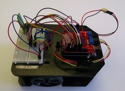
Look over your robot kit and decide how you would like to assemble it. While there are many ways possible, we have shown two examples. An enclosed wiring style with all the electronic components and wires inside, and the open and exposed version with the controller on top.
Wire the robot with the jumper wires as follows:
- Ardumoto Digital pin 2 - QTR Sensor pin1
- Ardumoto Digital pin 4 - QTR Sensor pin2
- Ardumoto Digital pin 5 - QTR Sensor pin3
- Ardumoto Digital pin 6 - QTR Sensor pin4
- Ardumoto Digital pin 7 - QTR Sensor pin5
- Ardumoto Digital pin 8 - QTR Sensor pin6
- Ardumoto Digital pin 9 - QTR Sensor pin7
- Ardumoto Digital pin 10 - QTR Sensor pin8
- Ardumoto GND - QTR Sensor pin GND
- Ardumoto 5V - QTR Sensor pin VCC
- Ardumoto Terminal A 1 - Black wire of Left motor
- Ardumoto Terminal A 2 - Red wire of Left motor
- Ardumoto Terminal B 3 - Black wire of Right motor
- Ardumoto Terminal B 4 - Red wire of Right motor
- Ardumoto Terminal VIN (+) - Positive/Red wire from battery holder
- Ardumoto Terminal VIN (-) - Negative/Black wire from battery holder
(Note: Digital Pin 3 is skipped and used by the Ardumoto motor driver. Ardumoto also uses pins 11, 12, and 13)
Step 5: Load the Maze Solving Program
This code/sketch was written and tested within Arduino 1.6.4
The sketch requires the "QTRSensors" library developed by Pololu for their QTR-8RC sensor array.
- Download the Arduino code here: GobbitMazeSolver
- Place the "GobbitMazeSolver" folder in your Arduino folder with your other programs.
- Make sure you do not have any other versions of the QTR libraries installed.
- Move the folder "QTRSensors" that is inside your "GobbitMazeSolver" folder to your "Arduino\libraries" folder. If you have trouble installing the library, you can find help here: http://arduino.cc/en/Guide/Libraries
- Open the Arduino software.
- Open "GobbitMazeSolver" sketch
- Connect your computer and the Red Board in your robot with a USB cable.
- Upload the sketch.
Step 6: Test and Tune Your Robot

While the provided sample code is not fully optimized, it should run with little or no initial adjustment. However, we made sure to leave plenty of room for improvement. When you develop a better understanding of how it all works, you may even decide to toss out a lot of our code and implement a whole new approach of your own.
The sample program has numerous variables and portions of the code commented to help you tune your robot's performance on your maze. If you have initial trouble, try these first:
- If your initial calibration sequence is over or under running the line severely and not finding the line on the last sweep, adjust the "calSpeed."
- If your robot has significant trouble over running turns, or is just plain out of control, slow down the other motor speed variables.
- The robot should wait to start turning at intersections until its wheels are over the intersection. If they are not at the right point, this could lead to excessive corrections needed in the line following which could in turn lead to steep angles of approach to following intersections or straight sections with false intersection indication. Adjust the "drivePastDelay" if the wheels are not over the intersection when it starts to turn.
To better understand the line following portion of the code, and how to optimize it, check out our earlier instructable: "Line Following Robot with Basic PD (Proportional-Derivative) Control"


