

Introduction: SCADA for Arduino-based Control Systems


Supervisory Control and Data Acquisition (SCADA) is a framework for monitoring and remotely accessing control systems commonly used in a wide range of industrial systems such as power plants, railways, manufacturing units, steel plants, airplanes and many other forms of automated industrial systems.
Step 1: Shopping for the Component List
Step 2: Setting Up the Arduino IDE

This project requires the use of certain libraries for interfacing with different ICs such as I/O expander and DAC chips. The following libraries are required and have been provided through a Github repository:
0. Go through the following libraries and install them onto the Arduino IDE using Sketch > Include Library > Add .ZIP Library. and then browse the ZIP file that is included in the Github repository below
1. State Machine Library (SM)
2. MCP492X Library
3. MCP23S17 Library
Github Repository: SCADA for Arduino-based Control Systems
Step 3: Understanding the Control System
The project essentially implements a 4-state Finite State Machine (FSM) using the State Machine Library. The four states can be described as the following:
1. NO_LED: All LEDs are in the OFF state.
2. ALL_LED: All the LEDs are in the ON state.
3. BIN_CNT: The set of 8 LEDs functions as the display of an 8-bit binary counting sequence.
4. SENSE: The state switches to ALL_LED if the Ultrasonic sensor detects an object in proximity. Otherwise, continues to count in binary just like the BIN_CNT state.
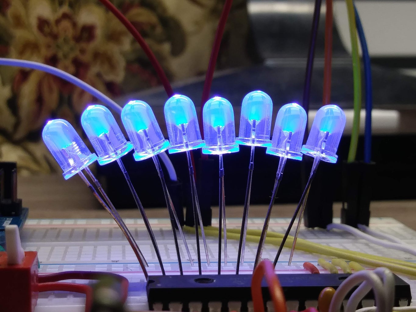
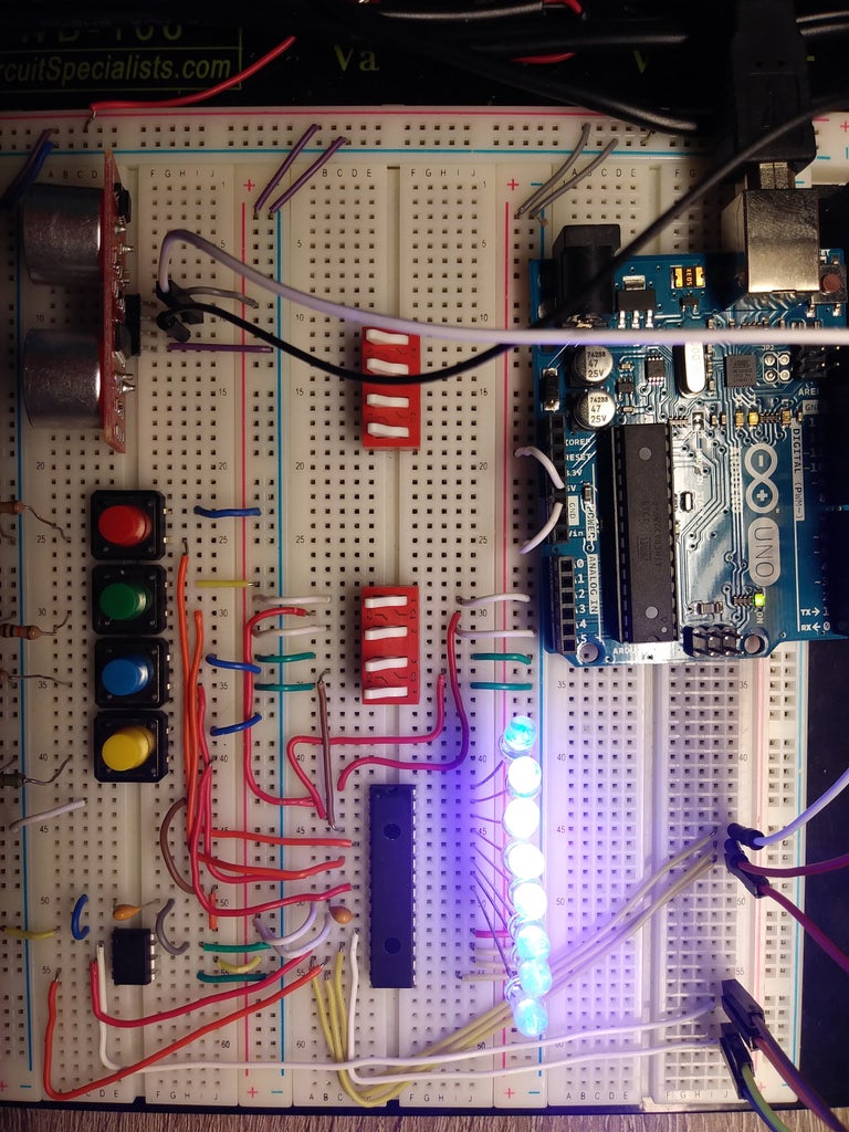
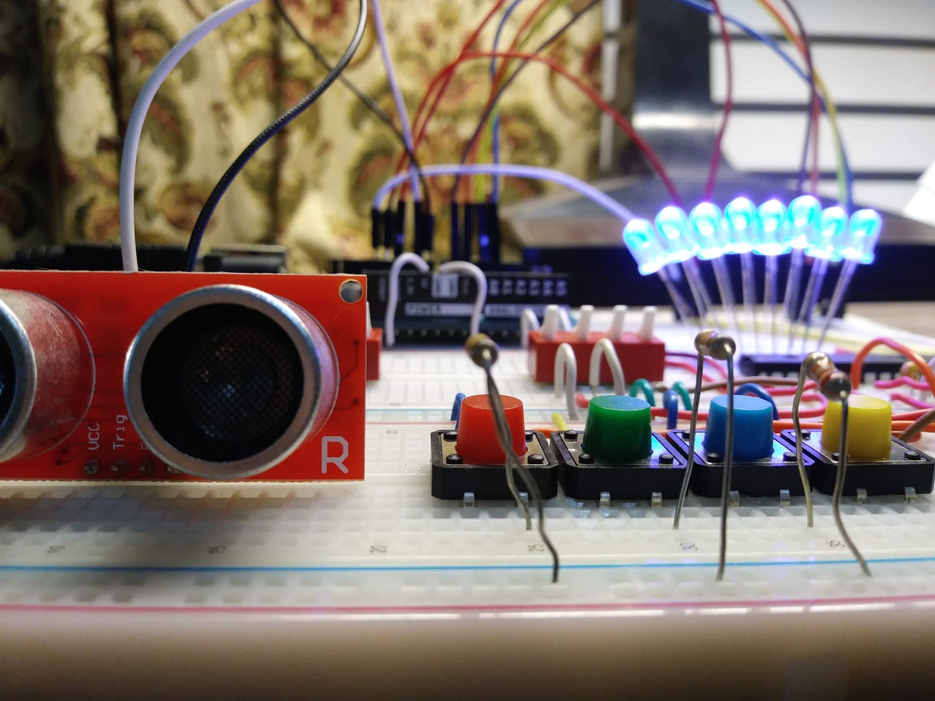
Step 4: Building the Circuit

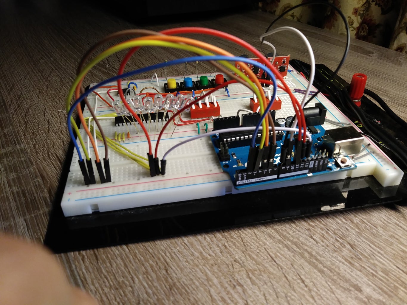
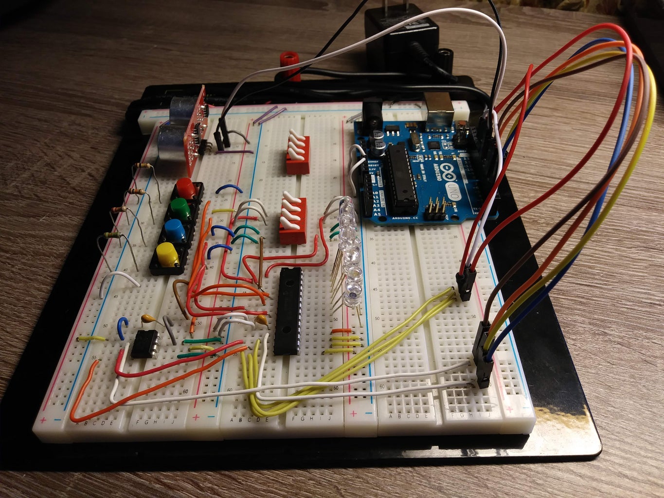
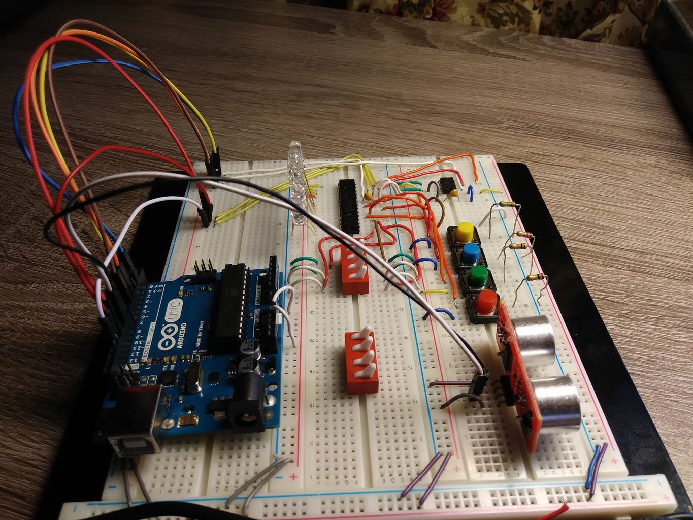
Multiple pictures have been provided taken from different angles of the Arduino Control System. Use the images as the reference to build the system.
Step 5: Uploading the Source Code to Arduino
Once the circuit has been built, the Arduino sketch provided in the SCADA.ino file in the Github repository can be uploaded to the Arduino. The State Machine can then be tested using the different push button in the circuit as shown in the video.


