

Introduction: Simple 3-8 Decoder / Demultiplexer Tutorial

This guide is intended for people new to electronics (like myself) who wants to understand how 238 decoders (demultiplexers) work. These are often used in LED-cube projects and hopefully this simple exercise will illustrate how they work.
as far as I understand decoder and demultiplexers are essentially two names for the same thing. I will use the word decoder from now on:
Components I used:
Arduino UNO
Breadboard with "rail" attached on the right side (for the ground connection)
74HC238 decoder (http://www.electrokit.com/74hc238n.43068)
5 Yellow LEDS (the cheapest I could find)
5 resistors á 150 Ohms (Brown-Green-Brown-Gold)
breadboard cables
Step 1: What Is a Decoder?
A decoder ( or demultiplexer) is a component that only needs a small number of inputs to create a larger number of outputs.
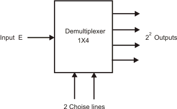
In my example I use a 238 decoder but to describe it I will first describe the 1x4 demultiplexer:
the general name for demultiplexers is 1X2n and uses 1 input and n "choice" inputs to create 2^n outputs.
The 1x4 demultiplexer therefor has 1 input, 2 "choice" inputs to select which of the 4 (2^2) outputs that should be ON/OFF (HIGH/LOW). If the input is LOW the entire demultiplexer is dead - nothing happens.
If the input is HIGH there is 4 possible combinations of the 2 selector inputs which we can call A and B respectively
(A=LOW, B=LOW)
(A=HIGH, B=LOW)
(A=HIGH, B=HIGH)
(A=LOW, B=HIGH)
As you might have guessed - by manipulating these 2 selector inputs we can control 4 outputs.
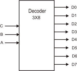
The 238 decoder (in my case the 74HC238N) uses 3 selector inputs called A0, A1 and A2 which together can make 8 possible combinations (2^3=8) and thus has 8 outputs (0,1,2,3,4,5,6 and 7).
In my tutorial I only use 5 of the outputs to turn on/off 5 LEDS. But feel free to add 3 additional LEDS if you want to.
Final note about demultiplexers/decoders: Using only 2 inputs (or more) and getting 4 outputs (or more) sounds very good doesn't it? Well it depends on what you are planning to use it for. The drawback of this component is that you can only have one of the multiple outputs HIGH (while the others are LOW) at a time. The do not work in "parallel".
It is also possible to have one of the outputs LOW while all the other are HIGH,. But you can for example not have output 2 and 4 HIGH while the rest are LOW.
Thus, In my tutorial I will only light up one LED at a time.
Step 2: 74HC238 Datasheet
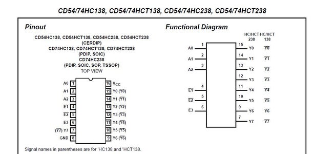

Before we build the project you should have a look at the most importaint info in the datasheet for the 74HC238N decoder:
The first picture shows all the pins: A0-A2 are selection inputs, E1-E3 are "Enable" inputs that must be set either HIGH or LOW for the decoder to work (according to the Truth-table diagram), Y0-Y7 are the 8 outputs, Vcc is the voltage input, GND is ground (not used)
The E0-E2 pins are used if you want to cascade connect several decoders in series/parallel, which I will not do here, but this is often done in larger LED-cubes - in order to get even more outputs.
The truth table shows the "rules" for the 3 selector input pins (and the "Enable" inputs, although these are constant) for turning on each of the 8 outputs. For example: if we want to turn on LED nr 1 (connected to output Y0) we should look at row nr 4 (from the top) and keep all 3 selector inputs (A0-A2) set to LOW. Also, E3 should be high while E2 and E1 are LOW.
Step 3: Setting It Up
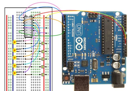
The blue "rail" on the breadboard will be connected to ground on the Arduino. Notice that the holes in this part of the breadboard are all connected vertically, unlike the rest of the board where they are connected horizontially.
Vcc should be connected to the power from the Arduino (5V)
A0 to Digital out 2
A1 to Digital out 3
A2 to digital out 4
Both E1 and E2 should be kept LOW all the time, so connect these two to the grounded rail on the breadboard.
E3 to Digital out 5. In my code I will make the Arduino digital out pin 5 HIGH all the time (as the decoder wont function otherwise). You could connect E3 to Vcc instead, as then it will also get current and be HIGH all the time.
Connect the outputs Y0-Y4 to the 5 different LEDS as shown.
The LEDS all have one shorter leg and one longer leg. Put the LEDS in the breadboard with the longer leg on top (as shown).
Connect the shorter leg via a short cable and a 150 Ohm transistor to the "ground"-rail. It doesn't matter which direction you put the resistor, it works both ways.
Step 4: The Arduino Code

Now we just need to add the code.
/*
Cycling through the 5 connected LEDS
Robert Månsson
On my decoder E1 and E2 is LOW, E3 is connected to pin5 (High)
*/
const int selA0 = 2;
const int selA1 = 3;
const int selA2 = 4;
const int E3 = 5;
void setup()
{
// initialize the control outputs
pinMode(selA0, OUTPUT);
pinMode(selA1, OUTPUT);
pinMode(selA2, OUTPUT);
digitalWrite(selA0, LOW);
digitalWrite(selA1, LOW);
digitalWrite(selA2, LOW);
digitalWrite(E3, HIGH);
}
void loop()
{
/*turn on LED 1 */
digitalWrite(selA0, LOW);
digitalWrite(selA1, LOW);
digitalWrite(selA2, LOW);
delay(1000);
/*turn on LED 2 */
digitalWrite(selA0, HIGH);
digitalWrite(selA1, LOW);
digitalWrite(selA2, LOW);
delay(1000);
/*turn on LED 3 */
digitalWrite(selA0, LOW);
digitalWrite(selA1, HIGH);
digitalWrite(selA2, LOW);
delay(1000);
/*turn on LED 4 */
digitalWrite(selA0, HIGH);
digitalWrite(selA1, HIGH);
digitalWrite(selA2, LOW);
delay(1000);
/*turn on LED 4 */
digitalWrite(selA0, LOW);
digitalWrite(selA1, LOW);
digitalWrite(selA2, HIGH);
delay(1000);
}


