

Introduction: Servo Controller for a 4 Axis Robot Using a 3 Button Control System (updated)


In this instructable, I will show you how to control a 4 axis robot arm using only 3 buttons (switches)
A quick breakdown of what everything does:
Button S1 - Pressing this will let you select the servo motor you want to move
Buttons S2 and S3 - These two buttons control the direction of movement of the servo motor
LEDs 1 2 3 and 4 - The 4 LEDs show which servo motor has been selected
Step 1: What You Need to Build the Circuit


1 x Arduino Nano
1 x breadboard
1 x 4 x AA battery pack (Please note: a single 9v battery will not work!)
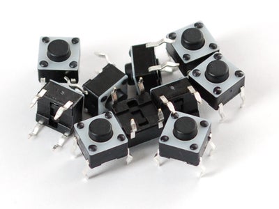
3 x Momentary Push Buttons
4 x Coloured LEDs
3 x 10,000 Ohm resistors (Brown Black Orange)
4 x 330 Ohm resistors (Orange Orange Brown)
1 x 40 pack of male/male jumper cables
4 x Servo motors - I used MG90D in this project
The total cost of the project: @ $70
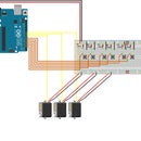
Step 2: Installing the Arduino Nano and Arranging the Power on the Breadboard

Insert the Arduino Nano into the breadboard as shown in the diagram.
Note: The legs are quite stiff so you might want to bend them just a little bit on a flat surface
Setting up the power lines to the breadboard
- The servo motors will get their power from the 4 x AA battery pack
- The pushbuttons and LEDs will be powered by the Arduino's 5v line
- Ground will be shared between the Arduino and the battery pack.
Note 1: The Arduino doesn't output enough power to run all 4 servos and you risk damaging it if you try running all of them from the Arduino's 5v line.
Note 2: I have tied the Arduino ground into the battery ground to help stabilize the circuit, this is an important step, don't miss it.
Step 3: Installing the Push Buttons

First let's remove the battery from the circuit so we don't zap anything by mistake
(We can put it back once we have everything hooked up and have checked for mistakes.)
Connecting up the S1 button
- Take a 10k resistor, push one end into the 5v power line and connect the other end of the resistor to one side of the button
- Take a jumper cable, plug one end into the same line as the resistor (see diagram)
- Take the other end of the cable and plug it into D2
- Connect the other side of the button to ground
Buttons S2 and S2 are setup in the same way
- S2 plug the jumper cable into d3
- S3 plug the jumper cable into d4
Connection Summary:
- S1 is the button we will use to select a servo and is connected to D2 on the Arduino.
- S2 will move the servo left and is connected to D3 on the Arduino.
- S3 will move the servo right and is connected to D4 on the Arduino.
Read this page for more info on pull up resistors: https://learn.sparkfun.com/tutorials/pull-up-resi...
Step 4: Installing the LEDs and Their Resistors

Identifying which side of an LED is positive or negative
Method 1:
An LED has a long leg and a short leg
- The long leg is the positive
- The short leg is negative.
Method 2
- If you look carefully at the head of the LED you will see there are two pieces of metal - one small and one big, The small piece of metal shows the POSITIVE side
Connecting LED 1 to the circuit
- Push the two legs of the LED into the breadboard and connect the short leg to ground with a jumper cable
- Connect a 330 Ohm resistor to the positive leg of the LED
- A jumper cable then connects from the resistor to D9 on the Arduino (see the diagram.)
- The other LEDs are connected in the same way, see below for where the cables plug into the Arduino
Connection Summary:
- The jumper cable from LED 1 connects to D9 on the Arduino.
- The jumper cable from LED 2 connects to D10 on the Arduino.
- The jumper cable from LED 3 connects to D11 on the Arduino.
- The jumper cable from LED 4 connects to D12 on the Arduino.
Note:
- Resistors protect LEDs, dont forget to use them, or you can break the LED
- The function of the LEDs is to show which servo motor is currently selected.
Step 5: Installing the Servo Motors


A few notes on Servo Motors:
Servo motors have 3 cables connected to them.
- A positive, a negative and a signal.
- The colour code for servo cables is tricky because there are several different color combinations
- Look at the picture I include for the most common colour combinations.
In my diagram, the servo has a red, a black and a yellow cable.
- Red is positive
- Black is negative (ground)
- Yellow is signal
Connecting the Servos to the circuit:
- Connect a jumper cable from black on the servo to the battery ground on the breadboard
- Connect a jumper cable from Red to the positive line of the battery
- Connect a jumper cable from the yellow signal to D5 on the Arduino
- The rest of the servos are connected in exactly the same way, except where the yellow signal cable goes
Connection Summary:
- Servo 1 signal cable connects to D5
- Servo 2 signal cable connects to D6
- Servo 3 signal cable connects to D7
- Servo 4 signal cable connects to D8
Once that is all done, we have finished the physical set up and are ready to get on with the programming.
Step 6: The Program Part 1

Connect and run the program with servo motors connected BEFORE building the robot
The first thing the program does is set all 4 servos to the middle of their arc of movement.
If you build the robot before you do this, it might not be able to move in the way you want
The program - Step by Step
Pressing S1
- The Arduino detects this button press
- It lights up the first LED
- It activates S2 and S3 - the movement buttons
- It activates servo motor 1.
After you have pressed S1
Pressing S2 or S3 sends a signal to the arduino,
- a calculation is performed and the servo motor moves left one degree for S2, or right if you press S3
- It will do this every time you press the movement button until the servo's maximum or minimum movement angle is reached.
- Pressing S1 AGAIN makes the next LED light up and servo 2 becomes active and so on
- Once you have selected servo 4, pressing S1 again causes servo 1 to become selected and so the program loops back
Step 7: The Program: 2
Here is the program needed to run the circuit, I also include it as a downloadable file
#include <Servo.h> // Allows the Arduino to easily control servo motors
Servo myservo1; // create servo objects to control 4 servos
Servo myservo2;
Servo myservo3;
Servo myservo4;
int pos1 = 85; // variable to store the servo's position, set start position to 85
int pos2 = 85; // Basically creates a default starting position for the robot limbs
int pos3 = 85;
int pos4 = 85;
int leftPressed = 0; // Variables which will help us control the movement of the robot
int rightPressed = 0;
const int maxDeg = 173; // variable that limits the maximum range of the servo's movement to 175
const int minDeg = 7; // variable that limits the minimum range of the servo's movement to 5
const int movement = 2; // variable which sets the default distance to move the servo
const int switchPin = 2; // the button that controls the servo selection is connected to pin 2
const int leftButton = 3; // the 2 buttons which control the left and right movement of the servo
const int rightButton = 4;
const int servoOutput1 = 5; // tells the Arduino the location of the signal cables connected to the servos
const int servoOutput2 = 6;
const int servoOutput3 = 7;
const int servoOutput4 = 8;
byte ledPin1 = 9; // led on pin 9
byte ledPin2 = 10; // led on pin 10
byte ledPin3 = 11; // led on pin 11
byte ledPin4 = 12; // led on pin 12
byte buttonPresses = 0; // how many times the button has been pressed
byte lastPressCount = 0; // to keep track of last press count
void setup() {
pinMode(ledPin1, OUTPUT); // set the digital pins to the LEDs as outputs
pinMode(ledPin2, OUTPUT);
pinMode(ledPin3, OUTPUT);
pinMode(ledPin4, OUTPUT);
pinMode(switchPin, INPUT); // set the servo select button as an input
pinMode(servoOutput1, OUTPUT); // set the pins connected to the servos as outputs
pinMode(servoOutput2, OUTPUT);
pinMode(servoOutput3, OUTPUT);
pinMode(servoOutput4, OUTPUT);
pinMode(leftButton, INPUT); // set the left and right control buttons as inputs
pinMode(rightButton, INPUT);
myservo1.attach(servoOutput1); // attaches the servo's signal cable location to the servo object
myservo2.attach(servoOutput2);
myservo3.attach(servoOutput3);
myservo4.attach(servoOutput4);
Serial.begin(9600); // set up serial communication at 9600bps
}
void loop() {
leftPressed = digitalRead(leftButton); // gives a value to the variables as the state of the switch
rightPressed = digitalRead(rightButton);
if (digitalRead(switchPin) == HIGH){
Serial.print ("Button press count = "); // out to serial
buttonPresses++;
Serial.println(buttonPresses, DEC);
delay(250);
}
if (buttonPresses == 1){
delay(30);
digitalWrite(ledPin1, HIGH);
digitalWrite(ledPin2, LOW);
digitalWrite(ledPin3, LOW);
digitalWrite(ledPin4, LOW);
if(leftPressed){
if(pos1 < minDeg){
pos1 = minDeg;
delay(30);
myservo1.write(pos1); // tells the servo to go to the position stored in the variable ‘pos’
Serial.print ("Servo position: ");
Serial.println(pos1,DEC);
}
if(pos1 < maxDeg){
pos1 -= movement;
delay(30);
myservo1.write(pos1); // tells the servo to go to the position stored in the variable ‘pos’
Serial.print ("Servo position: ");
Serial.println(pos1,DEC);
}
}
if(rightPressed){
if(pos1 > maxDeg){
pos1 = maxDeg;
delay(30);
myservo1.write(pos1); // tells the servo to go to the position stored in the variable ‘pos’
Serial.print ("Servo position: ");
Serial.println(pos1,DEC);
}
if(pos1 > minDeg){
pos1 += movement;
delay(30);
myservo1.write(pos1); // tells the servo to go to the position stored in the variable ‘pos’
Serial.print ("Servo position: ");
Serial.println(pos1,DEC);
}
}
}
if (buttonPresses == 2){
digitalWrite(ledPin1, LOW);
digitalWrite(ledPin2, HIGH);
digitalWrite(ledPin3, LOW);
digitalWrite(ledPin4, LOW);
if(leftPressed){
if(pos2 < minDeg){
pos2 = minDeg;
delay(30);
myservo2.write(pos2); // tells the servo to go to the position stored in the variable ‘pos’
Serial.print ("Servo position: ");
Serial.println(pos2,DEC);
}
if(pos2 < maxDeg){
pos2 -= movement;
delay(30);
myservo2.write(pos2); // tells the servo to go to the position stored in the variable ‘pos’
Serial.print ("Servo position: ");
Serial.println(pos2,DEC);
}
}
if(rightPressed){
if(pos2 > maxDeg){
pos2 = maxDeg;
delay(30);
myservo2.write(pos2); // tells the servo to go to the position stored in the variable ‘pos’
Serial.print ("Servo position: ");
Serial.println(pos2,DEC);
}
if(pos2 > minDeg){
pos2 += movement;
delay(30);
myservo2.write(pos2); // tells the servo to go to the position stored in the variable ‘pos’
Serial.print ("Servo position: ");
Serial.println(pos1,DEC);
}
}
}
if (buttonPresses == 3){
digitalWrite(ledPin1, LOW);
digitalWrite(ledPin2, LOW);
digitalWrite(ledPin3, HIGH);
digitalWrite(ledPin4, LOW);
if(leftPressed){
if(pos3 < maxDeg){
pos3 += movement;
delay(30);
myservo3.write(pos3);
Serial.print ("Servo position: ");
Serial.println(pos3,DEC);
}
}
if(rightPressed){
if(pos3 > minDeg){
pos3 -= movement;
delay(30);
myservo3.write(pos3);
Serial.print ("Servo position: ");
Serial.println(pos3,DEC);
}
}
}
if (buttonPresses == 4){
digitalWrite(ledPin1, LOW);
digitalWrite(ledPin2, LOW);
digitalWrite(ledPin3, LOW);
digitalWrite(ledPin4, HIGH);
if(leftPressed){
if(pos4 < maxDeg){
pos4 += movement;
delay(30);
myservo4.write(pos4);
Serial.print ("Servo position: ");
Serial.println(pos4,DEC);
}
}
if(rightPressed){
if(pos4 > minDeg){
pos4 -= movement;
delay(30);
myservo4.write(pos4);
Serial.print ("Servo position: ");
Serial.println(pos4,DEC);
}
}
}
if (buttonPresses == 5) {
buttonPresses = 1;
}
if (lastPressCount != buttonPresses){ // only do output if the count has changed
Serial.print ("Servo Selected = "); // out to serial
Serial.println(buttonPresses, DEC);
Serial.print ("Servo1 position: ");
Serial.println(pos1,DEC);
Serial.print ("Servo2 position: ");
Serial.println(pos2,DEC);
Serial.print ("Servo3 position: ");
Serial.println(pos3,DEC);
Serial.print ("Servo4 position: ");
Serial.println(pos4,DEC);
lastPressCount = buttonPresses; }
}
Important note:
If you plan on using this control system on a robot arm please read the designers notes on how to set up the initial servo positions and adjust the code above to best position the arms


