

Introduction: Simple Arduino LoRa Communciation (5km and More)


We are going to test E32-TTL-100 with my library. It is a wireless transceiver module, operates at 410 441 MHz (or 868MHz or 915MHz) based on original RFIC SX1278 from SEMTECH, transparent transmission is available, TTL level. The module adopts LORA spread spectrum technology.
Supplies
Step 1: Devices Specs
- Module size: 21*36mm
- Antenna type: SMA-K (50Ω impedance)
- Transmission distance: 3000m(max)
- Maximum power: 2dB(100mW)
- Air rates: 2.4Kbps (6 optional level (0.3, 1.2, 2.4, 4.8, 9.6, 19.2kbps)
- Emission length: 512ByteReceive
- length: 512Byte
- Communication Interface: UART – 8N1, 8E1, 8O1,
- Eight kinds of UART baud Rate, from 1200 to 115200bps (Default: 9600)
- RSSI support: No (Built-in intelligent processing)
Step 2: Transmission Type
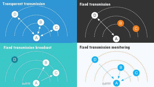
Transparent transmission
This can be considered like a “Demo mode”, by default you can send message to all device of same configured address and channel.
Fixed transmission
This type of transmission you can specify an address and a channel where where you want send the message. You can send message to a:
- Specified device with a predeterminated Address Low, Address High and Channel.
- Broadcast message to a set of channel devices Normal mode Simply send message.
Step 3: Device Mode
Normal mode
Simply send message.
Wake-up mode and power-saving mode
As you can intend if a device is in Wake-up mode can “wake” one or more devices that are in power-saving mode with a preamble communication.
Program/sleep mode
With this configuration you can change configuration of your device.
Step 4: Wiring Device


Here the schema of connection of the device, this is a fully connected, with management of M0 and M1 pin permit to change modality of the device, so you can switch to configuration or wake up mode with program, the library help you in all this operation.
Step 5: Configuration
Exist a specified command to set and get configuration
void setup() {Serial.begin(9600);delay(500);// Startup all pins and UARTe32ttl100.begin();ResponseStructContainer c;c = e32ttl100.getConfiguration();// It's important get configuration pointer before all other operationConfiguration configuration = *(Configuration*) c.data;Serial.println(c.status.getResponseDescription());Serial.println(c.status.code);printParameters(configuration);ResponseStructContainer cMi;cMi = e32ttl100.getModuleInformation();// It's important get information pointer before all other operationModuleInformation mi = *(ModuleInformation*)cMi.data;Serial.println(cMi.status.getResponseDescription());Serial.println(cMi.status.code);printModuleInformation(mi);}
Step 6: Configuration Result
And the result become
BeginSuccess1----------------------------------------HEAD BIN: 11000000 192 C0AddH BIN: 0AddL BIN: 0Chan BIN: 23 -> 433MHzSpeedParityBit BIN : 0 -> 8N1 (Default)SpeedUARTDataRate BIN : 11 -> 9600bps (default)SpeedAirDataRate BIN : 10 -> 2.4kbps (default)OptionTrans BIN : 0 -> Transparent transmission (default)OptionPullup BIN : 1 -> TXD, RXD, AUX are push-pulls/pull-upsOptionWakeup BIN : 0 -> 250ms (default)OptionFEC BIN : 1 -> Turn on Forward Error Correction Switch (Default)OptionPower BIN : 0 -> 20dBm (Default)----------------------------------------Success1----------------------------------------HEAD BIN: 11000011 195 C3Model no.: 32Version : 44Features : 14----------------------------------------
Step 7: Send Message

Here a simple sketch to send a message to all device attached to the channel
void loop() {// If something availableif (e32ttl100.available()>1) {// read the String messageResponseContainer rc = e32ttl100.receiveMessage();// Is something goes wrong print errorif (rc.status.code!=1){rc.status.getResponseDescription();}else{// Print the data receivedSerial.println(rc.data);}}if (Serial.available()) {String input = Serial.readString();e32ttl100.sendMessage(input);}}
Step 8: Shield for Arduino

I create also a shield for Arduino that become very usefully for prototyping.
And I release It as open source project here
https://www.pcbway.com/project/shareproject/LoRa_E32_Series_device_Arduino_shield.html
Step 9: Library


Participated in the
Arduino Contest 2020


