Introduction: Smart Extension Box With ESP-NOW Protocol


In the previous Instructable we saw how to implement a gesture detection algorithm for our esp8266 based fitness watch, Where we were able to detect different hand gestures and display them on the OLED screen. In this Instructable we’ll take that gesture detection feature one step ahead and also make a complimentary hardware called "Smart Extension Box" which will let us control multiple home appliance devices connected to it with our watch. Get the below supplies and let's the build!
Supplies
These are the list of products which can help you do this project with ease
(Affiliate Link)
- Esp12E: https://amzn.to/3h3b37s
- OLED display: https://amzn.to/2VcEATc
- MPU6050: https://amzn.to/2J8E06T
- Haptic motor(exact one): https://amzn.to/2J8E06T
- Haptic motor(alternative): https://amzn.to/2J8E06T
- 3.3V regulator: https://amzn.to/2J8E06T
- 105mah battery: https://amzn.to/2J8E06T
- Velcro: https://amzn.to/2J8E06T
- Header Pins: https://amzn.to/2J8E06T
- Angled Header Pins: https://amzn.to/2J8E06T
- Wires: https://amzn.to/2J8E06T
- FTDI: https://amzn.to/2J8E06T
- Male USB: https://amzn.to/2J8E06T
- PCB: https://amzn.to/2J8E06T
- Soldering Gun: https://amzn.to/2J8E06T
- Soldering Lead: https://amzn.to/2J8E06T
- Foam sheets: https://amzn.to/2J8E06T
- Hi-link: https://amzn.to/3dsAQHM
- Extension Box: https://amzn.to/3sf2pZ4
- Relay 5V : https://amzn.to/37zvCpK
- screw terminal: https://amzn.to/3qHwVKP
- Transistor: https://amzn.to/3kcfrnE
- Diode : https://amzn.to/3kdewTJ
- Resistor : https://amzn.to/2ZCruRu
Step 1: ESP NOW


It’s a proprietary protocol by Espressif. It’s a very clever little protocol where data is transferred from one to another without actually making a connection between each other. It sounds confusing but here me out.
Unlike bluetooth or wifi it doesn’t need any pairing or handshake to establish a connection between devices. Instead it uses something called a vendor action frame to transfer data. You can check their official documentation to know more about how it works.
Because I’m more interested in the advantages and limitations of this ESP NOW protocol, so we’ll have a better understanding why we are using this in our project.
Step 2: Why ESP NOW
Limitations
One of the big downside to this protocol will be, it can transfer only 250Byets of data at once so the transfer data is quite limited when compared to WiFi, bluetooth or LORA. Since it’s not making any sort of connection like wifi, it cannot access the Internet to get any additional information and Finally only 20 devices can be connected to one master device.
Advantages
Even though the data and devices are limited. In our case it should be good for just transferring ON and OFF signals. Because the protocol has other upsides like, it doesn't need any router or DHCP server so it can be used anywhere just by using 2 ESP device and it doesn't take much time to pair or connect to another device, So data can be transferred in very less time, and the device can go to sleep to save power after the data is transferred.
Step 3: Different Modes of ESP NOW


There are three modes in ESP-NOW protocol, Controller mode which can only send data, Slave mode which can receive only data and finally combo mode which can send as well as receive data. For our purpose we just need to send the data from the watch, so we can use controller mode for the watch and for the home appliance device we’ll use the slave mode. Because we are not going to send any data back from the home appliance to the watch.
Step 4: Finding MAC Address of ESP8266


But before implementing ESP-NOW protocol we need something called MAC address, This is a special address assigned by the manufacturer. In our case all ESP8266/ESP32 based development boards will have a unique address so we can identify each one of them in a network where they communicate.
Usually these MAC addresses [example : 00:0a:95:9d:68:16] are six groups of two hexadecimal digits, separated by hyphens, colons, or just by a space. It’s pretty easy to get this from esp8266. All you need is the esp8266wifi library, then use the WiFi.macAddress() function to print the mac address on the serial monitor.
//Reset the NodeMCU/esp8266 once you open the serial monitor

#include <ESP8266WiFi.h>
#include<esp8266wifi.h>

void setup(){
  Serial.begin(115200);
  Serial.println();
  Serial.print("ESP8266 Board MAC Address:  ");
  Serial.println(WiFi.macAddress());
}
void loop(){}
Just compile and upload the sketch for generic esp8266. Once the uploading is done, Open the serial monitor and reset the NodeMCU. Here you get the hex values of the mac address. Make sure you note this down, because we’ll be needing this while implementing the ESP-NOW protocol.
Step 5: How to View ESP NOW Data

Now Let’s see how to implement a simple version of ESP-NOW using two NodeMCU boards. Make sure to use the NodeMCU with a known MAC address as the slave device because the controller needs the slave MAC address to send the data.
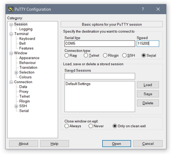
If we use just 2 NodeMCU without any additional circuit to test ESP NOW protocol it would be difficult to monitor the transmission of data and it’s status using Arduino IDE alone. So, if you want to see the data on both controller and slave simultaneously, you can either use 2 different computers, or a single computer with a software like Putty to see the serial data of one device and use Arduino IDE to see the serial data of another device. By this you can monitor both slave and master simultaneously.
Step 6: Building the Slave Device


To remove the complication from last step and make it more understandable we’ll build a simple circuit with LED’s, so instead of seeing the serial data we can see the lights turn on and turn off depending on the type of data it’s receiving from the controller.
The circuit is pretty simple, place the NodeMCU on a breadboard and connect different colour LEDs to pin D1,D2,D6 and D5 of the NodeMCU using a 470 ohm resistor and make sure all cathodes of the LEDs are connected to ground.
Now open the Esp_now_reciever.ino file in your Arduino IDE. (All the necessary files required code file for this instructable along with the circuit diagram can be downloaded from my Github repository)
In this code, we will receive the data from the controller and change the pin status so we can drive the pins high and low according to the incoming data.
(Here I have mentioned relayStatus because later we'll use the same code to drive the relay)
int relayStatus_1 = 0;<br>int relayStatus_2 = 0;
int relayStatus_3 = 0;
int relayStatus_4 = 0;
There are few things to keep in mind if you are making any modification or writing your own code. Make sure the structure in both controller and the slave are exactly the same in terms of the datatypes used and the number of data it has.
typedef struct message {<br>    int relay1;
    int relay2;
    int relay3;
    int relay4;
} message;
One more important point is make sure you disconnect from WiFi in the setup function, because the esp-now protocol doesn’t work along with WiFi connected to access point.
WiFi.disconnect();
Other than these 2 points rest of the code should be as usual. To test we’ll Just compile and upload code the Esp_now_reciever code.
Also don't forget to add a additional breadboard power supply to this circuit so it can work independently without connecting to a PC.
Attachments

Step 7: Building the Controller Device


For the controller device we just need one NodeMCU and that’s it! Open the Esp_now_Sender.ino file in your Arduino IDE. You see here I have matched the structure as well as disconnected from WiFi in the setup function.
[Note: Name of the data inside struct can be different, but number of data and it's data types should be same as esp_now_receiver]
typedef struct struct_message {<br> int relay1;
int relay2;
int relay3;
int relay4;
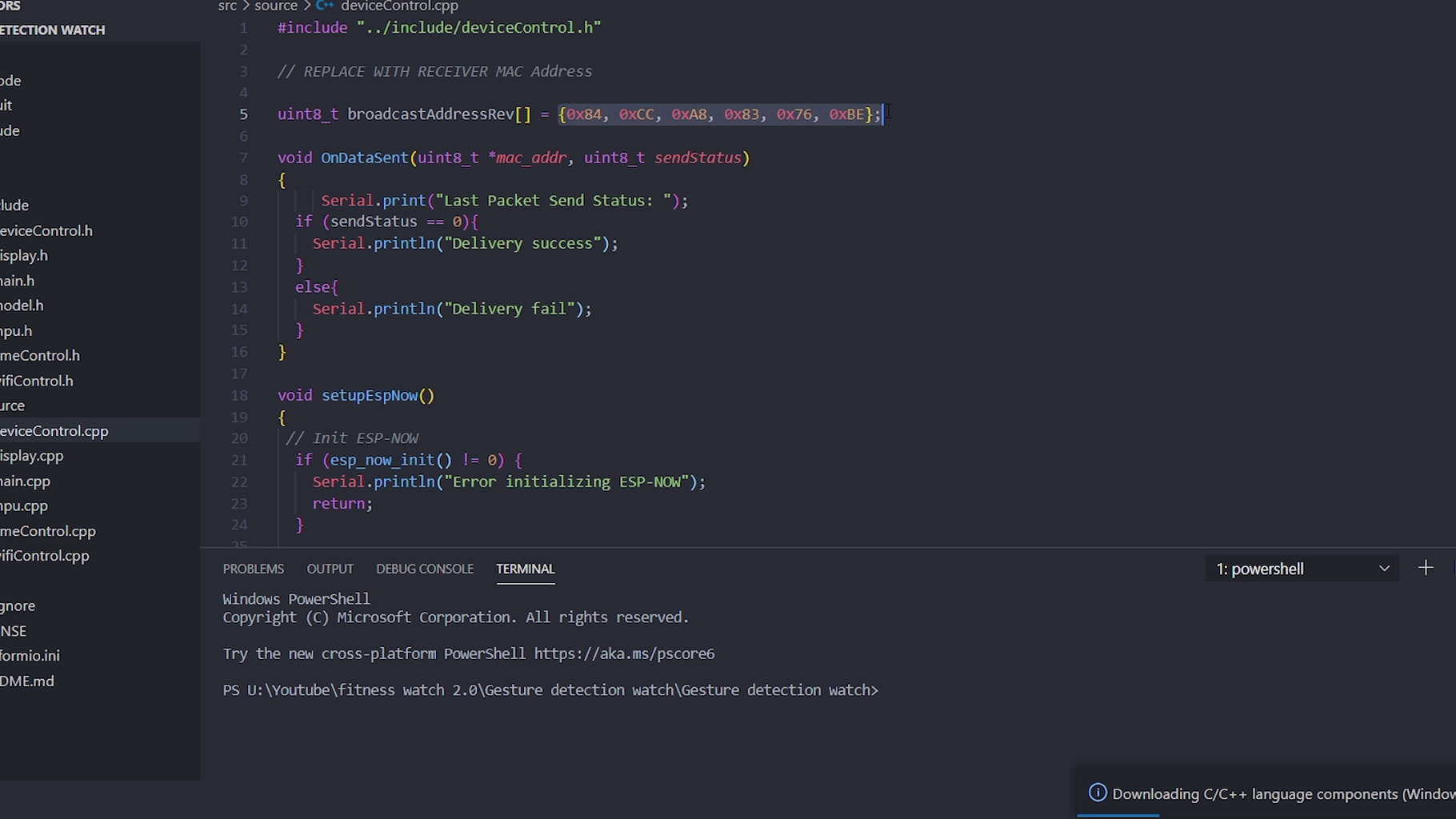
} struct_message;Unlike the slave, for the controller we need one additional info, to send the data i.e the MAC address. Replace the MAC address with your slave device mac address, and that should be it!
uint8_t receiverAddress[]= {0x84, 0xCC, 0xA8, 0x83, 0x76, 0xBE}; // Replace with your MAC addressThen compile and upload the code. Now to test, fire up the serial monitor in your Arduino IDE and start sending the character a, b, c, d and the corresponding LED’s should toggle HIGH and LOW!
If you are into this project for this long, probably you should consider subscribing to my Youtube channel and the instructable page and also Voting to this project as well as check out my other projects/videos, which will definitely keep me encouraged in making more interesting projects like these!
Attachments
Step 8: The Smart Extension Box


Since we are familiar with the ESP NOW protocol we can now work on the hardware to control the home appliance. There is a very high chance that you would have seen a similar project explaining how to do home automation using NodeMCU. But sometimes it’s not practically usable or it just fiddley to use.
But in this instructable we'll see how to make a very good looking and highly useable device, where you can directly connect your high voltage appliance (up to 5A) and use them, and if you’re done with the device you can simply switch the device like you always do with regular sockets!
Step 9: Extension Box Hardware


I bought of these extension box casing for this project, I'm not sure if it’s available online. But if I find something similar I will make sure to put the link in the description but I was luckily enough to get these in an offline store for around 1$ - 1.5$. If you couldn’t find this you can use any existing extension box and modify it.
I wasn't sure whether a four 5V relay will fit in within the case, so I bought these case 2 variants, where one has individual switches for each socket and the other one has one common switch for all the sockets. Then after trial and error I found that, the one without many switches has more space inside where I can place the relay. These relays will later be controlled by ESP8266 to control the AC supply to the socket.
I just tried to visualize how we can place the components inside the case, then roughly mark the dimensions on a perf board for the circuit. The case which I'm using have an additional space for a fuse (it's highly recommended to use the fuse) I'm going to get rid of this so I can place the circuit and for the fuse I will drill an additional hole where I can add a new 5A fuse through a external fuse holder.
Step 10: Extension Box Circuit


To power the circuit I chose a Hi-link module which has output of 5v, 5W, the reason to use this Hi-link instead of custom built rectifier circuit is because Hi-link has a very wide range of input voltage from 100V - 240V AC and also comes with features like low noise output, short circuit protection, overcurrent protection and very high reliability.
Then we’ll use a multiple relay to turn on each socket, and esp12E for the microcontroller and finally terminal blocks for connecting AC supplies. Since the esp12E works with 3.3V, we’ll be using this ASM1117 regulator to step down the 5v from Hi-link to 3.3V. Along with that a few components like diodes and resistors are used, and that should be pretty much components required for this circuit. For more detailed connection, you can download the circuit diagram from the link in the description.
Once the slave device is done and it can control one socket, but we have 4 sockets in the casing, So we’ll build 3 modular custom built relay circuits to control these sockets.
This circuit should be pretty much simple and basic, All you need is a perf board, Relay, terminal block, RMC connector, resistor, diode and a transistor. Here the transistor will act as a switch which will be controlled by our esp8266 and this will turn on the relay and switch on the power to the socket.
At this point we’ll just replicate this 2 more times and it should be done for the hardware part and see if you can place these circuit inside the case and see if everything sits in place perfectly.
Step 11: Need to Develop This Project Into a PCB?

Getting a electronics project into production would be nightmare. To ease you into the production world we have developed a platform (PCB CUPID) for PCB enthusiasts and hobbyists to ask and answer questions related to PCB design, fabrication, and assembly.
In addition to the Q&A feature, this website also has a wealth of blog posts and useful resources to help you learn about developing and manufacturing printed circuit boards. Whether you're a beginner looking for a crash course on PCB basics, or an experienced designer looking for tips and tricks, you'll find something of value on the site
So head on over and check it out, and don't forget to participate in the Q&A community to get help and share your own knowledge. Thanks!
Step 12: Extension Box Programming


Make sure to test if the circuit is working as expected, for that just switch the jumper to programming mode in the circuit and upload the code Testing_Relay.ino to esp12E through a FTDI module. Once the programming is done, put the jumper back to it's old position.
This code will test the relays and check if all the relays are working properly. Since we don't have any visual feed back for relay switching you can place your index finger on the relay to feel the relay switching action. If everything is working good, we can upload the same code (Esp_now_reciever.ino) that we used while learning about ESP NOW. Here Instead of the LEDs, the esp12E will trigger the relay through the transistor. Which will in turn, turn ON and OFF the power to the respective sockets.
Step 13: Extension Box Wiring


Caution : From this step you need to be very careful because the wiring involves high voltage and mains power(110V / 240V) so any mistake or short circuit could potentially be dangerous. So proceed with caution.
Now, we can do the wiring inside the case. First start with connecting the live, neutral and earthing wires to the sockets pins. You can see in the image the neutral wires are commonly connected to the socket as well the earthing/ground wire. Live wire is connected through the relay, so we can control the power to the socket. You can check the circuit diagram for better understanding on how to do wiring. Also while wiring be sure you isolate everything properly as well as use heat shrink, or insulation tape to prevent the circuit from having short circuits internally. Once everything is placed and wired in, use a bit of hot glue just to make sure everything is in place properly. This completes the hardware build for the extension box!
Attachments

Step 14: Extension Box Testing


To trigger the relay in the extension box we need a controller device to send the data. We can use the same controller device that we used earlier and connect it to a pc and fire up the serial monitor. Now as you send the characters in the serial monitor the relays should turn on and give AC supply to any appliance connected to it. Here you can see my mobile adapter is connected and also can see the current drawn by my phone when it’s charging. And similarly all the sockets should provide an AC voltage to drive the AC device.
Step 15: Gesture Control of the Extension Box


Since the extension box is working excellent, all we have to do is just change some code in our watch, so we can turn on and turn off the home appliance with a hand gesture! Check my previous instructable on how to do that in more detail.
Go to the gesture detection watch folder and open it with VSCode. Then replace the Mac address with your reciever MAC address and then upload the code to your watch as we did in the previous videos. That’s it!
Now, you test the watch and the extension box! They both should work together, when you do different action with the watch, the corresponding sockets will turn on and turn off.
Step 16: Final Thoughts!

After 3 long instructable we are finally done! The time spent on this would be definitely worth it, even if you don’t plan on using all these features together you can build them as an independent project. Like Building a watch, implementing ML on microcontrollers and making a home automation system.
Please note the final device looks and works well, but to cramp in the relays inside the case I have to sacrifices few components like optocouplers, led indicators etc.
Maybe in the next instructable I will implement those and along with that we'll see how to use ESP home with home assistant. So, if you’re interested in it, let me know in the comment section.
Until the next instructable you can read or watch my other projects from these links Youtube / Instructable. See you next time with a new and exciting topic.

Participated in the
Automation Contest


