

Introduction: Smiling Arduino


Hi! Do you like electronics? Because I love it. Especially I love anything which displays results, like monitor. And today I'll show you how to make that Arduino will smile(and do some other stuffs :). So this instructable is about fun with Arduino and led matrix. At the end of this instructable I'll show you how to control led matrix by computer.
If you wanna to see human in Arduino stay with me!
Step 1: What You Will Need

You need:
Arduino(I use Nano, but you can use any other),
red led matrix,
MAX7219,
potentiometer,
10k ohms resistor,
8 220 ohms resistors,
2 breadboards
and a lot of wires.
Step 2: What Is Led Matrix and How It Works

So led matrix is nothing more than few leds connected together. There are two types of led matrices: common-row anode and common-row cathode.
Common-row anode:
anodes(+) of diodes are connected together in rows(look at image), so each diode's anode is connected to diode's anode from left and right. cathodes(-) of diodes are connected together in columns, each diode's cathodes is conencted to diode's cathode from top and bottom.
Common-row cathode:
vice versa to common-row anode. Cathodes are connected in rows, and anodes are connected in columns. For just one color matrices is doesn't matter but for bi-color or rgb it matters a lot.
On image is 8x8 led(dot) matrix but there are bigger, and it doesn't have to be square but in this instructable I'll use 8x8 red common-anode led matrix.
OK, but how do I know which led is which?
If you want to turn on led you have to know in which row it is and in which column. Letters and numbers are like coordinates. Letters(from A to H) are x coordinates and numbers(from 0 to 7) are y coordinates.
Step 3: Connecting Your Matrix


Almost every matrix has different arrangement of pins. So you have to look into datasheet or do some experiments.
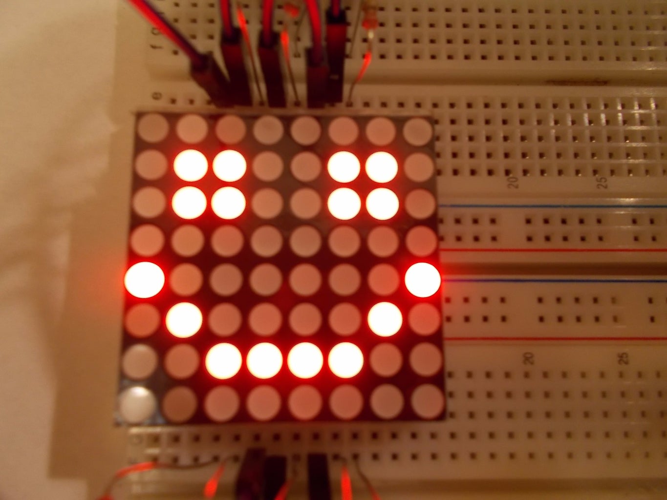
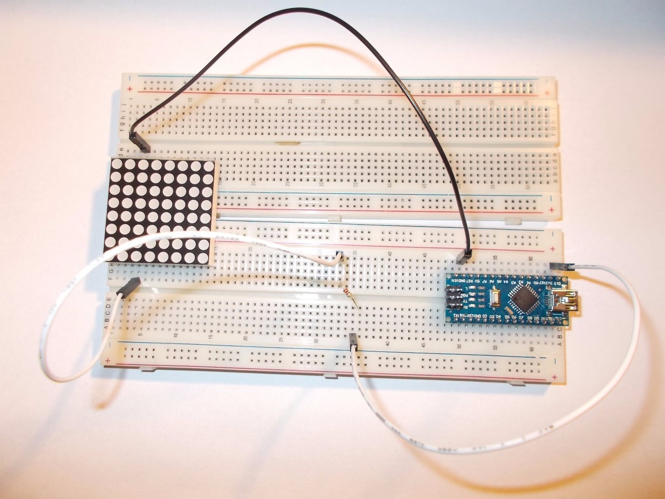
Plug your matrix into two breadboards that text(on one side) are in front of you(image 1), so if you look at it from top this text should be on bottom. Next connect top left pin on matrix to GND and bottom left pin on matrix to 13 I/O pin on Arduino through 220 ohms resistor(image 2).
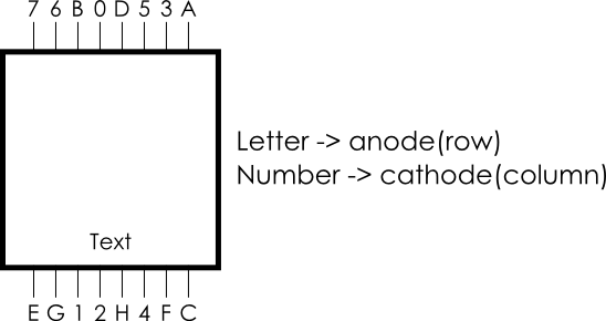
Draw diagram of your led matrix(image 3). Now download test code and send it to Arduino. It's like blink but there's no turn off. I've got luck, one led turn on for first time. If your not just switch wires. Now count from top to bottom at which row the led turned on. Under(or above) pin to which you've connected +(pin 13) write proper letter. Count from left to right at which column the led turned on. Above(or under) pin to which you've connected -(GND) write proper number. Now move + wire right and check if another led turned on. If it does save proper value for pin(only row because column stays the same). If it doesn't move + wire left to previous position and connect next to it - wire. If you've done all bottom pins go to top pins. After you found what each pin does your schemat should looks like on image 5(there might be some difference in numeration).

Step 4: Wiring


We could connect matrix to just Arduino, without MAX but it's easier to use it. First - it's easier to program, second - you control it with just 3 pins. Look at first image. On first image is MAX7219 diagram. Now connect pins from matrix to MAX - A on your diagram to A on MAX diagram. Letters connect through resistor 220 ohms, numbers directly to MAX. Now ISET(on MAX) connect to V+(on MAX) through 10k ohms resistor, V+ to +5V, DIN pin on MAX to 8 I/O pin on Arduino, LOAD pin on MAX to 10 I/O pin on Arduino and CLK pin on MAX to 9 I/O pin on Arduino. DOUT is not connected. It would be used if we will connect more MAXs. I've made connection schemat but it may be different for your matrix.
Now download and send test_max program. You should see dot moving from left top corner to right down corner(look at video). If it's moving as I described you can download second code named blink_face. You'll see smiling face which blinks. It's bonus from me :). Read carefully comments in this code. Now let's move to our title smiling face.
Attachments
Step 5: True Magic

OK, let's make Arduino smile. To do this you'll have to add potentiometer to our circuit. If you'll move potentiometer Arduino will smile more or less. So middle pin connect to A0 on Arduino, and others to GND and +5V - order doesn't matter. Now code - download smile and send it to Arduino. Now if you move potentiometer it smiles more or less. Good job! But that's not the end! Last thing we wanna do is to control matrix by computer.
To do this we need processing(which you can download here). If you downloaded it open it. I created my program in Python(which is really great programming language :) so you need to download Python mode. Click on Java in white rectangle and click add mode. Click on Python and click Install. If you downloaded Python mode we can go to code. First download show_anything. In this file is .ino file which you should send to Arduino. But there is also folder named draw_anything. Inside this folder is file named draw_anythin.pyde. Open it by Processing(probably you have Processing 3 and I made it with Processing 2 but there shouldn't be any problems with it. If they are please let me know). There you should see my code. Just follow instructions and you'll be able to control led matrix by computer. Soon I'll add option to making animation from computer.
That's the end! Thanks for your time! Hope you enjoyed it. See you soon!
Attachments

Participated in the
Arduino All The Things! Contest

Participated in the
Full Spectrum Laser Contest 2016

Participated in the
Rainy Day Challenge


