

Introduction: Solar Energy Flowing Cables – Glowing Solar Power Flow Effect Powered Directly Off of Solar Panels. No Charge Controller USB Voltage Glowing Flowing.


Solar power is interesting but it would be awesome if you could see the energy flowing through the cables from the solar. This project is just that powered directly off the solar panels with no charge controller. This project ties into my Steampunk Solar Panel Combiner Box Project and is connected to two different solar panels which gives it a pretty cool effect. The cable for each panel is independently controlled so if only one solar panel is in the sun only one does the solar energy flow effect.
If you would like to support me in making these projects you can do so here.
Supplies
Here is a complete list of Supplies & Tools you will need. They are not all the same supplies I used but should be similar or better replacements.
Disclosure: The links below are affiliate links. This means that, at zero cost to you, I may earn an affiliate commission if you click through the link and finalize a purchase. I am a participant in the Amazon Services LLC Associates Program, an affiliate advertising program designed to provide a means for sites to earn advertising fees by advertising and linking to Amazon.com.
Supplies
- USB LED Light Strip RGB – (Finding one of these that was inexpensive, USB, had the effect I wanted, and memory so it auto restarts the effect took quite some time but these turned out great!)
- 8-35V to 5V 3A Voltage Regulator – (With this the LED light strip above can be ran directly off the solar panel itself. Be sure you get one that supports the max voltage of your panels, for me this one was more then enough.)
- Screw Mount USB Power Cables 2 Pack – (This would be a better connector for the Solar Combiner Box so you could use a standard USB Extension Cable.)
- USB Extension Cable – (If you do the above instead then a standard USB Extension Cable can be used.)
- USB Breakout Board Adapter – (I used these because I already had them, above would be an easier option but an alternative to this also below.)
- USB Female Power Cable Ends – (If you don’t want to solder or use the USB Extension Cable this would be a good option.)
- Male & Female Connector Wires 2 Pin – (I used these because I already had them, a better option is above of Screw Mount USB Power Cables.)
- 22 Gauge Cables – (I used old speaker cables I had lying around but this or similar will work fine.
- Spade Crimp Connectors Kit – (Used to connect Voltage Regulator to the solar panels inside the solar combiner box.)
- O-Ring Crimp Terminal Connectors Kit – (It comes in 3 sizes and 3 different ring sizes which makes it easy to find a close fit. Used on the analog meters backs.)
- Straight Splice Crimp Connectors – (If you want to avoid soldering these are an easy way to connect 2 cables together. This would be best if you are making your own cable using the USB Female Power Cable Ends instead of the USB Breakout Board Adapter. I show these used in a later step.)
- Wire Ties Assortment – (Used to attach the LED Light Strip and USB cable to the solar cable.)
- Solder Wire Lead Free Rosin Core Flux – (This is a lead free all in one soldering wire that has a rosin core flux so you don’t have to apply it separately. This is similar to what I used. If you don’t want to solder at all do the Screw Mount USB Cables and USB Extension Cable Approach or Instead of USB Breakout Boards get the USB Female Power Cable Ends instead.)
Tools
- Ryobi Soldering Station – (I used a Ryobi one but a variable heat soldering station like some of these would work as well. If you don’t want to solder at all do the Screw Mount USB Cables and USB Extension Cable Approach or Instead of USB Breakout Boards get the USB Female Power Cable Ends instead.)
- Ryobi Glue Gun – (I used a Ryobi one but any glue gun like these would work. Depending on your wall situation wire staples might work better.)
- Wire Staples – (If you are doing this on a drywall or wood wall wire staples will work better then hot glue. Using these you won’t need the glue gun.)
- Quick Wire Stripper – (Not required but saves time when stripping wires.)
- Wire Stripper & Crimper – (This is required to do the crimping on this project and can strip the wires as well.)
- Angled Wire Cutter Set – (Any wire cutter will work, and the above tool also has a wire cutter.)
- Auto-Ranging Multimeter - (This is a similar style to the one I am using, any multimeter you have should work. If you don't have one this is not required it is just used for testing.)
Step 1: Testing 5v Voltage Regulator


First we start by testing the 5v USB Voltage Regulator directly off of the solar panel which is about 25v in full sunlight. These 5v Voltage Regulators advertise anything from 8v to 35v will work.
Step 2: Testing 5v Voltage Regulator With LED Strip


This is the proof of concept test to be sure I can run the USB LED light strips off of the solar panels using the 5v voltage regulator. These strips call for about 2amps so this has more then enough and it worked as expected in this test. I also needed to test the LED strip for the effect I wanted and a memory ability when power to the LED strip is lost so it would do the same effect next time power is restored and it did both.
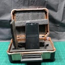
Step 3: Feed Connector Into Solar Combiner Box


This project ties into my prior project called Steampunk Solar Panel Combiner Box while not required to do this project, it made everything look cleaner then just having it hanging off the wires. I used these 2 pin connectors I already had lying around, but using a mountable USB port would have worked better. I fed the connector through the empty screw holes in the back so it would be behind the solar panels SAE connector.
Step 4: Strip & Fold the Wires


Strip and fold over the wire from the 2 pin connectors if you are using ones like I did. They need to be folded over for the spade connectors to work as the wire is too small for the spade connector without being folded over at least once.
Step 5: Add & Crimp Spade Connectors


Now add and crimp on the spade connectors to the 2 pin connector. I used a male spade connector for all of them so they wouldn’t be able to be connected to each other accidentally.
Step 6: Add & Crimp Spade Connector Onto 5v Voltage Regulator


Then strip the cables and add a spade connector female onto the output yellow and black cables of the 5v voltage regulator. On the input red and black cables crimp O-Ring connectors. These will be connected to the back of the analog voltage meters. If you have two solar panels like I do then do this again so you have 2.
Step 7: Plug in 5v Voltage Regulator Output


Next plug in the output from the 5v voltage regulator (yellow and black) wires into the 2 pin female connector that goes out behind the SAE connectors in the solar combiner box.
Step 8: Connect 5v Voltage Regulator Input to Analog Meter


Connect the 5v voltage regulator input (red & black) wires to the back of the solar combiner analog meters and screw them into place. Be sure the positive is on the positive and negative on the negative. I found fanning out the O-Ring connectors like the picture made them all fit and look better.
Step 9: Testing With Solar Panel Connected


With that all plugged in and ready to go I tested the solar panel with the multimeter.
Step 10: Testing 5v Voltage Regulator With Solar Panel


Now I tested the 5v voltage regulator by plugging in a male 2 pin connector into the female 2 pin connector that is behind the SAE cable. Everything is working so its time to continue.
Step 11: Positioning the 5v Voltage Regulators


I tried a few different locations and decided on these ones for the voltage regulators to go that would be mostly out of the way and work with the amount of wire available.
Step 12: Glue Down 5v Voltage Regulators


Since these are going to be attached to the back side of the front panel I used hot glue instead of screws as I don’t want screws going through the plastic and showing up on the front of the solar combiner box.
Step 13: Testing Both Solar Panels With Both 5v Voltage Regulators


With both sides done and connected it is time to do one more test before continuing, they work so now we get into the rest of the project where the actual cool stuff happens!
Step 14: Solar Panel Cables


This is where the solar panel cables come in so I pulled them over to the next space between the 2x4s and attached them at the top with wire staples.
Step 15: Cut Cables for USB


I used some old speaker cable I had lying around in order to make my 2 pin connector to USB cable. Cut them to the length of your solar panel cables and then split the cable ends apart and strip them.
Step 16: Solder & Trim USB Breakout Cable End


If you want to do this project exactly like I did then solder the cable into the breakout board. If using clear speaker cable like mine the end that has the white stripe I connected to the positive ends. On my breakout board the positive is called VBUS and the negative connects to GND. The D+ and D- are unused as this is just a USB power cable we are making. If you don’t want to solder at all do the Screw Mount USB Cables and USB Extension Cable Approach or Instead of USB Breakout Boards get the USB Female Power Cable Ends instead and skip this step and the next.
Step 17: Hot Glue & Reinforce USB Breakout


Hot glue the soldered cable ends of the breakout board to protect it and add some extra hot glue around the USB connector on top and bottom as these tend to be the weak parts of USB breakout boards.
Step 18: Crimp Coupler From Cable to Connector


You could also solder these and put on heat shrink tubing but instead I went for crimp connectors to attach the 2 pin male connector to the USB power cable. If you skipped the soldering and got the USB Female Power Cable Ends instead this is also how you will attach those two cables together as well. If you did the Screw Mount USB Cables and USB Extension Cable approach you can also skip this step.
Step 19: Twist LED Strip Around Solar Cable & USB Cable


Now we get into the heart of this project. Start at the SAE connector end and fold the end of the LED light strip over just a little below the LED itself and then wire tie it around the SAE connector. From there start twisting it up around the cable being sure the LED is always on the front of the cable. Also be sure to put the USB cable behind the solar power cable before you do this so it is held in place by it. On the first solar cable I wire tied every single time I got to a soldering point of the LED strip, on the second cable however I did every 2 and that worked smoother. It ended up with about a 1 inch or so gap between LEDs which works just fine. You could try the adhesive back but that would actually make this project harder as the LEDs do not like to twist around to directly in front some times and the adhesive will make it harder to position and might fall off. I found wire ties to be the easiest way for me and it has the ability to be removed in case a repair is needed or you have to change out a cable in the future. If your LED strip didn’t have a roughly 2-3 inch gap between LEDs you could probably just use the adhesive and run it straight up the front of the solar panel cables. I couldn’t find one at a price I was willing to pay or in USB 5v voltage so I just went for twisting it around the cable. I have a few more pictures in a later step with the second cable.
Step 20: Plug LED Strip Into USB Cable


Once you get to the top of the solar panel cable plug in the LED Strip into the USB port. I also wire tied the controller so it would be upright and face forward so it could be pressed easily in case I need to access it without the remote. I attached the remote near the top of these as well so I always know where it is with a twist tie on an unrelated wire I have going across the top of the wall.
Step 21: Testing LED Strip on Solar


After getting it all twisted and wire tied to the cable its a good idea to test it all and make sure it is glowing properly.
Step 22: Twist LED Strip Around Solar Cable & USB for Second Solar Panel


My setup has 2 solar panels connected into the solar combiner box so now to repeat the whole process onto the second cable. On this one I went every 2 soldering points with a wire tie and it went faster and smoother. Just twist it around 3 or 4 times until two LEDs are after the last wire tie and then attach one between the second soldering point of the LED strip which is the copper colored part. Do this all the way to the top and then plug in the USB and wire tie it and the controller to the top just like the first.
Step 23: Quick Test of Both Cables on Solar


Now one final quick test before attaching the cables to the wall to be sure it is all working. Which it is so time to continue!
Step 24: Attach Solar Cables With LED Strips to Wall


In my case I have wall insulation that is styrofoam with a heat reflector between the 2x4 slats of the walls. The best thing I could get to work was to poke the wire tie into the styrofoam and hot glue it all in place. I used a lower heat hot glue gun as styrofoam melts really easy. If you don’t have a low heat use your high heat and then unplug it for a few minutes till it starts to cool off and then use it. If you have normal drywall or wood wall you can use wire staples instead. I had to attach the cables to the wall because my cables would keep twisting a bit which made the LEDs not all face forward. That and it also looks better in a straight line instead of all curved with the natural curve of the cable. If you don’t want to attach it directly to a wall you could get some wooden dowels, metal rods, plastic tubing or some other type of rigid pole to attach them to.
Step 25: Plug Into Solar Combiner Box


With the cable attached to the wall its time to plug it in to the Solar Combiner Box.
Step 26: Attach Second Cable to Wall & Plug In


Attach the second cable to your wall similar to the first and plug it into the solar combiner box. For my second cable which was longer then the first I started on the bottom and worked my way up the wall unlike the first cable which I attached to the wall from the top down.
Step 27: Turn Both on at Same Time


Now is the moment of truth, flip both switches on at the same time and see if it all works.
Step 28: Energy Flow Glowing Effect


Here is the energy flowing glowing effect with pictures. There are videos in the last steps as well so you can see it in action. It slowly runs from the top of the wall where the solar panels come in down to the Solar Combiner Box where it goes out to the charge controllers and battery. The effect is a blue flowing effect kind of like rain. It is exactly the effect and color I was looking for.
Step 29: Energy Flow Glowing Effect Lights On


So you can also see the cables I turned the lights back on and did the same effect. I also recorded a video with the lights partially on.
Step 30: Finished Cable Lights On


This shows the entire length of the cable that is visible from top to bottom with the glowing effect still running. As you can see one of my cables was longer then the other so I had to curve it at the very top and then straighten it out. I had originally made both cables the same length when I hammered in the wire staples on top but it was not tight enough and the cable slid as I applied the LED strips which I didn’t notice till I had finished unfortunately.
Step 31: Finished Project, Solar Energy Flow Cables Completed


Here is the finished Solar Energy Flow Cable Project. Complete with a video and lots of pictures! This is exactly the effect I was hoping it would have where it not only looks like the energy is flowing down the wire from the solar panel it is directly powered off the solar panel so it actually is flowing from the panel. This is much more pleasing to look at then just the generic solar panel cables were!
Step 32: Other Ideas, Upgrades, and Effects
Here are some videos of the other glowing effects of these LED light strips and the effect I like the most at different speeds. I changed the effects and speed every couple of seconds and left it longer on the better looking effects.
Here are some upgrade ideas:
- Adding a light diffuser so the whole cable itself looks like it is glowing would look even better. I will add this upgrade in the near future. One option is with silicone flexible LED strip channels like this but they are oddly expensive for lot a lot of feet. I am going to try a few other cheaper materials and see if they work well enough.
- Addressable LED Light Strip controlled by a Raspberry PI, Arduino, or similar control board. These are nice because the LEDs are only maybe a quarter to half an inch from each other so they could be ran straight up the cable. However to get the effect I wanted I would have to do the Raspberry Pi or Arduino approach which will cost more and take more time to do.
If you would like to support me in making these projects you can do so here.
Do you have any more suggestions? I will add good ones to this list and if there is enough demand I will possibly do some of these ideas in the future.

Participated in the
Make it Glow Contest


