

Introduction: Computer in a Briefcase Hard Drive Tools Recovery & Wiping – Highly Portable HDD Managing SATA, IDE, & Flash Memory Cards. Tron Style Glowing Outside!


Have you ever needed portable computer for hard drive recovery and nuking tools that does not take up too much room and can be easily transported with SATA, IDE, & Memory Cards Support? Or maybe you just need a highly portable computer that is also quite compact when not in use and looks great. If so this project is for you, so lets dive right in and get started!
If you would like to support me in making these projects you can do so here.
Supplies


Here is a complete list of Supplies & Tools you will need. They are not all the same supplies I used but should be similar or better replacements.
Disclosure: The links below are affiliate links. This means that, at zero cost to you, I may earn an affiliate commission if you click through the link and finalize a purchase. I am a participant in the Amazon Services LLC Associates Program, an affiliate advertising program designed to provide a means for sites to earn advertising fees by advertising and linking to Amazon.com.
Supplies
- Older Working Computer – (I will use one I already have lying around but if you don’t have that here are some options for micro computers that would fit in even more case options.)
- Some Kind of Briefcase or Case – (I used a case for a small camping propane stove but a brief case would work quite well for this project. You would just need to remove the inner organizers and cloth. Be sure to find one with dimensions that can fit the computer you have and a power supply in it.)
- SFX Power Supply – (The case I have was not large enough for a full ATX so I had to use a SFX power supply which I got lucky and is what was in the old computer I used for this project. Another small power supply option is below.)
- Mini ITX Power Supply– (I used the SFX sized power supplies but you can also use a Mini ITX which tend to be longer and flat.)
- Samsung 64GB Flash Drive – (I used one I had lying around but I will upgrade to this at some point so I can leave it plugged in at all times and fit more ISOs of recovery tools.)
- Internal USB Card Reader w/ USB Port – (I had one lying around but this is very similar to what I used. It plugs into the internal USB header of the motherboard and give you a USB port and card reader for various flash media cards.)
- Internal USB 2.0 Ports – (If you don’t care about the card readers at all you could use something like this to give you 2 internal USB 2.0 Ports)
- Mini USB Keyboard & Touchpad – (Not required but is handy if you want this to be more all in one only needing a monitor to use.)
- Ice Blue 12v LED Glow Strip COB – (This is the one I used and it comes with a diffuser and a lot more LEDs then most LED Strips. I chose this style for the light diffuser which looks much better then just exposed LED strips.)
- Upgrade: Color Changing LED Glow Strip COB – (If you want to be able to change the colors this would be an upgraded version.)
- Update: Cheap LED Controller – (Controls the brightness and gives you a few effects.)
- Solid Core Wire Two Color – (Similar to what I used but in Red and Black.)
- Solid Core Wire Set (6 colors) – (If you want even more variety this kit comes with 6 wire colors in an easy to use box.)
- Heat Shrink Tubing Set – (Cheaper to buy a various size set then just one size and this gives you a lot to work with for future projects as well.)
- Silicone Tape – (Not required if you have multiple heat shrink tubing sizes but this works much better then electrical tape and sticks to itself which is nice if you forgot to put the heat shrink tubing before soldering or accidentally had it shrink due to the soldering iron heat.)
- Solder Wire Lead Free Rosin Core Flux – (This is a lead free all in one soldering wire that has a rosin core flux so you don’t have to apply it separately. This is similar to what I used.)
- Male & Female Connector Wires 2 Pin – (Similar to what I used to connect the ATX power supply to the LED glow strip. You could also use this Molex to Barrel Plug Adapter which is easier.)
- Wire Ties Assortment – (Used to help with cable management of the power supply and card reader.)
- Velcro Wire Ties – (Used for holding the SATA and Ribbon data cables to the power cables and being easily removable when using it.)
Tools
- Ryobi Soldering Station – (I used a Ryobi one but a variable heat soldering station like some of these would work as well.)
- Ryobi Glue Gun – (I used a Ryobi one but any glue gun like these would work.)
- Ryobi Cordless Drill – (I used a Ryobi but any drill would work like these.)
- Ryobi Rotary Tool – (I used a Ryobi but any rotary tool like these would work.)
- Anti-Static Wristband Kit – (While not required I prefer having this so I don’t accidentally fry any computer parts from static.)
- Quick Wire Stripper – (Not required but saves time when stripping wires.)
- Wire Stripper & Crimper – (This is needed to strip the wires if you don't have a quick wire stripper.)
- Angled Wire Cutter Set – (Any wire cutter will work, and the above tool also has a wire cutter.)
- Tin Snips – (Can cut plastic with ease, though it does sometimes cause it to crack.)
- Auto-Ranging Multimeter - (This is a similar style to the one I am using, any multimeter you have should work. If you don't have one this is not required it is just used for testing.)
- Drill Bit Set – (You will need some drill bits in order to drill holes in the case.)
- Small Socket Set – (Used to screw in the motherboard standoffs, you could probably just use plyers but it would take longer. I just used the extension arm and the socket that fit the standoffs which was 3/16ths.)
- Optional: Brother Label Maker – (Similar to what I used, but is a newer version, to make the labels.)
- Almost All In One Kit – (I don’t know if the quality of this is good but it does have pretty much everything you need as far as tools and basic supplies all in one for pretty cheap. It would probably be a good starter kit until you could afford to get better tools and supplies.)
Step 1: Test Motherboard Fit in Case


Now the case I have is not technically a briefcase but rather a case for an old butane single burner stove but the steps would be the same for the most part for your brief case. I also took pictures after I had cut off the corner seen in step 2 so just pretend its still there in these pictures. I put some motherboard stand offs and screwed them into the motherboard so it would be elevated off the plastic a bit which will help with airflow and heat later on.
Step 2: Cut Off Corner of Motherboard (If Needed)


The case I had couldn’t fit the Motherboard and Power Supply without me pushing it way into the corner requiring me to cut off a corner of the motherboard. Luckily for me the motherboard didn’t have any critical wiring or components on this side. If yours has any of the small wiring or components do not do this step or you will break the motherboards electrical connections.
Step 3: Mark VGA Monitor Port


Now we will start with the port that sticks out the most and is most required which is the VGA monitor port. If you use a newer computer it will probably be DVI, HDMI or even Display Port. The process is the same either way just mark out the hole size plus a bit extra for the cable to fit.
Step 4: Cut Out VGA Hole


I used a combination of a Ryobi Rotary Tool, Tin Snips, and Angled Wire Cutters to cut out a hole, expand its size and clean up the edges.
Step 5: Mark & Cut USB, Ethernet, & Extending Ports


The only ones I needed here were the USB & Ethernet ports, however the audio ports also extended too far to just leave so I cut them out as well. The ports you have to cut out on yours that extend too far will be different so cut the ones you need to. If your brief case is taller you could just cut a large rectangle that fits the back panel of the motherboard and that would be a lot cleaner. I tested it against this case but unfortunately for me the case was not tall enough and would have greatly ruined the cases durability with such a massive hole cut out of the bottom and lid of this case.
Step 6: Remove Standoffs & Mark Motherboard Screw Holes Onto Case


Now remove the stand offs from step one and then mark the holes for the next steps.
Step 7: Size Drill Bit to Stand Offs & Drill Holes


I used a motherboard screw since the threading on it is the same as the stand offs. I just put it in the smallest hole it fits snugly and went with that bit. If you are using standard motherboard stand offs like I did it was a 7/64ths drill bit. Then drill all the holes you marked out.
Step 8: Screw in Standoffs & Straighten Them (If Needed)


Since the holes are snug even through there is no threading in the hole you can still screw them in and have the standoffs make the threading groves for you in the plastic. The case I used is not perfectly flat on bottom so after screwing in the stand offs I had to straighten them out until they were straight enough for a screw to fit in. I also missed one hole near the cut corner and redrilled it, but it turns out that corner is just high enough I would need an extra long screw so I just left it out. All holes having a screw except one is more then enough to hold it all snugly in place.
Step 9: Screw Motherboard Into Standoffs


Now if you marked everything properly and straightened them enough screw in the motherboard into all the stand offs you can. Before putting screws in make sure the holes line up with the stand offs. I had at least 2 that required additional straightening with pliers. Then once its all screwed in make sure it holds in place when upside down.
Step 10: Hot Glue Protruding Standoffs


There are a few reasons for this step: first it holds the standoffs into the case even better, second it stops it from scratching up the surfaces you set it on, and third it also provides some non slipping capabilities so the case shouldn’t move around on a smooth desk as much.
Step 11: Test Fit Power Supply & Mark It


I happened to have this mini style power supply that came out of the old compaq case this computer came out of which is a SFX form factor. It doesn’t have to be a mini one if your case is big enough to support a full sized ATX power supply would be easier. This one is very low being only a 180w power supply but for just 2 SATA, 1 IDE, and/or Flash Memory Cards it is enough.
Step 12: Cut Out Power Supply Plug


I used tin snips to try and save time along with wire cutters but it was not a very clean cut and shattered parts of the plastic I then cut off with the wire cutters. The rotary tool would have been much cleaner for this step.
Step 13: Mark & Drill Multiple Vent Holes for PSU


Since the main air intake is right against the side of the case I needed to drill lots of vent holes to be sure it would get enough airflow so the power supply doesn’t overheat.
Step 14: Drill Screw Holes to Attach PSU


Drill screw holes that can attach to the power supply. These are the 4 holes that normally attach it to the computer case. I drilled 3 holes to put screws and then did the next step instead of a fourth screw. Drill very slowly so you don’t accidentally drill out the threading of the power supply screw holes which would cause metal shards to enter the power supply and possibly short it out. Don’t worry if you miss the first time it just gives it another hole for ventilation.
Step 15: Add Fan Screw to Increase Airflow


Even with the holes I drilled I still wanted it to have more airflow so I took a computer case fan screw and put that in so it would put a gap between the plastic with the drilled vent holes and the air intake of the power supply. I did not put this screw into any hole in the power supply it just rests against the outside of it and is purely to space the plastic from the power supply a bit.
Step 16: Glue Down Power Supply Also


The screws keep it in place but since the case isn’t flat it still isn’t stuck down enough. So on top of the screws that make sure it stays in place I also glued down the power supply to be sure it wouldn’t pop up at the slight angle it was at before the glue.
Step 17: Plug in & Glue Down Power Cables


While plugging in the main motherboard power cables and CPU power cable I roughed up the case so glue would stick and glued down the main motherboard power cable so it would be more compact and not move around. You could also drill another 2 holes and run a wire tie through it but I went for glue.
Step 18: Attach SATA Power Adapter (If Needed)


The power supply I used didn’t have any SATA power cables so I attached a Molex to two SATA adapter. If yours already has them you can skip this step.
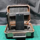
Step 19: Disassemble USB & Card Reader


I needed a USB port inside to run the flash drive with the recovery tools software and happened to have this one from an old computer lying around that also had the most common flash media slots like SD, Micro SD, etc. Since this whole machine is for hard drive recovery & wiping it was the perfect match to allow me to also work on flash media cards also. I couldn’t fit it in the case with the large metal enclosure it was in so I took it apart and found out it was about half the length which was perfect.
Step 20: Glue Card Reader Front Plate Onto Its Circuit Board


Since it will no longer be inside the card readers metal shell glue the plastic card reader front onto the circuit board of the card reader, be careful not to block any of the ports with the glue. The case I was using couldn’t fit and close with the metal case but fits perfectly with the tiny circuit board and front plate inside it.
Step 21: Glue Card Reader Onto Side of Power Supply


I tried a few locations inside the case and the best way I could figure out to hold this in place while also being the least out of the way while having easy to access to it was to glue it to the side of the power supply and the bottom of the case. This also was deep enough I can keep a USB flash drive plugged in when closed, that is when I am using my smaller drive that is not shown in the pictures. However this USB flash drive without a shell is one I had lying around and didn’t need for anything else so it became the permanent drive for this machine even though I do have to unplug it to close the case.
Step 22: Wire Tie & Plug in Card Reader


Since it will be portable and space is limited be sure to do good wire management now so the cables don’t get all tangled or break something later.
Step 23: Wire Tie the SATA & Molex Power Cables


Using a velcro wire tie, organize the cables and tie them down. I put the PATA for IDE drives in one corner where I later attach a Ribbon Cable (Step 25) and the SATA adapter where I also later attach SATA cables (Step 25 also).
Step 24: Plug in & Glue Down Power LED’s & Power Button


I took these power button and LED cables out of a really old computer that was decommissioned long ago and then glued them on the corner of the USB & Flash Media Card Reader and then the power button on the front. This is where the main recovery tools USB port is so it seemed the best place to put the power button and status lights. If you wanted it outside the case something like this would work well and looks nice or you could glue one of these on the inside as well which would also look nice.
Step 25: Wire Tie SATA & IDE Ribbon Cable to Earlier Power Cables


Now attach the SATA data cables to the power cable and a IDE Ribbon Cable to the molex power cable. This way I always have a IDE ribbon cable and SATA cables with it at all times so I don’t have to remember to bring them with it outside of the case.
Step 26: Testing Everything Holds on Sideways


Just to be sure everything was nice and snug I put it up on its side for a few minutes and made sure nothing shifted or fell except for the few not hooked down power cables. I had originally used twist ties to hold the wires but upgraded them to velcro.
Step 27: Closed Case With Labels


I closed up the case and applied some labels printed on a label maker to the side where it used to say the name of the butane stove.
Step 28: Finished Computer Portion of the Project


The computer portion of the project is now completed is now finished and here are some shots of it with the case open.
Step 29: Plugging in Cables & Mini Keyboard


This keyboard is small enough to store inside the case though it will need velcro on the back of the keyboard and top of the case, I didn’t do this in the pictures. Time to get it ready for the next step.
Step 30: Power It On


Time for the first test since starting this project. I tested the motherboard and power supply before doing this project and they were working well so now to make sure it is all still works properly.
Step 31: Plugging in Hard Drive & Powering on Again


Now to do an actual test, I put 4x stand offs on the bottom of the SATA hard drive so it would be elevated off the desk slightly and so the SATA power cable which is angled would fit then powered it back on. I store 4 of these in a tiny bag inside the computer wire tied to the power cables. For this test I used an old 80GB SATA drive.
Step 32: Hard Drive Wiping Software Running


I went with DBAN (Dariks Boot and Nuke v2.3.0) from Ultimate Boot CD (UBCD) v5.3.9 to wipe this hard drive. UBCD comes with lots of different options to choose from for wiping this is just one that I have used prior and had no issues with it. I installed Ventoy and lots of other recovery tools as well so it would be very versatile and fill up the whole USB flash drive. This was to get it ready as quick as I could but in the future I will have it organized into folders with better file names as ventoy auto detects folders. It takes a few hours to wipe with DoD Short 3 passes and this was only an 80GB drive. But that was to be expected.
Step 33: Computer Running & Additional Label


I applied another label to the handle of the case while it was wiping the hard drive and took some more pictures of it running with the label attached.
Step 34: Testing Heat & Adding Heatsinks


Being that the whole case is made of plastic and there are no case fans I wanted to be sure nothing was getting too hot that it would melt anything so I did heat tests with an IR thermometer a few times while it wiped the hard drive. I did find one of the chips on the motherboard was getting well over 125 Degrees Farenheit, which while not too hot was hotter then I wanted, so I took some heatsinks with an adhesive back meant for raspberry pi’s and put 4 of the bigger ones on that chip which lowered its temperature to more like 105 or less which is much better. This case does not have any additional airflow fans like a computer case would so anything too warm needs heatsinks. The CPU and power supply have their own fans so the hottest components will be actively cooled. This computer cannot be run with the case closed it has to be open at all times while running but that is fine since I can also use the lid of the case to hold the hard drives being worked on instead of setting it next to the case like I did in the pictures.
Step 35: Testing Layout for Glowing & Glow LED Strip


Using tape I tested the layout I had in mind and once I liked it I tested the glowing LED strip.
Step 36: Reverse Glow Strip Spool


The LED glow strip had the power adapter on the outside but I wanted that on the inside so I reversed the whole spool so I could cut some off the end for this project and save the rest with the power plug for a future project.
Step 37: Cut Glow Strip to Length Between Solder Points


The LED glow strips can only be cut between the solder points if you want it to still work which does limit some of the lengths you can cut. Be sure to cut the exact center between the two LEDs where the tiny barely visible line is that kind of shows up on the pictures.
Step 38: Apply Glow Strips Around Rectangle


Cut part of the glow strip to size then remove one corner of the adhesive backing cover and put where you want it on the case. Then continue to peel parts of the strip and put pressure on it as you go so it adheres well to the case. It goes smother to do a little bit at a time rather then remove the whole cover and try to get it right the first time. I put this portion in a rectangle around the indent of the case.
Step 39: Apply Corner Strips


Now apply the strips that go into the corners of the case to the corners of the rectangle or whatever pattern you decided on.
Step 40: Apply One Long Strip Around the Whole Case


Then apply one continuous long strip around the whole outside of the case to tie it all together and make it look better. This strip will also make the surface it is resting on glow when in use.
Step 41: Spell Out HDD With Glow Strips


Last make it spell out HDD inside of the rectangle using the glow strips. Since you can only cut on the solder points I used triangles to make the D’s. You could try to bend the strip in some way but it was too rigid for me to do that without breaking them so triangles worked.
Step 42: Cut & Strip Wires Then Solder Onto Solder Points


I could not get very many pictures of this process as I need both hands to solder. The easiest way I found was to hold the soldering iron over the solder point and apply solder to the iron directly then touch it down on the solder point of the LED glow strips. Then apply a bit of extra solder to the iron directly again and touch the wire down on it and touch the soldering iron to the wire while holding the wire with pliers in place and move the soldering iron up and down the soldering point real quick and it usually held the wire in place well. Sometimes you have to redo it but just take your time and connect them all together. You don’t want to hold the soldering iron on the soldering points too long or it will start to melt the LED glow strips plastic cover and light diffuser as well as the plastic of the case itself. It should only take a few seconds of touching the soldering iron to get the wire to attach firmly. Be sure you only connect the positive to the positive and the negative to the negative when you connect all the independent strips together with wires and double check before applying power. Be sure to do this in a well ventilated area, have a soldering fume filter, and/or wear a respirator the whole time.
Step 43: Solder Connector Onto 12v Power Supply Line


After double checking the power supply the yellow wire is the 12v line and the black wire right next to the yellow is the 12v ground line. I cut these yellow and black wires off of the floppy disk connector as that will never be needed on this project and attached a female connector to it. I then put heat shrink tubing on the wires, stripped them and then twisted to the connector wire and soldered it. Once soldered I shrunk the tubing and put silicone tape over the soldered point for extra protection so it doesn’t accidentally short out. I did have the heat of the soldering iron shrink one of the tubes so I used silicone tape on that as well.
Step 44: Drill Hole in Lid & Feed Through Connector Cable


Now drill a hole in the lid where you want the wires to come through the lid and feed through the connector cable then glue it in place so it doesn’t move and solder the positive to the positive part of the LED strip (12V+) and the negative (-) to the negative.
Step 45: All Soldered & Hot Glued


Now double check all your soldering to be sure all the positive is only attached to the positive and the negative to the negative. Also be sure you didn’t accidentally short the two out at any points. I had one where the casing of a cable on the negative side had melted and exposed the wire which was touching the positive side. Luckily I saw this during my double check and spaced them out so there would be no short. Once you are sure its all soldered right plug it in and test it real quick, if it all glows like it should then hot glue all the soldered parts so nothing accidentally comes undone when moving it around. Only hot glue it after you are sure it works as getting hot glue off would be a huge pain afterwards.
Step 46: Make It Glow, Tron Style


With all the soldering complete and the soldered parts covered with hot glue so nothing comes undone or gets shorted out if the cable moves its time to make it glow. It took a lot of soldering to get to this point so I hope you enjoy how it turned out! The pictures make the wires and individual LEDs a lot more visible then they actually are in person. Also this is extremely bright since it is 12v but it does look really cool!
Step 47: Update: Add LED Controller


Here is a needed upgrade to this project with a cheap LED controller that can control brightness and a can do a few effects. This looks really cool as is but the brightness level is blinding enough to need sunglasses without a controller. For this upgrade first cut off the barrel plugs and stripping the wires and strip the wires of the 2-pin connectors. Then put heat shrink tubing on both wires and a bigger one to go over both at the end, solder the red and black wires to the red and black wires on the power side and LED side. Shrink the tubing, plug it in and you are good to go. If you didn’t do the 2 pin version I highly recommend you get this barrel plug adapter instead and it fits right into this LED controller no soldering required and plugs into the molex of the power supply.
Step 48: Update: LED Controller, Brightness Control


Here are a few pictures of the brightness control of the new LED controller. I also took a video of the brightness levels and a few of the effects at full speed. They are attached here as a GIF with very low frame rate which helped reduce the horrible flickering the camera picks up that the naked eye cannot see. The brightness level is much more noticeable in person as the camera also seems to auto adjust its brightness.
Step 49: Other Ideas & Upgrades
Here are some upgrade ideas:
- If your case was bigger you could put a hot swap hard drive bay so you just slide in and out a hard drive quickly on its side similar to this.
- More testing tools, if you had a bigger case again you could put additional computer testing parts like a power supply tester, tools, etc. I only needed it for hard drive functions so I didn’t do this but it would make a nice computer repair kit if you wanted it to.
- If your case is bigger you could put in some 40mm or 80mm case fans so you could run it with the lid shut if needed.
- Color changing LED glow strip. You could put a LED strip that comes with a remote and can change colors if you wanted for more color controls.
- Controller for LED Strip.
You could also get a controller with a remote to let you control brightness and various glowing patterns. I will very likely add one of these in the near future so I can control the brightness as this is blindingly bright.Done, See Steps 47 & 48.
If you would like to support me in making these projects you can do so here.
Do you have any more suggestions? I will add good ones to this list and if there is enough demand I will possibly do some of these ideas in the future.

Participated in the
Make it Glow Contest

![Tim's Mechanical Spider Leg [LU9685-20CU]](https://content.instructables.com/FFB/5R4I/LVKZ6G6R/FFB5R4ILVKZ6G6R.png?auto=webp&crop=1.2%3A1&frame=1&width=306)


