

Introduction: Spark Core -101- Blinking LEDs


Recently got the spark core to experiment on, the spark core is quite similar to the Arduino nano but is better and has got a pretty cool WiFi module on the top of the board. The spark core is quite easy to work with, the only thing I felt hard was calming the core and later realized that my WiFi router won't accept the core, so got that changed and now its all working fine. All the the code to the core is uploaded to the core wireless.
This is a part of the build night program, so when we got the spark core we looked up at instructables for a tutorial, and we got almost no results (That's probably because the spark core is quite a new release), so we decided to create our own series of instuctables. Each of the instuctable in the series will feature a component from the spark starter kit.
So enough of talking I will explain the rest as we go, so let's start with the "Hello World" of micro-controllers the Blink tutorial....
Step 1: Specifications

Here are some specifications about the core.....
Spark Core
- 8 digital I/O pins, 8 analog I/O pins
- 8 PWM pins; UART (Serial), SPI, I2C, and JTAG peripherals available
- Programmed wirelessly (through Spark Cloud), via USB or JTAG
- 3.3V DC supply voltage (on board power regulator); can be powered by USB Micro
- 100mA typical current consumption; 300mA peak consumption (during transmit events)
- 2MB of external flash; EEPROM supplied by CC3000
Microcontroller
STM32F103 microcontroller
ARM Cortex M3 architecture
32-bit 72Mhz processor128KB of Flash, 20KB of RAM
Wi-Fi module
Texas Instruments
- SimpleLink CC3000
- 802.11b/g
- Range of 100-300 feet
STM32F103 microcontroller??, as you can see above the spark core does not use the Atmel series of Arduino ICs. But I found the codes for the spark core to be similar to that of the Arduino.
Here is a link to where you can buy a Spark core.
Step 2: Setting Up the Core

The spark core ships in a pretty nice box, after you get the core out of the box and powered up with the USB cable. You need to connect to the internet to get started, the code within the core executes only when the spark is connected to the spark cloud we can change this which I will show you in future tutorials.
So lets get started.....
- First lets download the tinker app on your android device, here is a link to that after your done with that sign up for an account within the app.
- Once you go the tinker app running, power up the spark core and the spark core will flash blue light at you.
- Make sure your phone is connected to the WiFi you want to use (it'll show up in the SSID blank on the app), then enter your password and click CONNECT!
This will take you through a process of claiming the core, the core will flash many colours at you and here is what each colour indicates...
- Blinking blue- Listening for Wi-Fi credentials
- Solid blue- Getting Wi-Fi info from app
- Blinking green- Connecting to the Wi-Fi network
- Blinking cyan- Connecting to the Spark Cloud
- Blinking magenta- Updating to the newest firmware
- Breathing cyan- Connected!
Once you got he core breathing blue you are good to continue the tutorial if you encountered any problems spark core has a good troubleshooting guide, try referring to that or leave a comment below.
Step 3: Blinking LED Time


Once you got the core connected to the cloud, time to go to the Web IDE to type in the code, here is a link to the local IDE just in case you need it . The code for the blink tutorial is same as that found in the arduino IDE, I have worked with the arduino for quite some time so I have the IDE installed. Any ways I have the code below, if you are not interested in downloading the arduino IDE . Just copy and paste the code and you can flash it to your core.
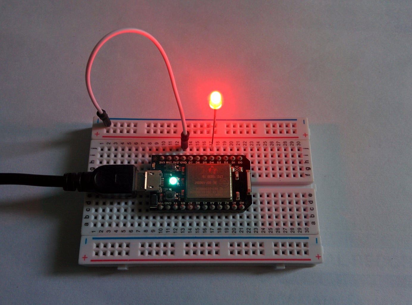
Connect the led to digital pin 0, if you are using my code, and don't forget to change the pin number to 0, if you are copying the code from the arduino IDE.
Code..
int led = 0; // Led attached to digital pin 0;
void setup() {
// initialize the digital pin as an output.
pinMode(led, OUTPUT);
}
void loop() {
digitalWrite(led, HIGH); // turn the LED on (HIGH is the voltage level)
delay(1000); // wait for a second
digitalWrite(led, LOW); // turn the LED off by making the voltage LOW
delay(1000); // wait for a second
}
Step 4: Flashing


The core will flash pink light at you when it receives the flash, and turn black cyan if the flash went successfully. And that's it now you got the core blinking the led attached at digital pin 0. To continue, try flashing multiple LEDs or move on with my next tutorial..
If you faced any problems leave a comment below or feel free to PM me.


