

Introduction: Telepresence Robot: Distance Sensor


Most of the sensors we have investigated so far involve navigating immediate dangers, such as things the robot crashes into or sudden drops. The distance sensor takes a different approach in sensing things far away so the robot can make informed decisions about what to do next.
The particular sensor we are using is a PING distance sensor. This sensor uses ultrasonic sound to calculate the distance of objects in space. It works on a similar principal to the edge detection sensor in that it sends out a signal -- in this case an ultrasonic sound and not LED light -- and then measures how long it takes to bounce back. By calculating how long it takes to return in relation to the speed of sound, we can calculate how far away the object is that the sound bounced off of.
This sensor works up to about 12 feet, and allows you to measure with reasonable accuracy the distance of objects over a wide area. This is not only helpful in avoiding things, but can also be used to get a basic sense of the shape of the environment. With the right code, it can even be used as a crude motion sensor. However, we are primarily using it to avoid objects.
This sensor is meant to prevent the collision switches from being triggered. The collision switches are intended to be more of a fail-safe and last resort than effective means of interacting with the world. The distance sensor is being installed to keep the robot from crashing in the first place.
This is the fifth part of a seven-part instructables series. Over the next two instructables we will be building the basic electromechanical robot platform. This platform will later be enhanced with sensors and additional control electronics.
To learn more about the topics covered in this series of projects check out the Robot Class, Electronics Class, and Arduino Class.
Step 1: Materials

You will only need one thing for this lesson:
(x1) PING ultrasonic distance sensor
Step 2: Test It Out

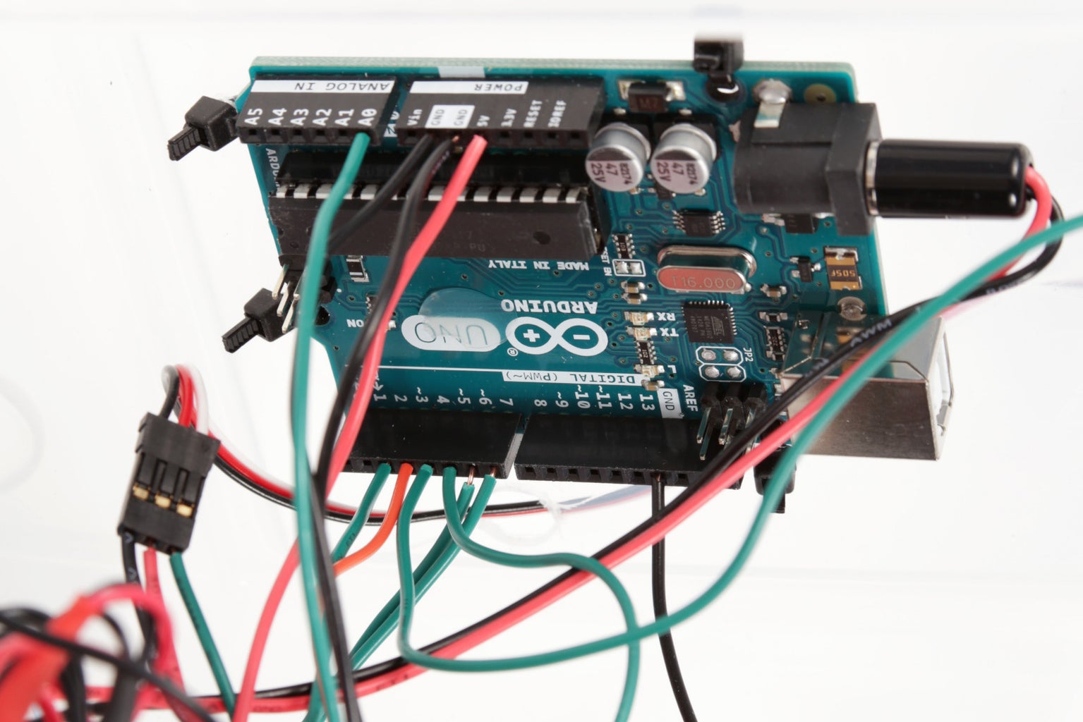
Plug the sensor into a breadboard and wire its pins to the Arduino as follows:
Ping 5V to Arduino 5V
Ping Ground to Arduino ground
Ping Signal to Arduino digital pin 4
The Ping sensor "talks" to the Arduino by sending a series of rapid high (5v) and low (ground) pulses to the digital input pin. The Arduino is able to interpret these special pulses and calculate the distance of objects. It is a bit like someone is communicating with the Arduino in morse code by tapping on a switch that is connected to the input pin, except it is happening really - really - really - fast.
High and low pulses is the basis of all digital communication and logic. When people talk about computers running on 1s and 0s, this is what they are referring to.

Once the wires are connected, upload the following code and open the Serial Monitor:
Step 3: Mark and Drill


Place the sensor on the front of the plastic box and mark it's mounting holes onto the box.
Also make markings on the box just next to the each of the board's mounting holes. We need these second holes to zip tie the sensor to the box.
Drill all of these marks with an 1/8" drill bit.
Step 4: Solder Wires


We're going to need to solder 12" solid core wires to each of the pins on the sensor.
To make this easier, we are going to first tin the pins on the sensor and each of the wires. What tinning means is to melt a little bit of solder onto a surface to prepare it to be soldered later. We do this because solder likes to stick to other solder. If both surfaces already have solder on them, it will make them easier to join.
Once everything is tinned, solder the green wire to SIG, the red wire to 5V and the black wire to GND.
Step 5: Drill Another Hole


Drill a 3/16" hole somewhere on the front surface of the box in order to pass the sensor wires through to the Arduino.
I chose to hide this hole behind the lid handle.
Step 6: Affix the Sensor

Remove the lid from the box.
Using the holes that you just drilled, zip tie the sensor to the front of the box.
Step 7: Connect the Arduino
Pass the green and black wire through the 3/16" hole in the front of the box.
Connect the green wire to digital pin 4 and the black wire to ground.
Step 8: Program the Arduino

Upload the following code to the Arduino:
Step 9: Power Wire


Put the lid on and close the case up.
Again we find outselves with another 5V connection, and no socket on the Arduino to plug it into. We're going to need to solder the red wire from the PING sensor to the 5V connection on the switches like we did the power wire from the edge detection sensor.
Once it is soldered in place to all of the other 5V connections, use a zip tie to clean up the wires.
Step 10: Give It a Go

Power it up and let it loose.
It should now be avoiding objects that come within 10 inches of it.


![Tim's Mechanical Spider Leg [LU9685-20CU]](https://content.instructables.com/FFB/5R4I/LVKZ6G6R/FFB5R4ILVKZ6G6R.png?auto=webp&crop=1.2%3A1&frame=1&width=306)


