

Introduction: The Flexible Sensor Hand Controller


The Flexible Sensor Hand Controller makes it possible to control your projects with your finger movements via wireless communication. The flexible sensor hand controller acts as a transmitter. Also, in this project, we built the Arduino Robot Tank circuit with dual DC motor as a receiver. As a result, we have provided a Robot Tank control wirelessly with finger movements. Let's take a look at the video on "how it works?
Step 1: How It Works?
The Flexible Sensor Hand Control contains 5 flex sensors whose resistance changes upon bending. Flex sensors, also known as bend sensors, are easy-to-use sensors specifically designed to measure the amount of deflection or bending. The resistance values measured by bending are the analog values. These values are compared with the threshold values in the code and the functions are executed. Circuit uses an nRF24L01 transceiver module to communicate this data wirelessly. Of course, an Arduino Nano V3 microcontroller was used to do all this.
Let's take a closer look at the main components used in the project.
Step 2: Flex Sensor


A flexible sensor, also known as a bending sensor, is a sensor designed to measure the amount of bending. In fact, a flex sensor is basically a resistor whose resistance value changes upon bending. Since the resistance value is directly proportional to the amount of bending, it can also be called a Flexible Potentiometer.
Flex sensors are generally available in two sizes: one is 2.2″ and another is 4.5″ long. In this project, flexible sensors with a length of 4.5″ (11.4cm) were used. Of course, you can also use 2.2″ (5.5cm) long flexible sensors, it will not affect the project circuit.
Adafruit Long Flex sensor - https://amzn.to/3mAgQXh
For more technical details see: https://lastminuteengineers.com/flex-sensor-arduino-tutorial/
Step 3: Transceiver Module


- nRF24L01+ Transceiver Module
- Frequency Range 2.4 GHz ISM Band
- Communication Range: 800+ m (line of sight)
The nRF24L01 + transceiver module allows two or more Arduino boards to communicate with each other wirelessly and remotely. A transmitter and a receiver circuit are required to provide communication. An address (array of bytes) is created for two nRF24L01 modules to communicate. It communicates over this address and transfers data. If you are having any problem with getting it work, try adding a 10uF capacitor in parallel to the Vcc and Ground pins. Or you can use the power adapter module produced for the nRF24L01+
A popular library called RF24 is used to interface with the nRF24L01 transceiver module. RF24 Arduino Library for nRF24L01 Module: https://github.com/nRF24/RF24
For more technical details see: https://lastminuteengineers.com/nrf24l01-arduino-wireless-communication/
Step 4: Breadboard Circuit for Transmitter


It is quite easy to connect a flex sensor to an Arduino. You need to connect a 10kΩ resistor with the flex sensor to create a voltage divider circuit. Then the point between the resistor and the flex sensor is connected to the Analog ADC input of an Arduino.
The shared breadboard circuit diagram shows how to connect 5 flex sensors and the nRF24L01+ transceiver module. Build your circuit according to this circuit diagram.
1x Arduino Nano V3 - https://amzn.to/3FuNvVV
1x NRF24L01 Transceiver - https://amzn.to/3sAPOTB
5x Flex Sensor - https://amzn.to/3mAgQXh
1x 10uF Capacitor - https://amzn.to/3JlM3aE
5x 10K Resistor - https://amzn.to/3ptPVhZ
Step 5: Transmitter Source Code


A transmitter code that reads sensor data from Arduino's ADC pin and prints the output to the serial monitor. For most projects, that's pretty much all that's needed. Upload the shared source code. If all is well, you should see a change in resistance and estimated angle calculation as you bend the flex sensor.
Attachments

Step 6: Printed Circuit Board for Transmitter


A printed circuit board was designed to turn the transmitter into a useful prototype. In this way, the prototype can be easily mounted on a glove.
Printed circuit boards are plates with conductive paths on the surface for mounting electronic circuit components. To get the PCBs, simply upload the shared "Gerber file" (pcbway.com/project/shareproject/The_wireless_flexible_sensor_hand_controller) to PCBWay and create an order. High-quality PCBs will arrive in a few days depending on the shipping address.
The Flex Hand Controller needs a few components. Easy solderable components. Place and solder components according to shared reference designator.
Required Components for Transmitter Circuit:
10uF Capacitor - https://amzn.to/3JlM3aE
Header Male - https://amzn.to/3JdFgzL
Header Female - https://amzn.to/3Eo7BzC
Power Jack 5.5MM - https://amzn.to/3FqLlq6
10K Resistor - https://amzn.to/3ptPVhZ
On/Off Switch - https://amzn.to/3ewq1U9
Soldering Iron Kit - https://amzn.to/3emwl0J
Step 7: Mount the PCB to the Glove
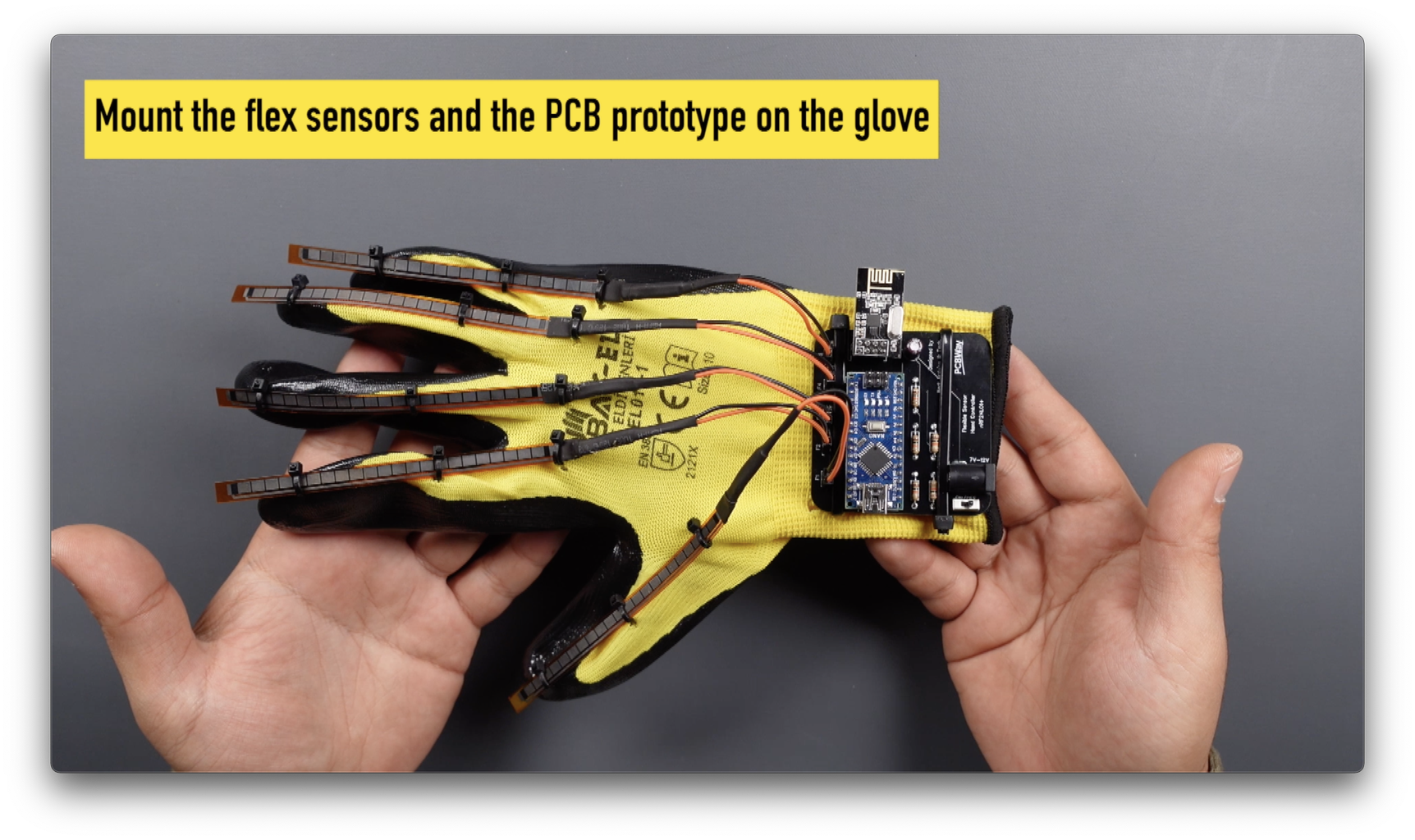


After PCB soldering is complete, mount the prototype using a cable tie on a simple glove. Then upload the shared transmitter code. Then view the values of bending movement of all fingers from the serial monitor and save them for later use.
Step 8: Receiver Circuit and Code


On the receiver side, you can control many types of motors. In this project, double DC motor robot tank circuit was built and controlled. After installing the shared schematic, upload the receiver code by updating it with the flex sensor values you obtained. Then start the show!


