

Introduction: The Joystick Hand Controller and DIY Camera Slider


The Joystick Hand Controller makes it possible to control the projects using two-axis values (directions of movement of joystick knob). Also, in this project we made a DIY camera slider and controlled it wirelessly with the Arduino Joystick Hand Controller. Let's take a look at the video on "how it works?".
Step 1: How It Works?
The Joystick Hand Controller includes a two-axis joystick component. The analog values measured on the X and Y axes are compared with the threshold values determined in the source code and the functions are run. The joystick hand controller acts as a transmitter, it uses the nRF24L01 transceiver module and enables communication wirelessly.
The joystick controller contains three main hardware:
- The nRF24L01 + transceiver module
- Two-Axis Joystick
- Microcontroller
Step 2: Transceiver Module


- nRF24L01+ Transceiver Module
- Frequency Range 2.4 GHz ISM Band
- Communication Range: 800+ m (line of sight)
The nRF24L01 + transceiver module allows two or more Arduino boards to communicate with each other wirelessly and remotely. A transmitter and a receiver circuit are required to provide communication. An address (array of bytes) is created for two nRF24L01 modules to communicate. It communicates over this address and transfers data. The nRF24L01 module is a bit tricky to use especially since there are many cloned versions in the market. If you are having any problem with getting it work, try adding a 10uF and 0.1uF capacitor in parallel to the Vcc and Ground pins. Also make sure the 3.3V supply is clean and does not have any noise coupled in it.
A popular library called RF24 is used to interface with the nRF24L01 transceiver module. RF24 Arduino Library for nRF24L01+ Module - https://github.com/nRF24/RF24
For more details - https://lastminuteengineers.com/nrf24l01-arduino-wireless-communication/
Step 3: Two-Axis Joystick

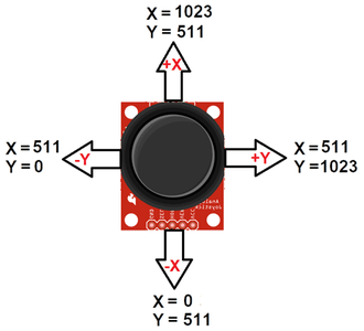
When we listen the word “Joystick” we think of Game controllers. If we talk about Electronics there are many useful application of Joystick. These type of module are mostly used in Arduino based DIY projects and Robot Control. As we know, the module gives analog output. We can use a Joystick Module with Arduino, Raspberry Pi and any other Micro-controllers. We just have to connect the axis Pins VRx and VRy to the ADC Pins of the micro-controller.
The output range is fixed for each direction. The below image shows, the value of analog output for X and Y axis based on the movement of Joystick Module in all four directions (+X, -X, +Y, -Y). You will also get some analog value when moving the knob diagonally.
Step 4: Microcontroller


- Arduino Pro Mini
- 3.3V 8 MHz
Arduino Pro Mini was developed for applications and installations where space is premium and projects are made as permanent set ups. The Pro Mini does not have a built-in USB input, so a serial converter (FTDI) is used to upload the source code. It is an easy process. For more detail about Arduino Pro Mini - https://www.arduino.cc/en/pmwiki
The Pro Mini does not have a built-in USB input, so a serial converter (FTDI) is used to upload the source code. It is an easy process. Arduino Pro Mini 3.3V version is used in the project, so make sure to set the power jumper on the FTDI module to 3.3V!
Step 5: Prototype (Printed Circuit Board)


A printed circuit board was designed to turn the project into a useful prototype. Printed circuit boards are plates with conductive paths on the surface for mounting electronic circuit components. To get the PCBs, simply upload the shared "Gerber file" (https://www.pcbway.com/project/shareproject/) to PCBWay and create an order. High-quality PCBs will arrive in a few days depending on the shipping address.
The Joystick Hand Controller needs a few components. Easy solderable components. Place and solder components according to shared reference designator.
Required Components for Joystick Transmitter Circuit:
- Arduino ProMini https://bit.ly/3wmSLFK - https://amzn.to/3jUwufV
- nRF2L01 Module https://bit.ly/3yl5Y2X - https://amzn.to/3ArlY5C
- Joystick Module https://bit.ly/3xiAvyf - https://amzn.to/3wbbRyt
- Capacitor Kit https://bit.ly/3yjhhZC - https://amzn.to/3jHS8Uc
- Resistor Kit https://bit.ly/369DD3G - https://amzn.to/3ypp6Nd
- Switch 8x8mm https://bit.ly/3xiIhIH - https://amzn.to/3AkiYYu
- LED Kit https://bit.ly/3hCGCXN - https://amzn.to/3AroZCY
- 18650 Holder https://bit.ly/3qPlce3 - https://amzn.to/2TyowOA
- 18650 Li-ion Battery
Step 6: Breadboard Prototype for the Joystick Hand Controller


I'm attaching a circuit diagram here in case you want to test and experience the Joystick Hand Controller. You can then order a PCB to turn your breadboard circuit into a professional prototype.
One nRF24L01 power adapter is needed in the breadboard circuit, in addition, Arduino Nano V3 microcontroller is used for easier programming. So you don't have to use an FTDI module when trying out the breadboard circuit.
- Arduino Nano https://bit.ly/3wiBxsK - https://amzn.to/3AsUnkb
- nRF24L Adapter https://bit.ly/3jGF5SZ - https://amzn.to/3dJvZRT
Step 7: Transmitter Source Code

Upload the shared Transmitter source code (https://create.arduino.cc/editor/mertarduinotech) using the FTDI module. Before the source code is uploaded, the board selection should be determined according to the Arduino Pro Mini version (3.3v/8MHz) used. Also, install the library named RF24 to interface with the nRF24L01 transceiver module. RF24 Arduino Library for nRF24L01+ Module - https://github.com/nRF24/RF24
Step 8: DIY Camera Slider Construction


On the Receiver side of the project we made a DIY Camera Slider. I used linear rail, rail shaft and linear block bearing for camera slider construction. All 8mm in diameter. You can adjust the length of the linear rail according to your wishes, but the longer the length of the linear rails, the precise adjustment will be required to prevent jamming.
In addition, 1 meter GT2 belt, 2x GT2 16 tooth pulleys and several bearings were used. One of the pulleys was used for the stepper motor and the other was used to provide the movement of the free side of the belt.
We positioned the camera slider construction on several wooden plates. Wooden plate dimensions are completely up to you, the important thing is to create an area where you can place the motor and circuit.
The wood was painted with acrylic to give it a metallic color, resulting in a realistic metal look.
Construction and all other details are shown step by step in the project video.
Required Hardware for DIY Camera Slider
2x Linear Rail https://bit.ly/2TyrToI - https://amzn.to/369v7Sp
2x Rail Shaft https://bit.ly/3xl3Zf1 - https://amzn.to/3AvsmZE
2x Linear Block https://bit.ly/3dJHyID - https://amzn.to/3whrhkK
Wooden Plate https://bit.ly/3hdxwSk - https://amzn.to/3dJaaBP
Screws Nuts https://bit.ly/3hdxQk0 - https://amzn.to/3dK2fEu
Screw DSLR https://bit.ly/3dJ7Qux - https://amzn.to/3dJ7LXL
Step 9: Receiver Circuit and Source Code


On the Receiver side of the project we made a DIY camera slider and controlled it with the joystick hand controller. You can assign one of the joystick axes (X and Y) to motor direction control and the other to motor speed control.
The A4988 driver for the stepper motor control:
- The A4988 is a micro-stepping driver for controlling bipolar stepper motors.
- The A4988 provides five different step resolutions: full-step, haft-step, quarter-step, eight-step and sixteenth-step. It has a potentiometer for adjusting the current output.
- Logic voltage is 3 to 5.5 V Maximum current 2A (with cooling)
- Continuous current 1A (without cooling)
A4988 Stepper Driver Pinout:
- The VDD and Ground (GND) pins connect to the 3V or 5V of the microcontroller.
- The 1A and 1B pins will be connected to one coil of the motor and the 2A and 2B pins to the other coil of the motor.
- The VMOT and Ground (GND) connect to power supply from 8V-35V for powering the stepper motor. Use decoupling capacitor with at least 47 μF for protecting the driver board from voltage spikes. The Step and Direction (DIR) are the pins use for controlling the motor movements. The Direction pin controls the rotation direction of the motor. The Step pin control the micro-steps of the motor and with each pulse sent to this pin the motor moves one step.
- The SLEEP Pin and a logic low puts the board in sleep mode for minimizing power consumption when the motor is not in use.
- The RESET pin uses to a predefined Home position. The reset pin is a floating pin. If it is not going to be used in the program, it must be connected to the SLEEP pin to bring it high and enable the board.
Step motor and Driver Connections:
- Use the drive in "Full Step Mode" so leave the "3 MS" pins disconnected.
- Connect the "Direction" and the "Step" pins of the drive to the pins number 3 and 4 on the "Arduino Board”.
- Connect the "Ground" and the "3V" pins to powering the board.
- Use a "100μF" capacitor for protecting voltage spikes and "12V, 1.5A" adapter for powering the motor.
- Use a "NEMA 17" bipolar Stepper Motor. It's wires A and C will be connected to the pins "1A and 1B" and the B and D wires to the "2A and 2B" pins.
- Before connect the motor, should be adjust the current of the driver for the current limits of the motor. It can be do that by adjusting the reference voltage using the potentiometer on the board. Adjusted the potentiometer and measured 0.6V reference voltage. So the current limiting should be that value of 0.6*2, equal 1.2 A.
Required Components for Receiver Circuit
Nema17 Stepper https://bit.ly/2SOyQBK - https://amzn.to/3hBc4W7
A4988 Driver https://bit.ly/3qSNZi4 - https://amzn.to/3hsfb2M
Arduino Nano https://bit.ly/3wiBxsK - https://amzn.to/3AsUnkb
nRF2L01 Module https://bit.ly/3yl5Y2X - https://amzn.to/3ArlY5C
nRF24L Adapter https://bit.ly/3jGF5SZ - https://amzn.to/3dJvZRT
Breadboard https://bit.ly/3qJckqi - https://amzn.to/3hxX5MN
Power Jack https://bit.ly/3dHkLNy - https://amzn.to/3jMOokF
Jumper Wires https://bit.ly/36bYH9L - https://amzn.to/3Ap5lHv
Receiver Code:
First, we have to define the Step and Direction pins. The pins number 3 and 4 on the Arduino Board. They are named stepPin and dirPin and the setup section we have to define them as an outputs. Download the DIY Camera Slider Receiver code https://create.arduino.cc/editor/mertarduinotech/receiver
Participated in the
Arduino Contest


