

Introduction: Traffic Lights Using Arduino


In my childhood I remember asking mom to buy traffic lights toy. At that time it fascinated me as I learned how to behave on the street. At that time the toy was with incandescent lamps as LEDs were not yet available and my mom said that it is too expensive as she would need to work a whole day to earn for such toy.
Nowadays I was amazed to hear that kids are still attracted by traffic lights toy. I suggested instead of buying one, to make it with an Arduino.
Buy the way, such an exercise to program traffic lights on Arduino is given to physics students during electronics course.
Step 1: Checking Other Designs
First it is a good idea to search Youtube on the subject.
There are simple designs with just 3 LEDs or more serious with 12 LEDs and 4 corners of the intersection.
Some designs have bare LEDs sticked into electronics breadboard. Some other have nicely decorated boxes.
The video of traffic lights made in the present tutorial is here:
Step 2: Assembling the Circuit.

Assembling was done with connector wires so that LEDs can be removed.
Extra two GND pins were soldered to Arduino pinout.
Step 3: Programm Code
// Arduino traffic lights
void setup() {
pinMode(2, OUTPUT); // Green
pinMode(3, OUTPUT); // Yellow
pinMode(4, OUTPUT); // Red
}
void loop() {
digitalWrite(2, HIGH); delay(10000); // Green on
for (int i=0; i < 3; i++){ // Green blink 3x
digitalWrite(2, LOW); delay(500);
digitalWrite(2, HIGH); delay(500);}
digitalWrite(2, LOW);
digitalWrite(3, HIGH); delay(3000); // Yellow
digitalWrite(3, LOW); digitalWrite(2, LOW);
digitalWrite(4, HIGH); delay(10000); // Red
digitalWrite(3, HIGH); delay(3000); // Yellow
digitalWrite(3, LOW); digitalWrite(4, LOW);
}
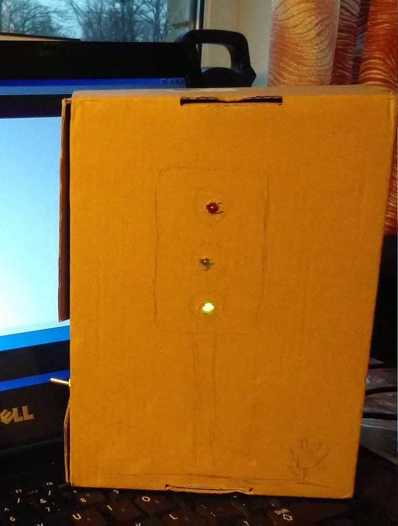
Step 4: Assembling

Simplest solution was to fix everything in a cardboard box with hot-melt glue and to decorate the box using color markers.
AA batteries vere used to power the scheme. The scheeme can be powered through the USB.
Step 5: Conclusion
Design was welcomed with joy by a kid who got it as a present and by his friends.
He will paint it at home with color markers.
I told to write down the cable colors and where each wire is connected.
In future it might be a good idea to add the possibility to change timing speed with a potentiometer or buttons.


