

Introduction: USB Breakout Board


Here's a handy USB Breakout Board that makes measuring USB 2.0 current draw, data, or whatever, a snap.
Step 1: Bill of Materials (for One USB Breakout)

USB B Receptacle
USB A Receptacle
2 Row, 8 Position Breakaway Header
Single Row, 36 Position Breakaway Header (enough for 3 boards)
4 x 0.1" pitch jumpers (I have hundreds of these laying around scavenged from old PC circuit boards)
PCBs from OSH Park (includes 2 extra PCBs)
Step 2: Get the PCBs

Download the Gerber files, upload to OSH Park, and place an order.
A few weeks later you'll get your circuit boards in the mail and you're ready to build a USB Breakout. You'll have two extra PCBs to give to a couple of friends or build extra USB Breakouts.
Gerbers also available at https://github.com/TechUnboxed/USBBreakout
Attachments

Step 3: Build It Up


Solder the parts in the board.
For the most part the parts can only go in one way, but the USB Breakout can be built in a few different configurations. The single rows of headers on either side of the board can be soldered on the bottom for use with a solderless breadboard, on the top as test points, or omitted completely. The optional single-row headers make the board easier to use and a little more versatile.
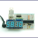
Step 4: Using the USB Breakout


The USB Breakout can be used for any type of USB 2.0 measurement. Good luck and enjoy.
UPDATE: The USB Breakout Board is now a shared project on OSH Park. Boards can be ordered directly at http://oshpark.com/profiles/Ktulu


