

Introduction: USB Night Light (LM385 Light Sensor)


A few months ago, I've ask for a free samples of some TLC555 and LM385 chips from Texas Instruments. A few weeks after that, a friend of mine asked me to build a nightlight for her. I never really made the effort to build one until now, so here is my variant of a simple LM358 light sensor running off USB power.
Step 1: Materials and Tools


Materials that I've used in this build:
x1 Lm358 Dual Op Amp IC (DIP8 package) + socket
x4 SMD LEDs salvaged from a unused LCD(I couldn't figure out how to use it so well time to disassemble it)
x1 LDR (Light Dependent Resistor)
x1 2N3904 NPN Transistor
x1 Variable Resistor (I used 5Kohm, salvaged)
x1 USB A Male connector
Resistors:
x1 10Kohm
x1 1Kohm
x2 220ohm (one should be enough, but i used two)
circuit board (I used pad per hole ones)
Heatshrink tubing (for protecting the LDR from shorting when bending it)
Tools that I used:
Wire strippers
Soldering Iron + solder
Hot glue gun + hot glue (for insulating the solder side to prevent shorts)
Needle nose pliers
Step 2: Testing


Before actually soldering the circuit together, I put the components together on a breadboard. After making sure that the circuit works, I start soldering them together.
Note: In this circuit only one Op Amp in the chip is used.
Step 3: Heat Up the Iron and It's Time to Solder!


Start up the soldering iron and prepare the components, making sure they all all present. I start by desoldering the SMD LEDs from its flex circuit (no picture) and then I continue by soldering the USB connector to the board, then the socket, then the LED's, transistor, resistors, LDR(put the heatshrink tubing over one of it's leads), variable resistor. After that, I wire all of the components together.
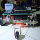
After all is done, I checked for shorts and test it by plugging it to a usb power source and it comes alive.
Step 4: Protection and Touchups.


Just showing pictures of it running before I actually did the insulating process. The hot glue was used to insulate the board and diffuse the LED's.
Step 5: Finished.


Now everything is done so I played with it for a while and took more pictures. I took about one hour or so(Breadboarding, soldering, toilet breaks, etc.) for this build.
This is a good project for beginners in electronics and soldering (aside from 555 circuits) so I recommend people who want to learn about electronics and soldering to build this. Make your own design based on what you have on hand and have fun!

Participated in the
Tech Contest

Participated in the
Hand Tools Only Contest


![Tim's Mechanical Spider Leg [LU9685-20CU]](https://content.instructables.com/FFB/5R4I/LVKZ6G6R/FFB5R4ILVKZ6G6R.png?auto=webp&crop=1.2%3A1&frame=1&width=306)


