

Introduction: Using a 5 Volt Mechanical Relay


This Instructable demonstrates using a 5 volt mechanical relay as a switch to control two LEDs. There are two different wiring configurations demonstrated. The first wiring toggles two LEDs, one "on" and one "off". The second wiring switches the two LEDs both "on" or both "off".
The following video demonstrates these two different wiring configurations:
Things you will need:
- Two 9 volt batteries
- Two LEDs (preferably different colors)
- Two resistors (with enough resistance to protect the LEDs - 330 Ohm should be fine)
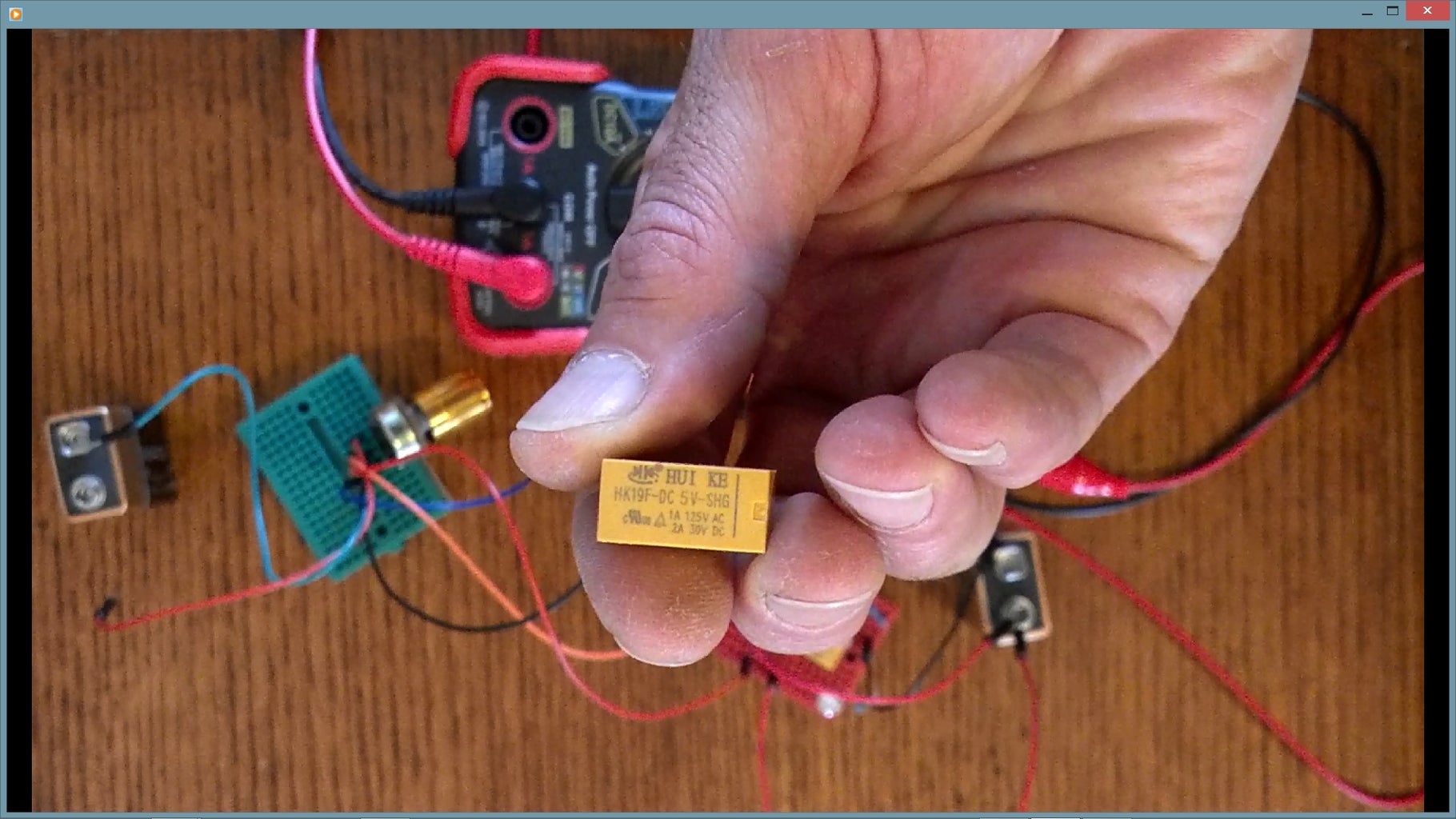
- One 5 volt mechanical relay - the one used in this demonstration is HK19F-DC 5V-SHG (see picture above). You can find these on amazon: http://www.amazon.com/uxcell%C2%AE-Coil-Power-Rela...
- One 1K potentiometer
- At least one breadboard to wire it all up
- A bunch of jumper wires to make the connections.
- (Optional) Multi-meter to measure the potentiometer output voltage.
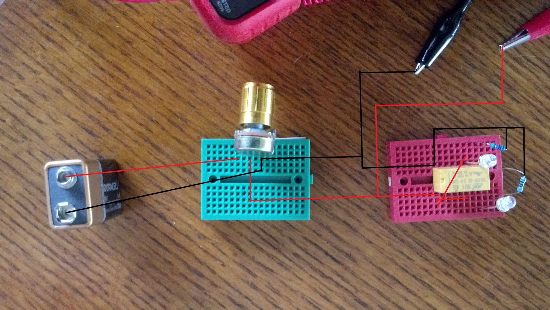
Step 1: Wiring Configuration 1 - ON/OFF or OFF/ON


The first wiring uses two 9 volt batteries. One battery is connected to a 1K potentiometer. The output of the potentiometer is connected to the relay in order to control the switch. Another 9 volt battery is used to power the LEDs. When the potentiometer is turned one way the resistance is reduced causing the current and voltage to increase. When enough power is applied, the relay coil becomes energized and flips the relay switch. This causes the power to switch from one LED to the other. So the originally "ON" LED turns off and the originally "OFF" LED turns on. So there is always one LED "ON" and one "OFF".
Turning the potentiometer the opposite direction increases the resistance causing the voltage and current to drop. Once the power drops to a certain point, the relay coil will no longer be energized and allow the circuit to open (turn off). When the relay returns to the "OFF" position, the LEDs return to their original configuration. There will still be one LED off and one on but they will have switched.
Step 2: Wiring Configuration 2 - OFF/OFF or ON/ON

The second wiring configuration uses only one 9 volt battery. The battery is connected to the potentiometer. The output of the potentiometer is connected to the relay switch. So far, the same as the first wiring. However, instead of using a separate 9 volt battery to power the LEDs, only one battery will be used. The battery connected to the POT is used to power the relay and the LEDs after the relay switch has flipped. So, the power is going through the potentiometer which will allow for some dimming of the LEDs. After the relay switch has flipped, both LEDs will turn on and get brighter if the potentiometer continues to turn and reduce resistance. Turn the potentiometer in the opposite direction (increasing resistance), the LEDs will turn off due to lack of power and then the relay will flip, opening the circuit, turning the system off.
Step 3: Measurements and Observations
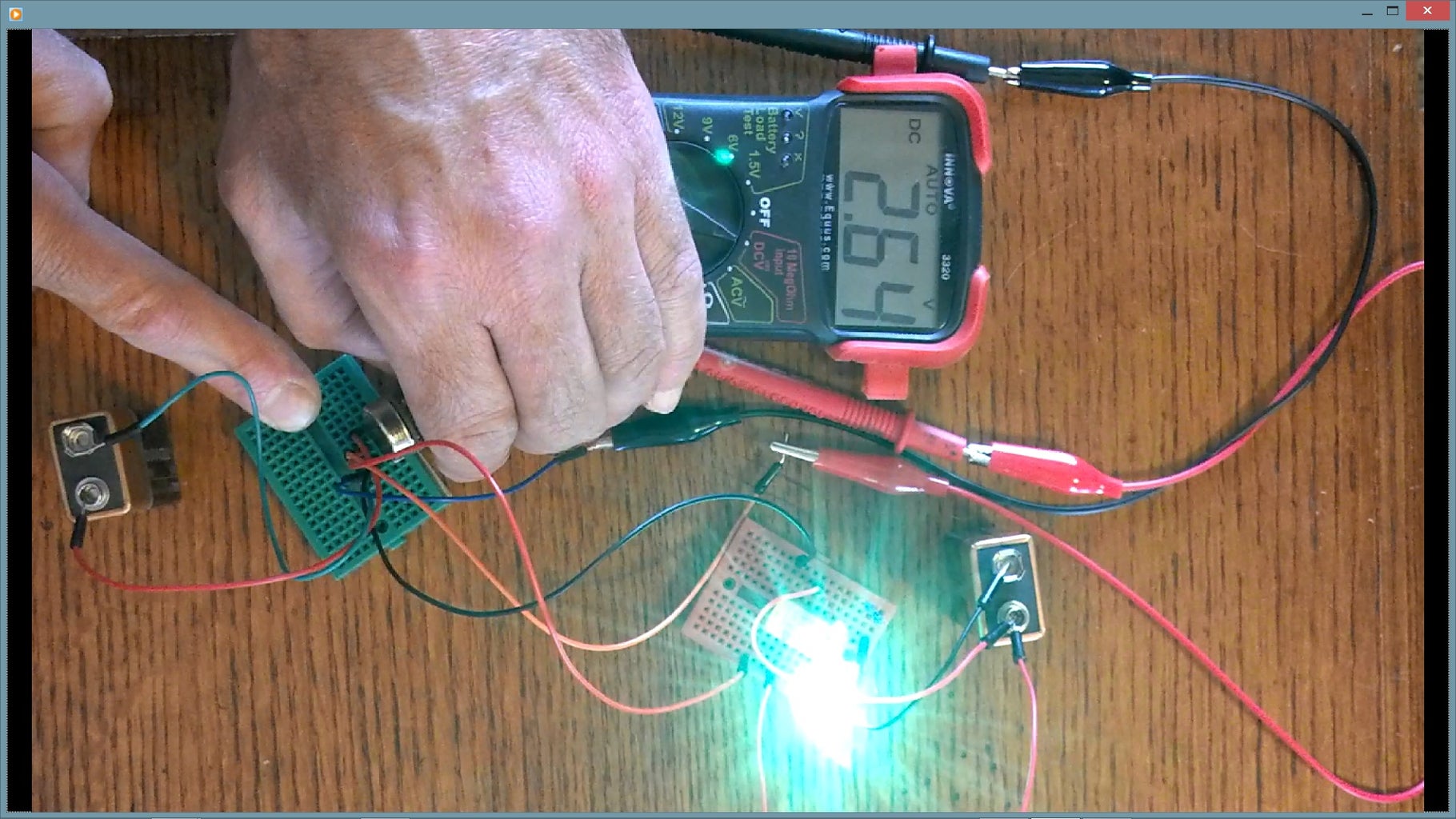

Using the optional multi-meter you can determine what voltage causes the relay to switch OFF and ON.
First, turn the potentiometer all the way off, so that there is maximum resistance and the relay switch is not energized and essentially "OFF".
Then, turn the potentiometer up slowly, decreasing the resistance. At the same time watching the multi-meter to see at what voltage the relay switch flips. It's a mechanical switch so you can actually hear the switch flipping. In this demonstration, the relay turns on at about 2.6 volts (it's probably closer to 2.5).
Now, turn the potentiometer the opposite direction, slowly increasing the resistance. Watching the multi-meter as the voltage drops paying attention to when the relay turns off (again you will hear the mechanical switch flip). In this demonstration the relay turns off at around .6 volts (probably closer to .5). So there is about a 2 volt range between turning off and on.
Understanding this information helps us know how the relay will function in a real world application. For example, I intend to use this type of relay in one of my projects. The project is a portable solar power supply. It has a 12 volt battery that is connected to a simple charge controller. The charge controller consumes energy all the time so I want to shut it off at night when the battery is not being charged. A 5 volt relay connected to the solar panels is used to control the connection between the battery and charge controller. So, in the morning, when the solar panels produce enough power to flip the relay, the charge controller will connect to the battery and commence charging. Likewise, at night, when the solar panel power drops, the relay switch will flip off and the battery will be disconnected from the charge controller. This way the charge controller does not consume and waste energy at night. So this type of connection is one power source controlling another (Wiring Configuration One).
Wiring Configuration Two can be used in the same project as a load controller. A 12 volt relay might be more suitable but a 5 volt relay could be used with the right sized resistor. The relay would sense when the voltage drops to 10.5 volts and shut off the load so that no more power can be drained from the battery. This helps protect the battery from over discharge which can shorten the life of the battery. Then when the relay senses the voltage has gone up to 12.5 it will turn the load back on again and it can then drain back down to 10.5, the cut off point. Notice the 2 volt on/off span we measured earlier with the multi-meter. It works nicely in this application.


