

Introduction: Very Simple and Cheap Guitar/Bass Distortion Pedal


Here, I will teach you how to make a very simple 1 transistor low power guitar pedal. (I designed the circuit diagram and PCB). This circuit can be ran off old 9v batteries (In version 2, I was running it off a really cheap mobile phone power supply, 5v SMPS) that still have a charge above 1.5v meaning you won't have to throw them out!
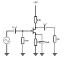
Edit:If you increase the input capacito (the 100n capacitor) more bass frequencies can flow through the common emitter amplifier, causing more of the distorted effect.
Also, if you change the bias of the transistor (swap the 100k Resistor for a much higher value, e.g. 680k or more, the transistor will be forced to asymmetrically clip, increasing the distortion. Go to the last page for sound clips :)
In my new circuit, I use a 470k resistor for the bias resistor.
AGAIN! A problem arises at the cost of extra distortion. The attack of the instrument may get chopped off(silenced in this case). With my bass, this only seems to happen when I am using the slap bass technique.
Step 1: Find the Parts!
Firstly, to make the pedal you obviously need the parts! Most of the parts can be found in the base of a CFL light bulb. I already had the parts to make this and have customised the parts to my liking. In the schematic, it says the input capacitor is 100n. It doesn't matter what value the input capacitor is really aslong as it is within the range of: 47n - 100uF. All the capacitors mainly do is affect the level of distortion at the output (as well as the diodes at the output!). For my transistor, I used a BC337 (On my old one) because I had it at the time but I'm sure that any NPN transistor will work fine. At the output stage, different kinds of diodes produce different levels of distortion. I used simple 1N4001 diodes (The most common diode around) But to get different kinds of output waves, many combinations of diodes exist such as schottky diodes (To produce a lower amplitude giving a nice germanium diode sound due to both germanium and schottky conducting at lower voltages) or rectifier and schottky diodes (Lopsided wave) etc. I tested the input down to 1.5v. at this voltage, it had some quite high distortion and a bit of an annoying hum but worked fine overall. Therefore, a 9v battery would last extremely long is the circuit works down to 1.5v.
The input and output capacitors depict the frequency response of the circuit e.g. The lower the input capacitor, the more bass is cut. This is good if your looking for a nice Trebly overdrive. Otherwise, this capacitor can be increased to any value. The values of these components doesn't particularly matter if your just looking for a simple distortion circuit.
The 100Ohm Resistor that is just above the Diodes can be removed to make the output wave much 'Harsher'.
The 100K resistor at the base of the Transistor mainly depicts the gain. Increasing this resistor increases the gain up to a certain point (It changed the bias of the transistor).
Edit: I have now included my new circuit diagram for the much more RAW! Distortion. Go to the last page for sound samples!Unfortunately, with this new circuit, the distortion isnt so epic at 1.5v :(
For this new circuit, i used a BC337-25, a much more gainier transistor.
Step 2: Build the Product
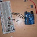
I build this on a breadboard as i have not had time to produce the PCB yet. The parts for this pedal are really cheap (around 50p if postage doesn't have to be paid) and can be made of almost any parts available.
Step 3: Final Product

Here's what my final product looked like! (Sorry for the blurry picture, I had to take it on my phone)
Step 4: What Both Versions Sound Like
Here is an sound file of how my overdrive pedal sounds. The first riff is clean and the second riff is the same as first just distorted. Thanks for reading!
Revised sounds:
The reason that the amplitude is lower on the second sound clip, that is because that was my bass clean through my amp. No volume changes or moving away the microphone. My setup was the same for each recording. The amplifier was on:
0 Bass
0 Treble
For both recordings.
My bass used was a Warwick Rockbass Streamer 2P'up Version.
Edit: On my new recordings, the moded circuit is used. I will include both a bass and guitar recording :) (excuse my TERRIBLE guitar playing :P)
My amplifier was recorded with a simple condensor module through using Audacity :)
Same bass, Guitar is a: Cheapo Spider Fender copy (I play bass not guitar!)
The files: "Guitar file" and "Bass File" Are the new versions :D


