

Introduction: Video Game Controller With Arduino


Ever wanted to create a video game controller for playing your favorite game? Or perhaps even a rapid fire button allowing you to pres a computer button 100 times a second. Well, in this instructable I'm going to show you how to create a video game controller (for a game on the PC/Comp). This controller is customizable as per your game and can be made with any Arduino. The difference between many other such implementations and this one is that most implementations are restricted to only 32u4 based boards (micro, leonardo etc) whereas this will allow more common Arudino uno and nano. This is because the typical implementations directly use Arduino libraries to simulate keyboard functions, while this uses an additional "Processing" program to talk to Arduino and do the work.
Step 1: Components
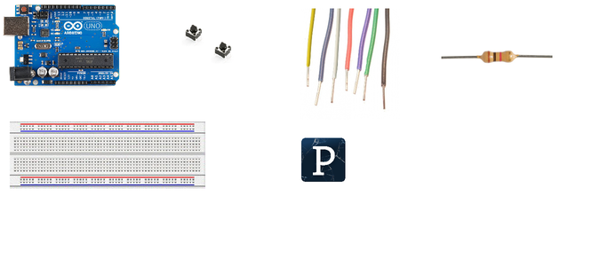
Components:
- Arduino (any)
- Pushbuttons (the number required depends upon what game you want to play. Each button represents a key you want to press.)
- Resistors (As pull down resistors. Any thing above 500E should do. For each push button.)
- breadboard (to make something permanent, use perf board)
- jumper wires
Software:
- Arduino IDE (of course)
- Processing IDE (you can download it from here- https://processing.org/download/)
Step 2: How It Works
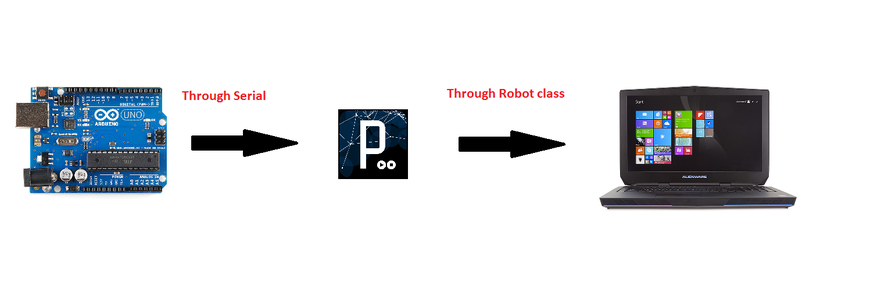
In order to make the controller, the pressing of the computer keys needs to be simulated when you press the keys on the controller. The simplest way to do this is to use the inbuilt keyboard libraries of arduino, but as mentioned before, it is restricted to 32u4 boards (Due, Leonardo, Micro). So if you have a non 32u4 board (like uno, nano) it gets a little bit harder. To overcome this, "Processing" program is used. When a button on the video game controller is pressed, the Arduino sends some specific String through serial port. For example, if the 'up' button is pressed, the Arduino will send Serial.println("Up");. The processing program reads this string and simulates the pressing of a up arrow key using the java Robot library.
Step 3: Making the Circuit


The controller is very easy to make. All you have to do is connect one terminal of the switch to +5V and the other terminal to a digital pin (for example D12) as well as GND through the pull down resistor. Repeat the connecting of the switches for all the buttons that you need. And remember to place the switches in such a way that it is convenient to play.
Here is the Arduino code. (The Processing code required is found in next section). It needs to be modified to suit to your application. My program is going to simulate the pressing of the "UP" key when D12 push button is pressed and "DOWN" key when D11 push button is pressed. How to modify the program is given in detail in the second last step, though it is actually very easy and may not really need the explanation.
Note: You would notice that I am sending "Up:" instead of just "Up". This is because I had some trouble reading the string ending character in my Processing code and just chose this easy way to simply read until I get a ":".
const int UpButton = 12;
const int DownButton = 11;

void setup(){
   Serial.begin(9600);
   pinMode(UpButton, INPUT);
   pinMode(UpButton, INPUT);
}

void loop(){
   if(digitalRead(UpButton) == HIGH){
	Serial.println("Up:");//It doesn't matter what you print. Just have a colon at the end to make it easier to parse the string.
	delay(100);
   }
   if(digitalRead(DownButton) == HIGH){
	Serial.println("Down:");
	delay(100);
   }

}
/*Add or subtract to the code for your application. Just make sure you do a Serial.println()
* with a colon when you want to simulate a keypress.
*/
Step 4: Processing


Now, we will talk about the "Processing" part. Processing is used to actually simulate the pressing of a key. Processing is just java but doesn't need to be manually compiled; and running it is also easier. The code uses the Robot class which allows programmatic control of the keyboard. So, for example, when the keyPress(VK_UP); method is called it would simulate the pressing of the up key (VK_UP is just the constant for the up arrow key). The below "Processing" code basically reads the string which is sent by Arduino over serial port. (Remember that we simply want to read the data till ":" since we are sending the string followed by a colon from Arduino). Depending upon the contents of the string the code will simulate the pressing of the appropriate keyboard key (if the string is "Up" it will press the UP key).
import processing.serial.*;
import java.awt.AWTException;
import java.awt.Robot;
import java.awt.event.InputEvent;
import java.awt.event.KeyEvent;
import javax.swing.KeyStroke;
Serial MyPort;
String KeyString = "";
void setup()
{
System.out.println("Hi");
size(700, 500);
MyPort = new Serial(this, "COM3", 9600);// My Arduino is on COM3. Enter the COM on which your Arduino is on.
MyPort.bufferUntil('\n');
}
void draw(){//Not really necessary
background(0, 0, 0);
fill(255, 0, 0);
text("Press any key", 100, 175);
}
void serialEvent(Serial MyPort)throws Exception {
KeyString = MyPort.readStringUntil('\n');
KeyString = KeyString.substring(0, KeyString.indexOf(':'));//The string is split. the whole string leaving the colon is taken
System.out.println(KeyString);//prints the serial string for debugging purpose
Robot Arduino = new Robot();//Constructor of robot class
switch(KeyString){
case "Up" :
Arduino.keyPress(KeyEvent.VK_UP);//presses up key.
Arduino.keyRelease(KeyEvent.VK_UP);//releases up key
break;
case "Down" :
Arduino.keyPress(KeyEvent.VK_DOWN);
Arduino.keyRelease(KeyEvent.VK_DOWN);
break;
}
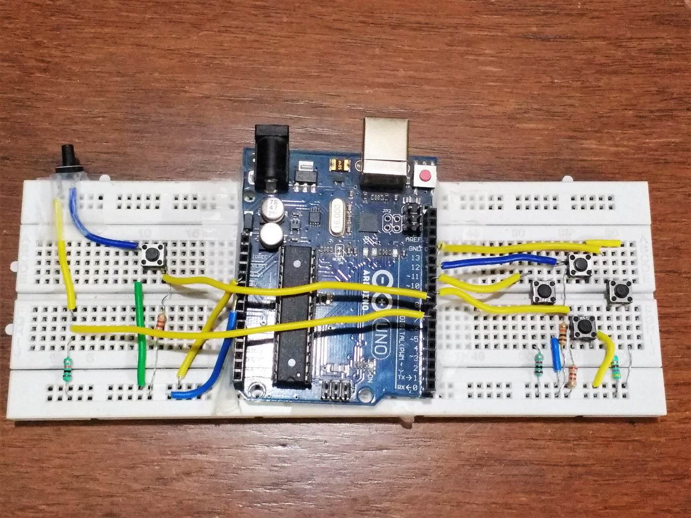
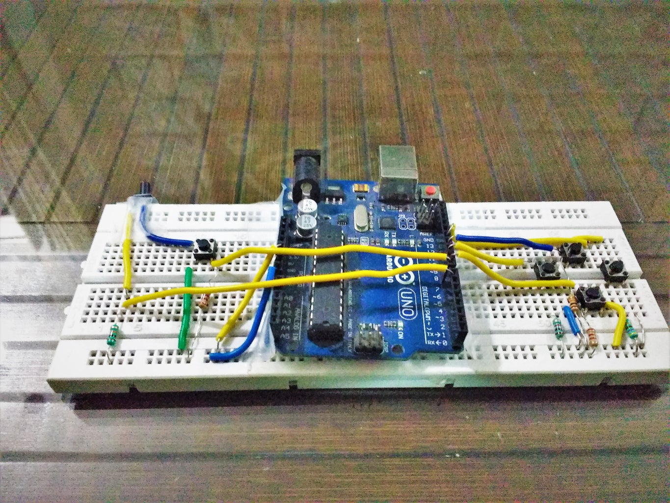
}To test the circuit, simply connect the Arduino to your device and run the processing code. When you press the button connected to pin 12, the up key will be pressed and similarly the down key would be pressed for pin 11. You can see this easily if you keep your cursor in an editor (you can see the cursor moving up and down). And this in itself is a very basic gaming controller. It can be used to play games like Chrome's T-rex game. [In the image of my controller you will see that I have positioned my up and down key slightly differently (along with a bunch of other keys, but the wiring is the same)].
Step 5: Making Your Custom Controller
To make your own controller for the games you want to play, make your circuit like described earlier. Then copy the Arduino code given earlier and add you buttons against appropriate pins in a similar fashion.As an example of how to modify the code, given below is an example for adding the left and right key.
const int UpButton = 12;
const int DownButton = 11;
const int LeftButton = 10;//the left button is connected to D10
const int RightButton = 9;//the right button is connected to D9
void setup(){
   Serial.begin(9600);
   pinMode(UpButton, INPUT);
   pinMode(UpButton, INPUT);
   pinMode(LeftButton, INPUT);
   pinMode(RightButton, INPUT);
}
void loop(){
   if(digitalRead(UpButton) == HIGH){
	Serial.println("Up:");//It doesn't matter what you print. Just have a colon at the end to make it easier to parse the string.
	delay(100);
   }
   if(digitalRead(DownButton) == HIGH){
	Serial.println("Down:");
	delay(100);
   }
   if(digitalRead(LeftButton) == HIGH){
	Serial.println("Left:");
	delay(100);
   }
if(digitalRead(RightButton) == HIGH){
	Serial.println("Right:");
	delay(100);
   }
}
Now, to modify the java code (for Processing), use the sample given earlier. You can find all the keycodes here .
//The below code is an extension to the one given in the 'processing' step to add the functionality of simulating right and left key
//After Switch case statement
case "Right" :
       Arduino.keyPress(KeyEvent.VK_RIGHT);
       Arduino.keyRelease(KeyEvent.VK_RIGHT);
       break;
case "LEFT" :
       Arduino.keyPress(KeyEvent.VK_LEFT);
       Arduino.keyRelease(KeyEvent.VK_LEFT);
       break;
If you want do press a key repeatedly (like if you want to send the UP key 10 times upon pressing the Up key just once) below is an example
case "Up" :
for(int i = 0; i < 10;  i++){
  Arduino.keyPress(KeyEvent.VK_UP);
  Arduino.keyRelease(KeyEvent.VK_UP);
  }
break;
I hope this gives you a good idea of how to make your own controller (if you have any questions, please do post in the comments).
Step 6: The Sopwith Controller


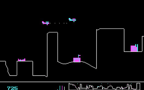

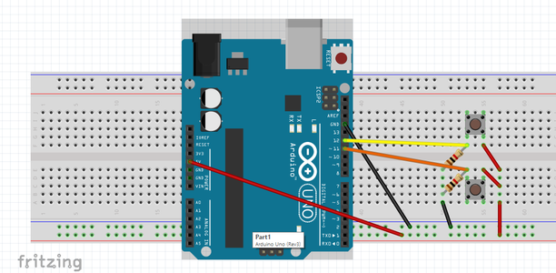
If you are interested, just as a reference, this is the controller I made for the game Sopwith. You can play it here. It is a WWI DOS game featuring a Sopwith biplane. The sopwith is supposed to shoot enemy planes/buildings/tanks. The controls for the game are (, = UP / = DOWN . = rotate 180 x = acceleration b = Bomb Space = Fire (bullets)). The controller fritzing schematic is given above. The codes for the same are given as well. The controller works really well and is fun to play the game with it. One drawback however is that it has a slight lag.
I hope you enjoyed this instructable. Please feel free to give any advice or suggestions on how I can improve this instructable/project.


Participated in the
Invention Challenge 2017


