Introduction: W5300 & STM32 Based Smart Home Hub


A smart home is a hardware system that enables connection and communication between other devices on the home automation network. These devices include thermostats, light bulbs, wall outlets and switches, door locks, energy monitors, window coverings, appliances, motion sensors, etc. While these devices provide convenient functions to users, such convenience may come at a greater cost, such as the leakage of the user’s private information. With an intelligent hub, all of these smart devices can be controlled using a single app.
The smart home hub is a hardware device that acts as the central point of the smart home system and can sense, process data, and communicate wirelessly.
According to a recent study, on average, 10 smart-home devices were deployed in U.S. houses in 2020. By 2025, nearly 75 billion devices will be installed. The proliferation of smart-home devices is mainly due to the convenience that users can easily access the devices to monitor and control their homes via smartphones and Internet access. However, this convenience comes at a cost. Specifically, the wide use of smart-home devices risks the breach of user privacy. An adversary with information about the usages/states of smart-home devices could obtain sensitive and private information about the users and their activities. i.e., what sensors are triggered or when the sensors are used. These device states often contain the users’ activities in their homes which, in turn, the adversary can use to initiate further offenses, e.g., burglary, with the information. In fact, cybercriminals are increasingly targeting smart-home devices.
This project demonstrates the details of a smart home hub for user privacy and accessibility, enabling an adversary to infer smart home events and user activities by only sniffing encrypted network traffic to/from a target home. More importantly, my insight to design is that users’ activity can routinely trigger smart devices so that an adversary can identify and learn distinct patterns in the network traffic despite being encrypted. The adversary can infer users’ activities in the smart home by analyzing the event-triggered times and distinct patterns in the network traces.
Features of the System
This smart home hub enables you to monitor and control your smart home devices by maintaining security. The following are some important functionality of the project:
- Can monitor the voltage, current, power, energy, frequency, and power factor and alert the user in case of any abnormality.
- Can monitor the temperature, humidity, and air quality of the inside of the house.
- Users can monitor the inside of the house remotely by the connected camera through a smartphone application or web browser.
- Users can monitor the status of any appliance in the house.
- Users can control any connected appliance remotely from the smartphone app or from the web browser.
Watch the Project Demo
GitHub Code link: https://github.com/taifur20/smart_home_hub
The original post is here: http://maker.wiznet.io/Taifur/contest/wiznet%2Dpowered%2Dsmart%2Dhome%2Dhub/
Supplies


For making the project following hardware components are required.
- WIZnet - W5300-TOE-Shield
- Seeed - Grove - Air quality sensor v1.3
- Seeed - Grove Beginner Kit for Arduino-Old Version
- Seeed - Grove - Serial Camera Kit
- Seeed - Grove - 4-Channel SPDT Relay
- Seeed - Grove DHT11 temperature and humidity sensor
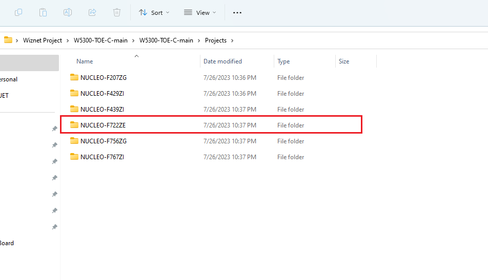
- ST - NUCLEO-F429ZI OR F722ZE Board
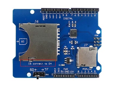
- Seeed - SD Card Shield
- PZEM004T Power Module
Following software are required:
- STM32CubeIDE
- MQTT.fx
- Paho MQTT
Step 1: Preparing STM32 Nucleo Board


Soldering Pin Headers to STM32 Nucleo Board
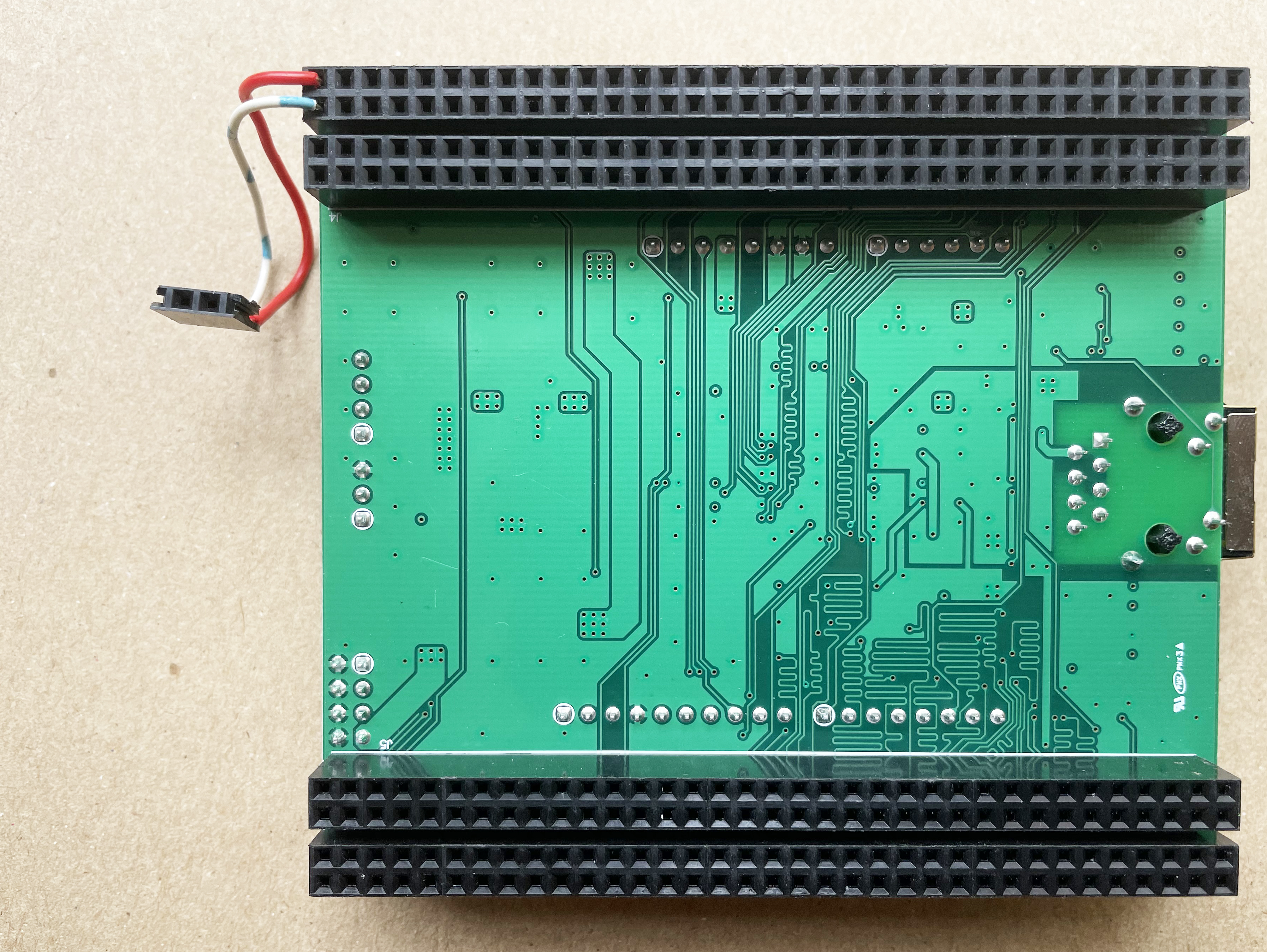
Your STM32F722ZE Nucleo board may not come with the pre-soldered male pin headers. In that case, you need to solder double line male pin header to both sides of the Nucleo board. These pin headers will be used to connect the W5300-TOE-SHIELD with the Nucleo Board. I soldered the pin headers on both sides as shown in the following image.
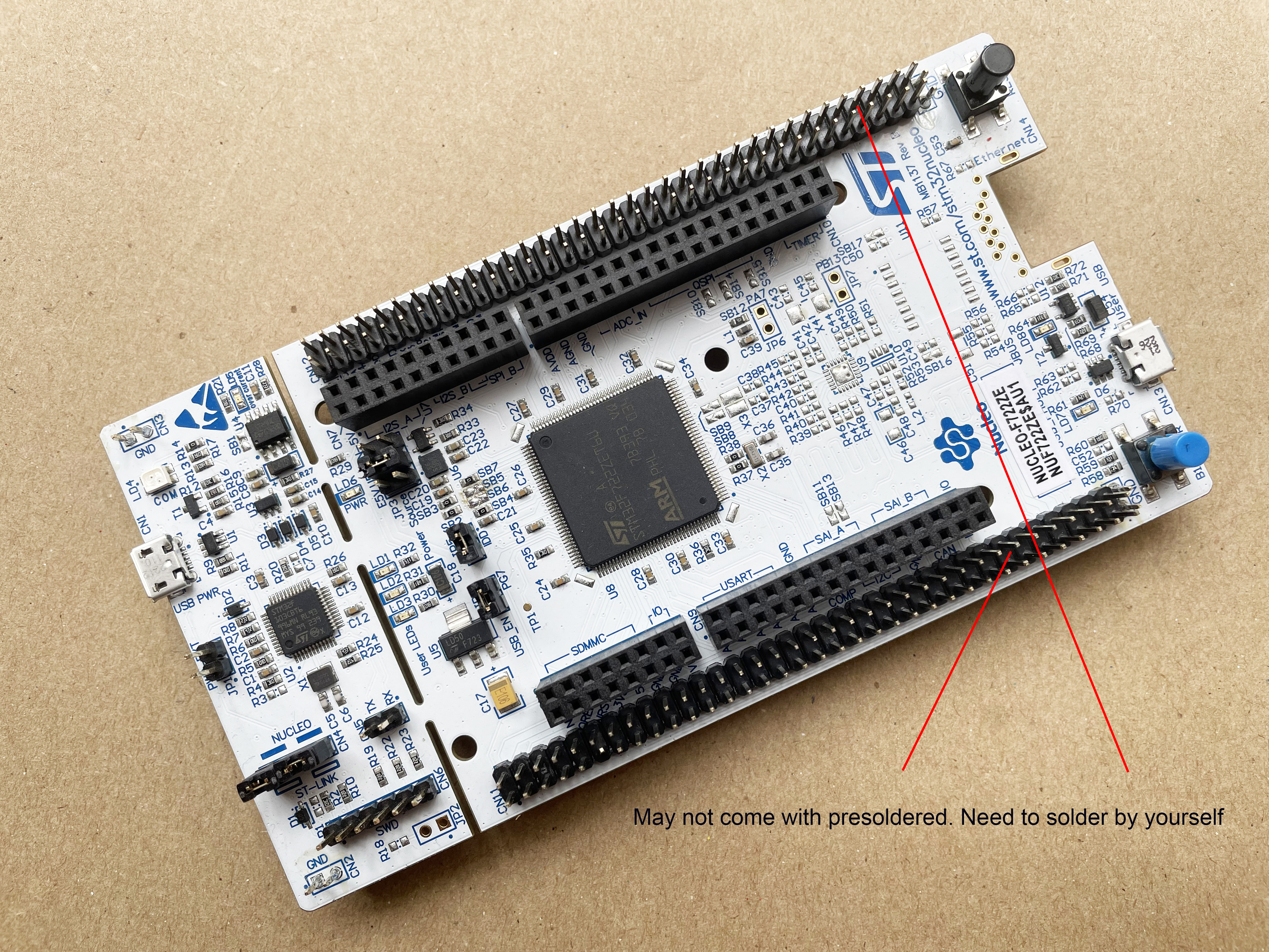
If you don't have a NUCLEO-F722ZE board the NUCLEO-F207ZG, NUCLEO-F429ZI, NUCLEO-F439ZI, NUCLEO-F756ZG, and NUCLEO-F767ZI should also work but I did not test it in those board.
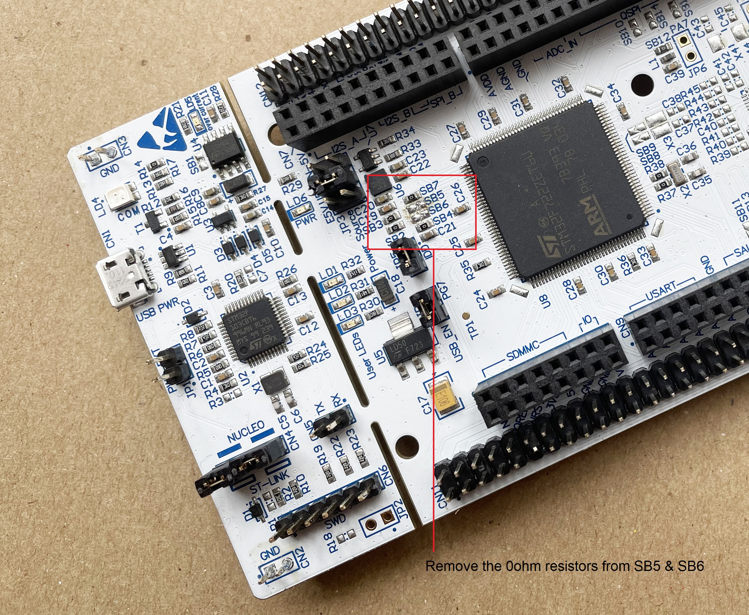
Removing SB5 and SB6 resistors from the top of the STM32 Nucleo-144 board
The default ST-LINK pin is PD8 and PD9. But these pins will be used for the FMC(Flexible Memory controller) data pin to control the W5300 built in the W5300 TOE Shield and the ST-LINK pin of the STM32 Nucleo-144 board.
Therefore, in order to use the ST-LINK of the STM32 Nucleo-144 board, we will use PC10 and PC11 instead of PD8 and PD9. So, first we need to open PD8 and PD9 of the STM32F722ZE microcontroller for W5300 TOE Shield by removing the SB5 and SB6 resistors as shown in the following image.
Step 3: Connecting TX, RX of Nucleo Board to W5300 TOE Shield
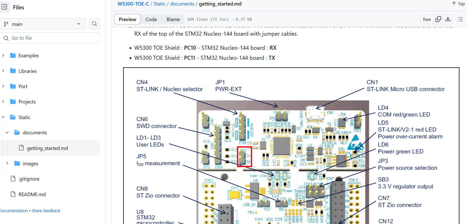
Now we need to connect PC10, and PC11 of the W5300 TOE Shield and CN5 TX, RX of the top of the STM32 Nucleo-144 board with jumper cables.
- W5300 TOE Shield : PC10 - STM32 Nucleo-144 board : RX
- W5300 TOE Shield : PC11 - STM32 Nucleo-144 board : TX
Step 2: W5300 TOE Shield With STM32 Nucleo Board


As we need to connect PC10, and PC11 of the W5300 TOE Shield and CN5 TX, RX of the top of the STM32 Nucleo-144 board I will use jumper cables.
The following image shows my jumper connection with the female pin header.
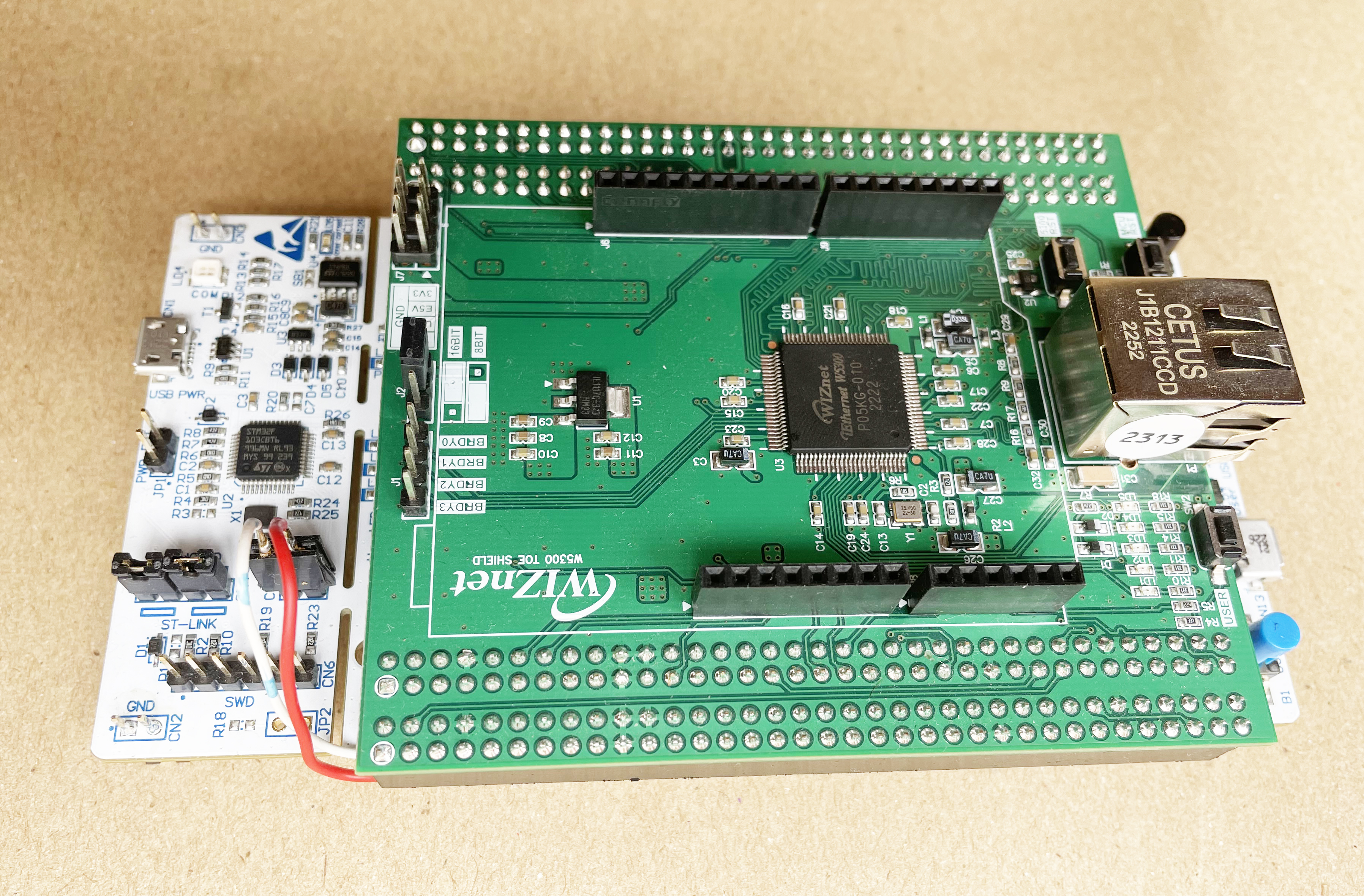
Attaching W5300 TOE Shield with STM32 Nucleo Board
The following image shows the attached Nucleo board and TOE shield.
Step 3: Connecting Grove Sensors


Attaching Grove Base Shield
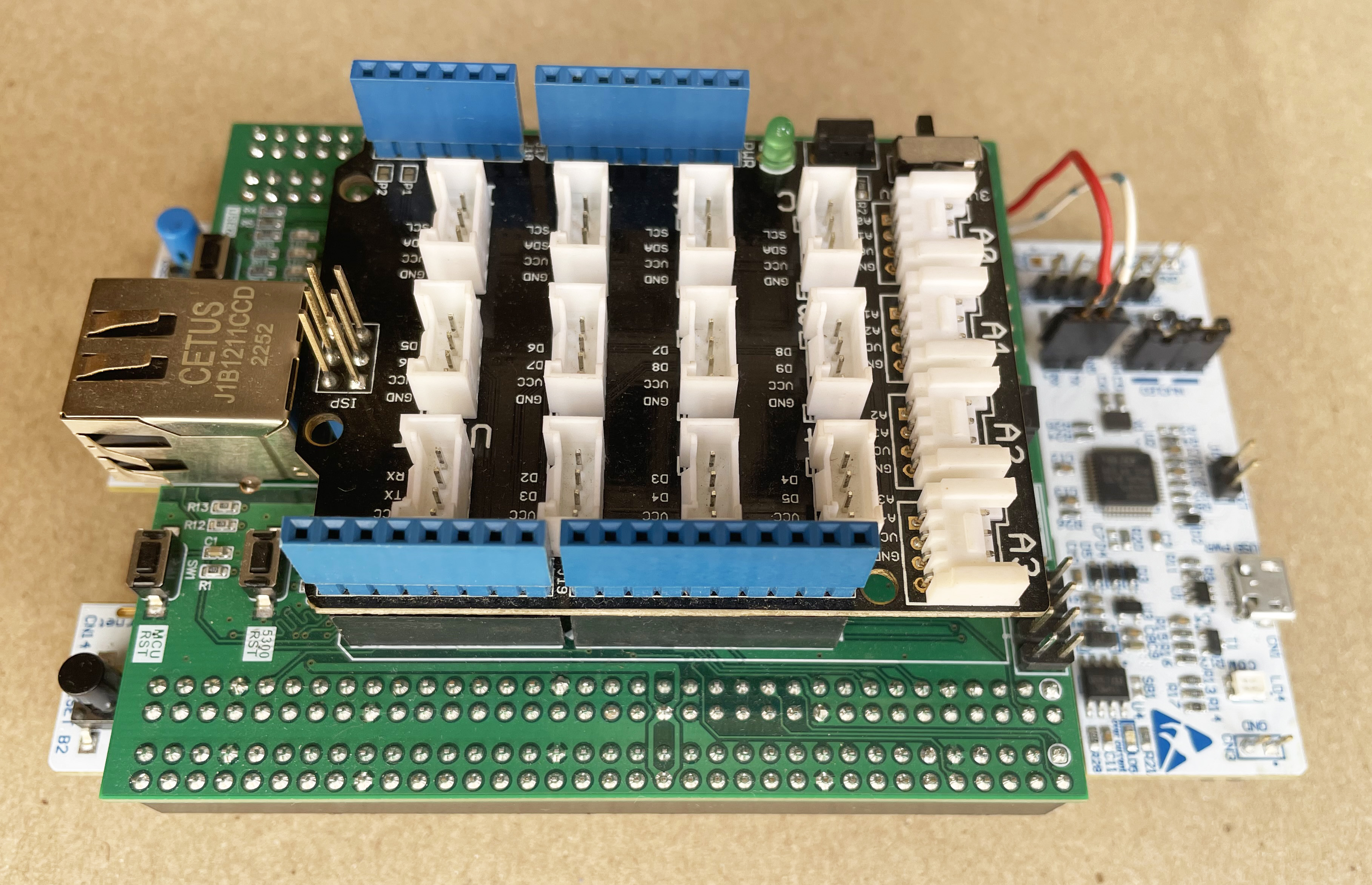
For connecting Grove sensors with the Nucleo board I am using Grove Arduino Base Shield. The base shield has several Grove connectors through which we can easily plug and play any Grove sensors or actuators. Fortunately, the W5300 TOE SHIELD has an Arduino compatible header to which we can attach any Arduino shield.
The following photo shows how I attached the Grove Base Shield with W5300 TOE SHIELD.
Connecting Grove Sensors
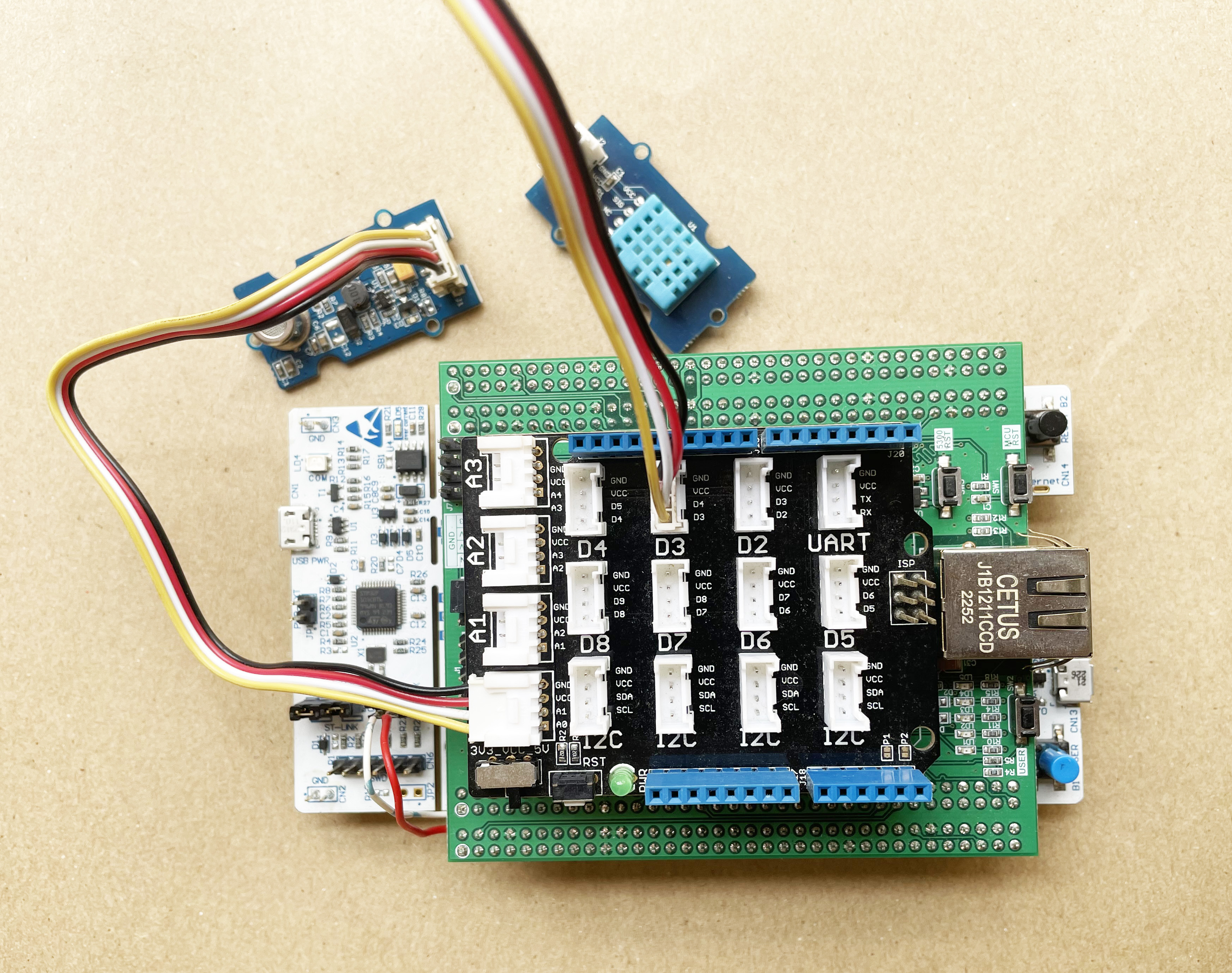
Connecting Grove sensors with the base shield is very easy. I connected the DHT-11 temperature and humidity sensor to the D3 port and the Air Quality sensor to the A0 port of the base shield. You can use different ports but you need the adjust the program accordingly.
The following photo shows the connections of the sensors.
Step 4: Connecting PZEM-004T Power Module


The PZEM-004T module is used to measure Voltage, Current, Power, Energy, Power Factor, Frequency, and Energy consumption without any calculation. It takes the voltage and current readings from CT & PT and does all the calculations for you.
The connection of the module is a bit tricky. The module sense current and voltage from the load and provides the calculated data through the serial port. So, you need to connect the module to the microcontroller through the UART port.
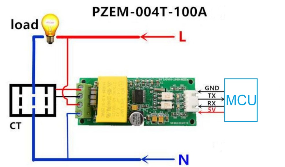
The load side should be connected with the load through CT for current sensing. The above image shows the connection with the load and the microcontroller.
The RX pin of the power module must be connected to the TX pin of the microcontroller and the TX pin of the power module must be connected to the RX pin of the microcontroller. I configured UART6 of the STM32F722ZE microcontroller for connecting the PZEM power module. The UART6 RX pin is PC7 which is the D8 pin of the Arduino header and UART6 TX pin is the PC6 pin which is the D9 of the Arduino header. I used the D8 port of the base shield for connecting the PZEM module.
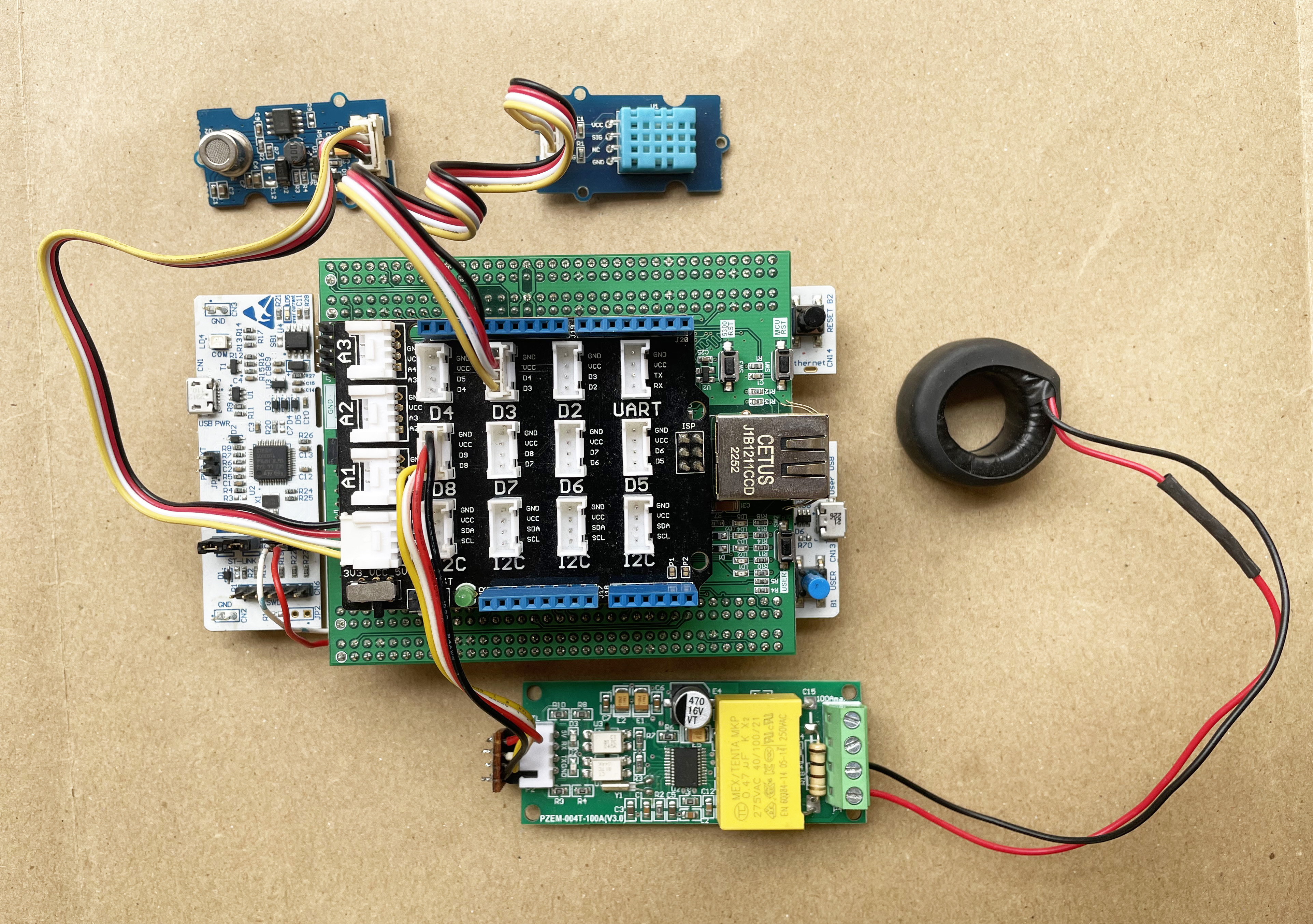
The following image shows the connection of the PZEM module with the base shield.
Step 5: Connecting Relay Module


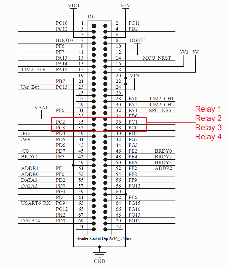
For controlling the home appliances I used 4 channel relay module in the project. Each relay will individually control one appliance. The 4 relay inputs are connected to PC0, PC1, PC2 and PC4 pins of the STM32 microcontroller. These 4 pins are available to J10 header of the W5300 TOE SHIELD. See the following image.
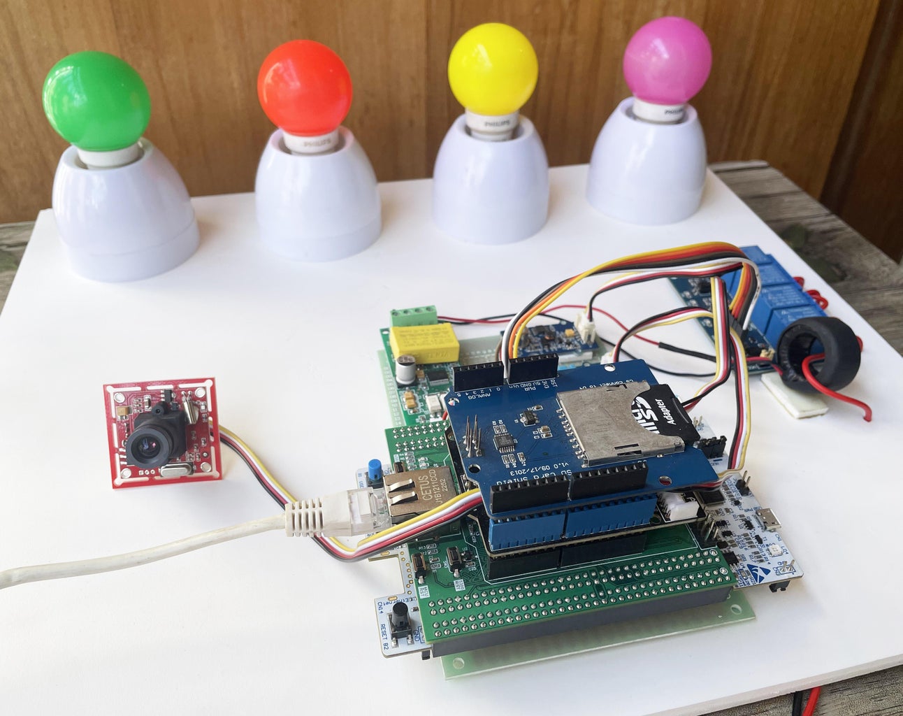
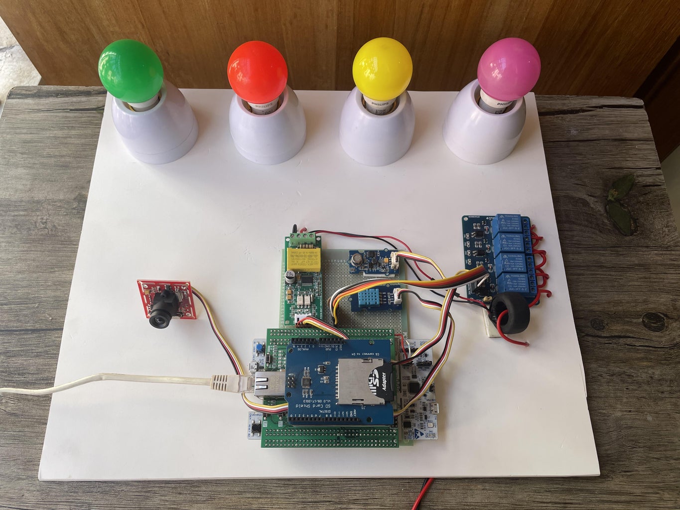
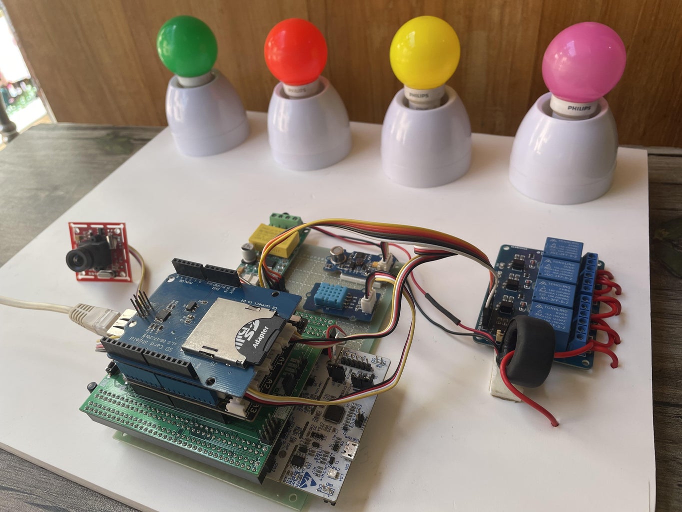
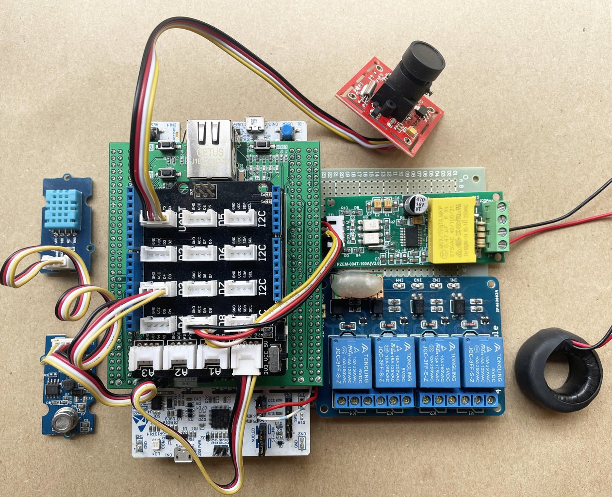
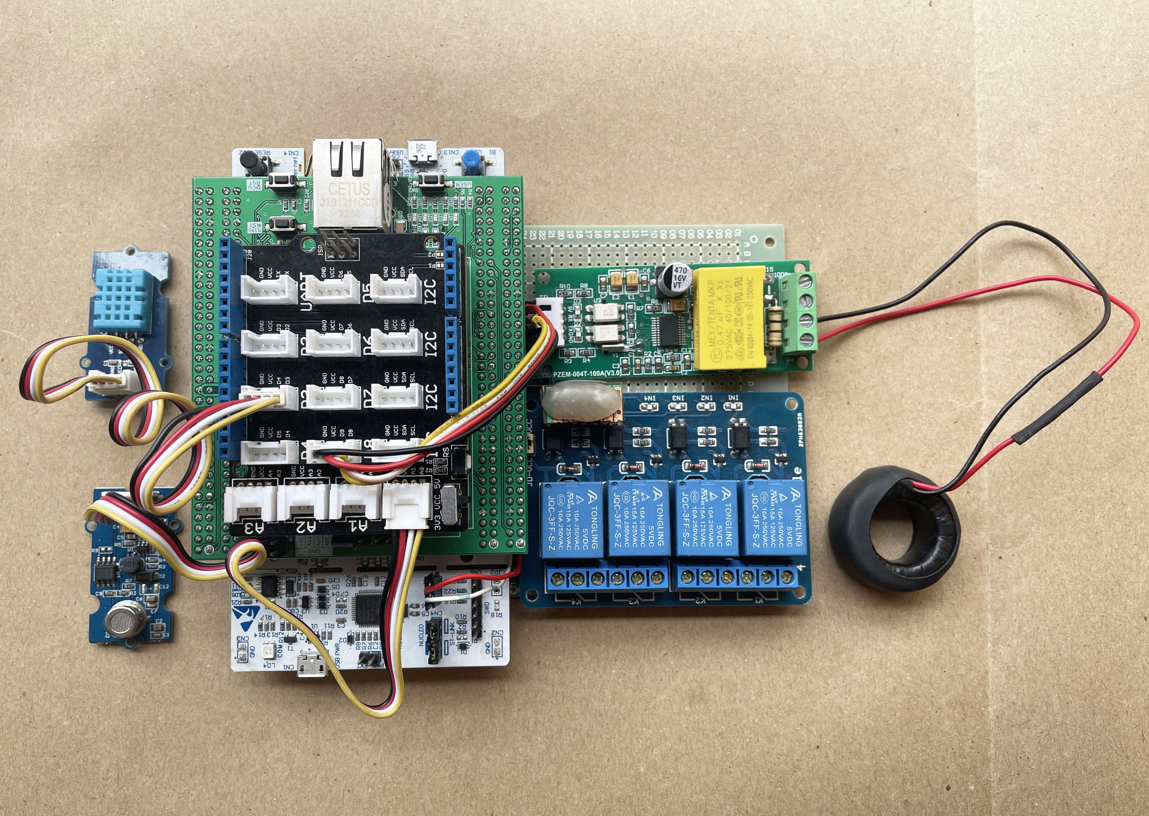
 After completing the connections I attached all the components on a perfboard as shown in the following photo.
Connecting Serial Camera
For remote watching inside the room, I attached Grove serial camera. Grove - Serial Camera Kit includes one control board and two interchangeable lenses, one is a standard lens and the other is a wide-angle lens.
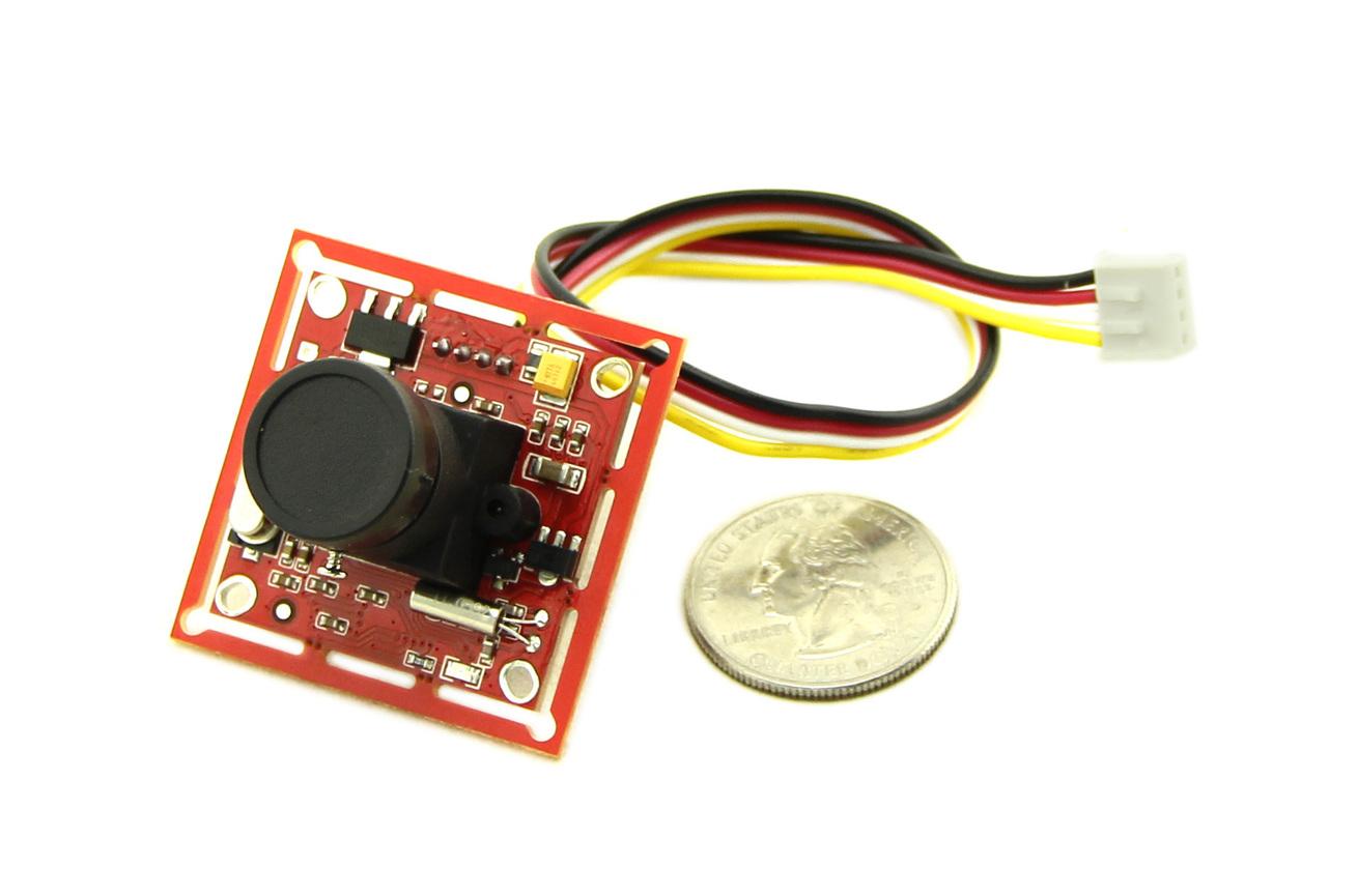
The camera communicates with any microcontroller through the serial port. Both RS485 and RS232 are supported. I am using UART7 of the STM32 Nucleo board here for connecting the camera. UART7 is configured in the PF6 and PF7 pins of the microcontroller. These two pins are available at the J10 header connector of the W5300 TOE SHIELD.

The above image shows the camera connection to the UART port of the base shield.
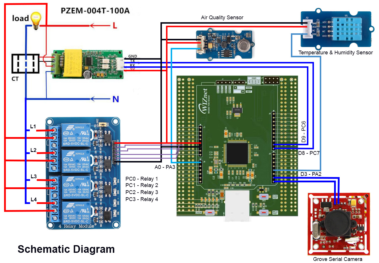
Schematic of the full project
The full schematic of the hardware is as follows:
Step 6: Firmware Development


Before going to the coding let's discuss how the system works. The brain of the system is the STM32H7 microcontroller. All sensors, ethernet TOE shield, and the camera are directly connected to the STM32 microcontroller. Sensors provide the data to STM32 microcontroller, the microcontroller uses the WIZnet W5300 ethernet module to forward the data to a cloud server using the MQTT protocol. I developed an Android application through which the sensor data can be visualized remotely. Appliances connected with the STM32 microcontroller can also be controlled from the apps. As MQTT is not good for image transfer I have implemented an HTTP server to send image data from the device to the user. Thus users will be able to monitor the inside of the house or plant remotely from the app. If you are new in MQTT let's explain it in brief. A basic understanding of MQTT is required for developing and understanding the firmware program.
MQTT in Brief
MQTT stands for Message Queuing Telemetry Transport and is a simple lightweight messaging protocol created by IBM in 1999. It was primarily designed to create a reliable machine-to-machine (m2m) communication. Now, it becomes the most popular messaging protocol in IoT application for device-to-cloud and device-to-device communication. It is hugely adopted in most of the home automation systems. Nowadays almost all cloud service support MQTT.
We use "client and server" communication technique for serving internet content, where the browser act as a client and the content is on the server. Unlike client-server, MQTT is a "client and broker" communication technique. In MQTT the clients (more accurately the devices) don't send messages directly to each other but instead communicate through a MQTT broker. The device that sends the data is called the publisher and the receiving device is called the subscriber. If two devices want to communicate with each other they become connected to a common broker through a common channel called topic. The word topic refers to an alphanumeric string that the broker uses to filter messages for each connected client. The topic consists of one or more topic levels. Each topic level is separated by a forward slash (topic level separator). For example "myhome/kitchen/temp" is a valid MQTT topic. Messages are published by things using a topic. When a thing subscribes to a specific topic that device receives the message instantly if other devices publish a message in that topic. Any device can publish to one or more topics and at the same time, it can subscribe to one or more topics. So, it is a bidirectional multi-device communication protocol. MQTT broker takes care of the security, connectivity, authentication, message delivery, and message storage. For learning more about MQTT protocol visit hivemq.com/mqtt-protocol.
The above section explained the basics of MQTT but as a maker you may ask, how do we actually use it in a device? Every MQTT broker has an address (e.g. test.mosquitto.org) and a port number (e.g. 1883). We use an address and a port number of a broker to set them on the IoT device to connect to that specific broker. For a secure connection, you may also need to use a username and password. For publishing a message you then create and use a topic in the program. The device that wants to receive that message must subscribe to this specific topic.
For example, in this project, I am subscribing "taifur/home/data" topic from the Android application to receive the sensor data from the hardware device. At the same time, I am publishing some messages to the device from the Android apps to control the appliances at "taifur/home/command" topic. From the device, I am subscribed to that topic.
Transferring image
As MQTT is a lightweight protocol it is not a good choice for publishing images. So, I implemented an HTTP server for showing images of the house to the user remotely. HTTP is a client-server communication technique where the Android app sends a GET request to the HTTP server for the image on a button press. The server returns back the image to the client.
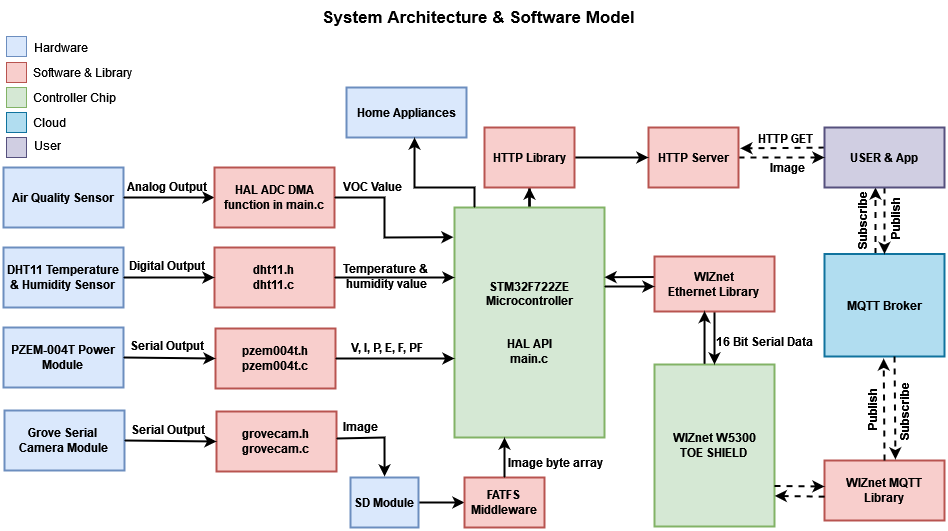
The Software Model
From the above image, you will observe that I have shown the related source file and library separately for every hardware for better understanding. I tried to make the source file of a specific sensor independent of other sensors or hardware so that you can reuse the source files for your other project.
For example, dht11.h and dht11.c are exclusively related to the reading of the temperature and humidity value from the DHT11 sensor. These two source files are completely independent of other sources. You can directly use these two source files for any of your STM32 projects for interfacing a DHT11 sensor. The same is true for PZEM-004T and Grove Serial Camera Module.
Storing images captured from the camera required an SD card. For SD interfacing I am using FATFS middleware. For giving Internet connectivity in the project Wiznet W5300 TOE Shield is used. This module requires communication to the microcontroller and WIZnet provided Ethernet library was used for this purpose. For MQTT communication I modified and used WIZnet provided MQTT library. I did the same for implementing the HTTP server.
Step 7: Creating a Project in STM32CubeIDE


Enough talk. Now let's show how I actually developed the firmware. I choose the STM32CubeIDE for the firmware development. And I get started with the code provided by the WIZnet in the GitHub link: https://github.com/Wiznet/W5300-TOE-C/.
Step 1: Downloading & Installing STM32CubeIDE
I downloaded the STM32CubeIDE from the link:https://www.st.com/en/development-tools/stm32cubeide.html and installed it on my Windows PC. Installing is very straightforward.
Step 2: Downloading necessary library and code sample
I downloaded the GitHub repository provided by the WIZnet from the link: https://github.com/Wiznet/W5300-TOE-C/. This repository contains all the required libraries for the W5300 TOE SHIELD, datasheet, schematic, getting started guide, and example project. The following image shows a screenshot of the GitHub getting started guide.
Step 3: Creating the first project
I started my project by opening the example project from GitHub for my specific board. Choose the right one based on your STM32 Nucleo board.
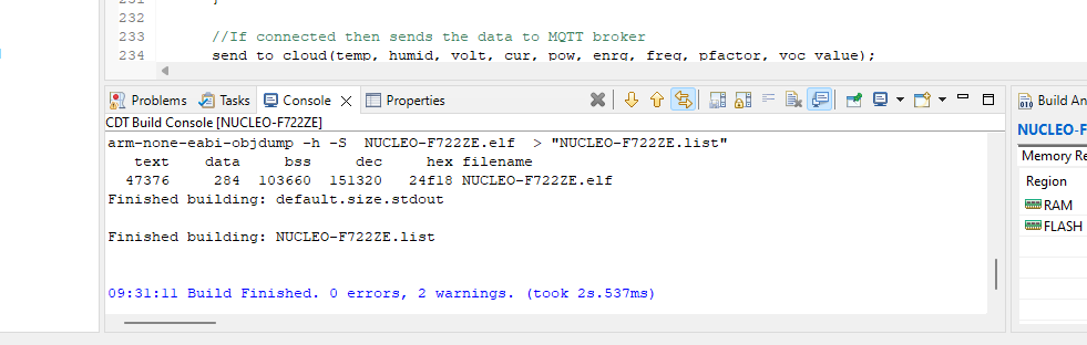
Step 4: Building the project
After importing and opening the project I recommend building the project before starting any modification so that we can get sure that everything is working.
Step 8: Testing the Code


The full source code is provided in GitHub: https://github.com/taifur20/smart_home_hub
You can directly download the repository and open it with STM32CubeIDE. After opening you can build the project and run it in your STM32F722ZE Nucleo board.
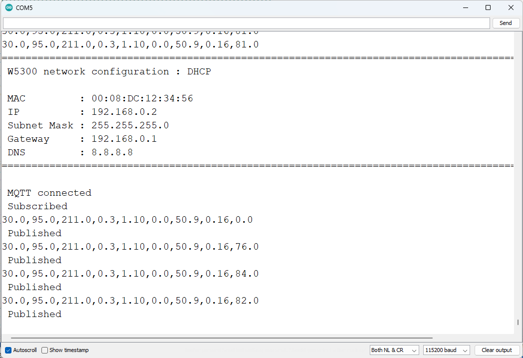
You can check the response in the serial terminal after connecting all the sensors. After a successful connection with Inetrnet & MQTT server, I got the following response in the serial terminal. I used the Arduino serial terminal. You can use any serial terminal you like.
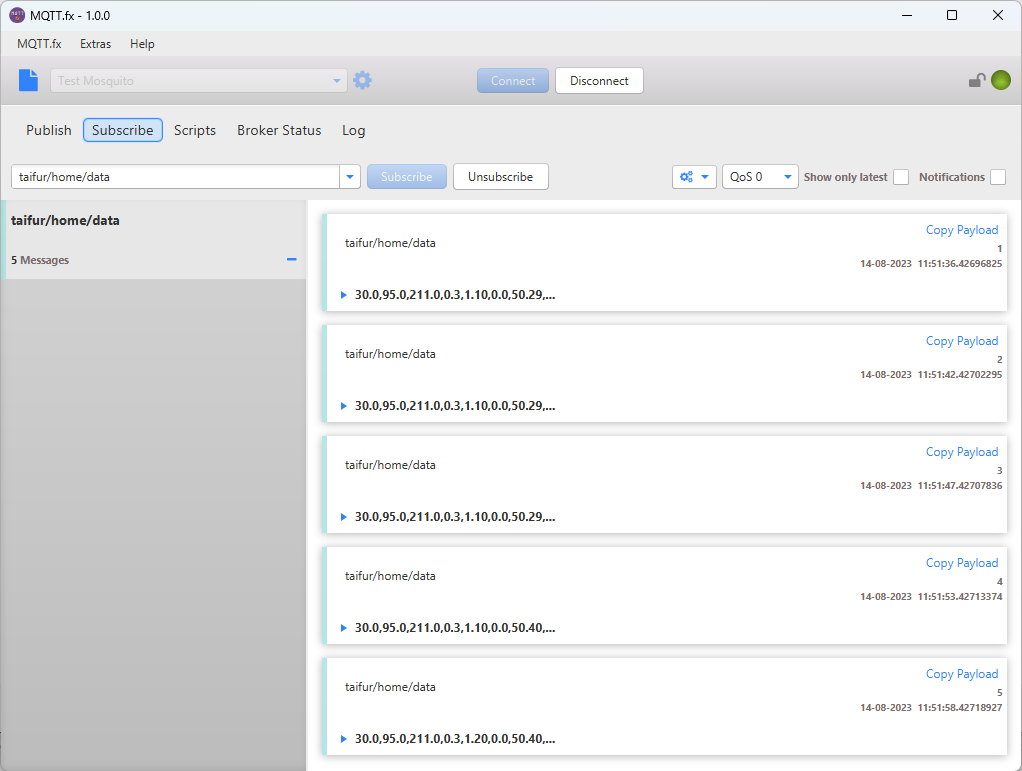
For testing MQTT message is publishing and receiving successfully you can use MQTT.fx tool. Here is the response I got.
Reusing the Code
I have tried to keep the code of one hardware or sensor independent from other hardware. For this reason, I made separate source files for every sensor and hardware. That will help you to easily copy the related source file for a specific sensor or hardware from this project to any other project you like to make using that specific hardware module. The schematic is also very simple and you can easily implement a part of it for other projects.
Step 9: Developing Android App


Android Application Development
I developed an Android application for remote monitoring and control of my home. Through the apps, the status of each appliance with the details power profile can be observed. For developing the Android application I used kodular.io online platform. This is a platform like MIT App Inventor and by using this platform you can develop an Android application with a single line of code. I added the source code for the application in the attachment section. You can modify it by opening it either in kodular.io or appinventor.mit.edu.
The following image shows the development phase of the app in kodular.
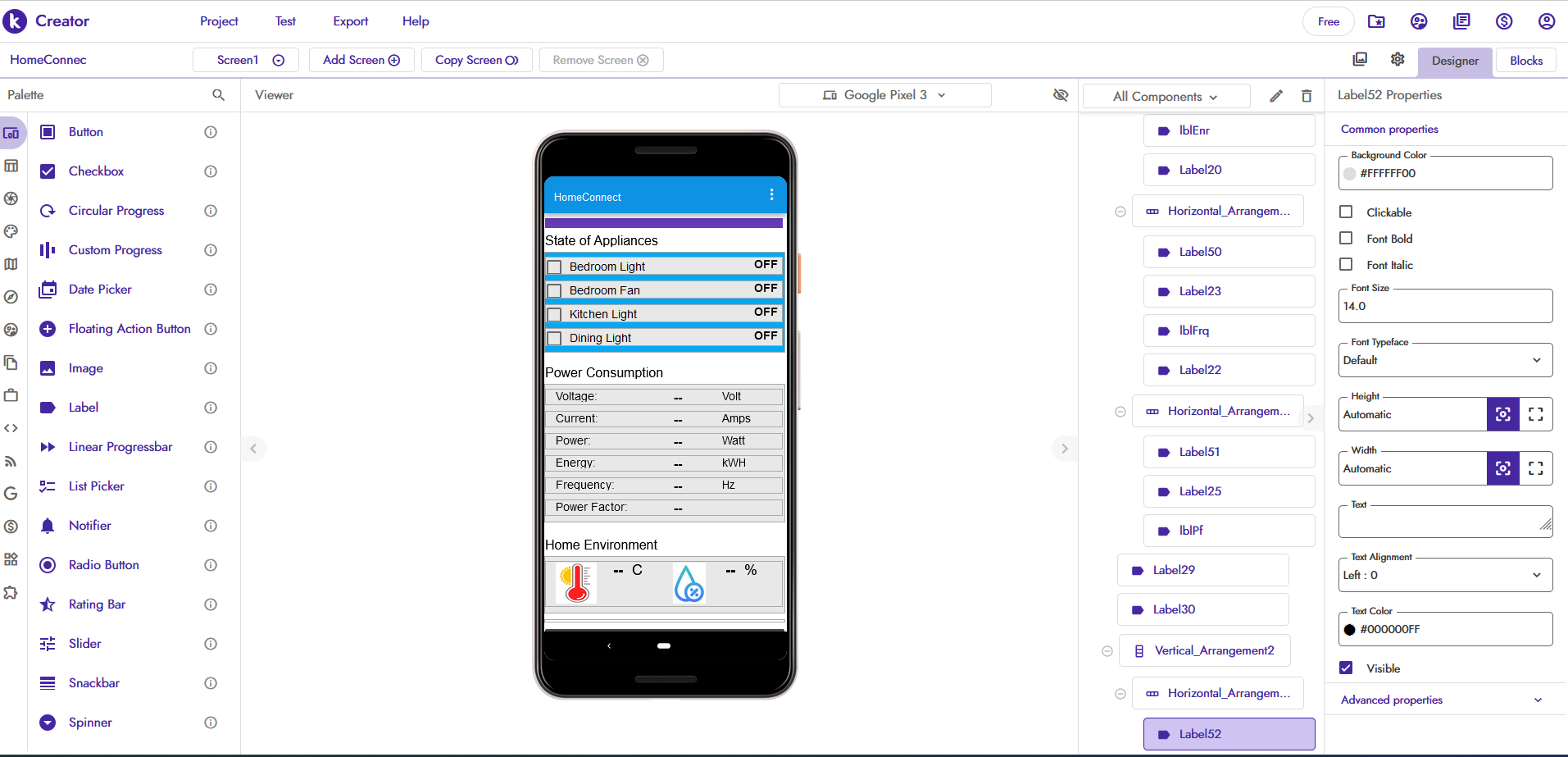
App inventor or kodular uses a graphical user interface (GUI) very similar to the programming languages Scratch and StarLogo, which allows users to drag and drop visual objects (called blocks) to create an application that can be tested on Android and iOS devices. Both of these use a companion mobile app that allows for instant live testing and debugging.
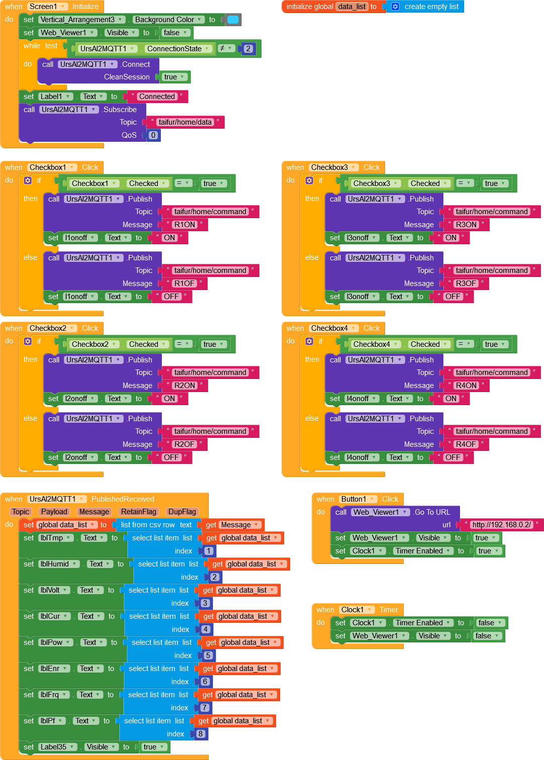
The complete block of my design is given below.
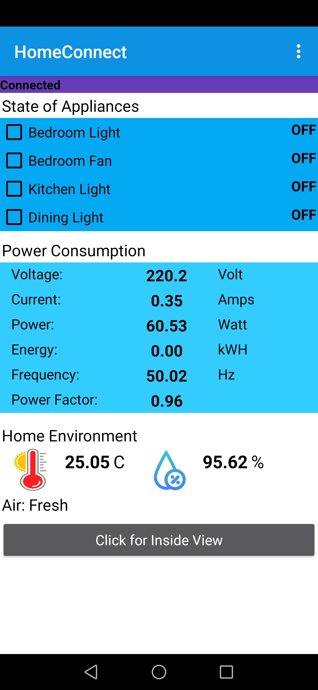
The following image is a screenshot of the application.