

Introduction: Weather Station


In this Instructable I will be showing the steps and the code to build your own weather station! You will be able to cycle through Temperature, Humidity, and Brightness! Please note, your remote Code will be different from mine, but I will show how to find your correct Code IDs!
THINGS YOU NEED:
- 1 x Arduino UNO R3
- 1 x IR Remote (any will do)
- 1 x IR Sensor
- 1 x Photoresistor (Brightness Sensor)
- 1 x 16x2 LCD Screen
- 3 x 220 Ohm Resistor
- 1 x Potentiometer
- 1 x DHT11 (Temp/Humid Sensor)
- 1 x Breadboard
- Jumper Wires
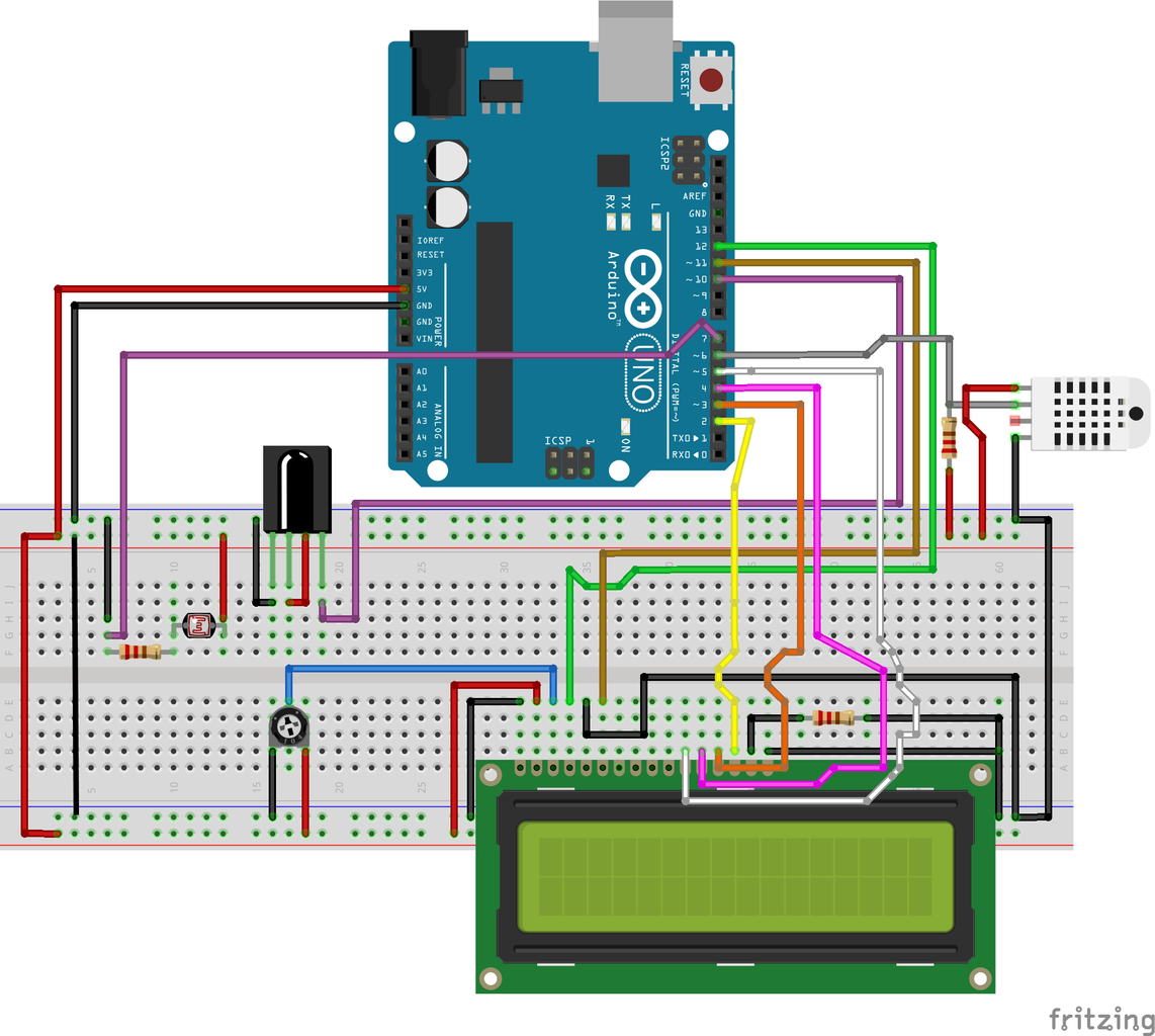
Step 1: Positive and Ground Wires

BASIC SETUP
- Connect 1 jumper wire(red) to the + side of the breadboard to the GND port on the arduino
- Use another jumper wire(red) to connect to the other side of the breadboard on the + rail
- Connect 1 jumper wire(black) to the - side of the breadboard to the 5v port on the arduino
- Use another jumper wire(black) to connect to the other side of the breadboard on the + rail
Step 2: Adding Photoresistor
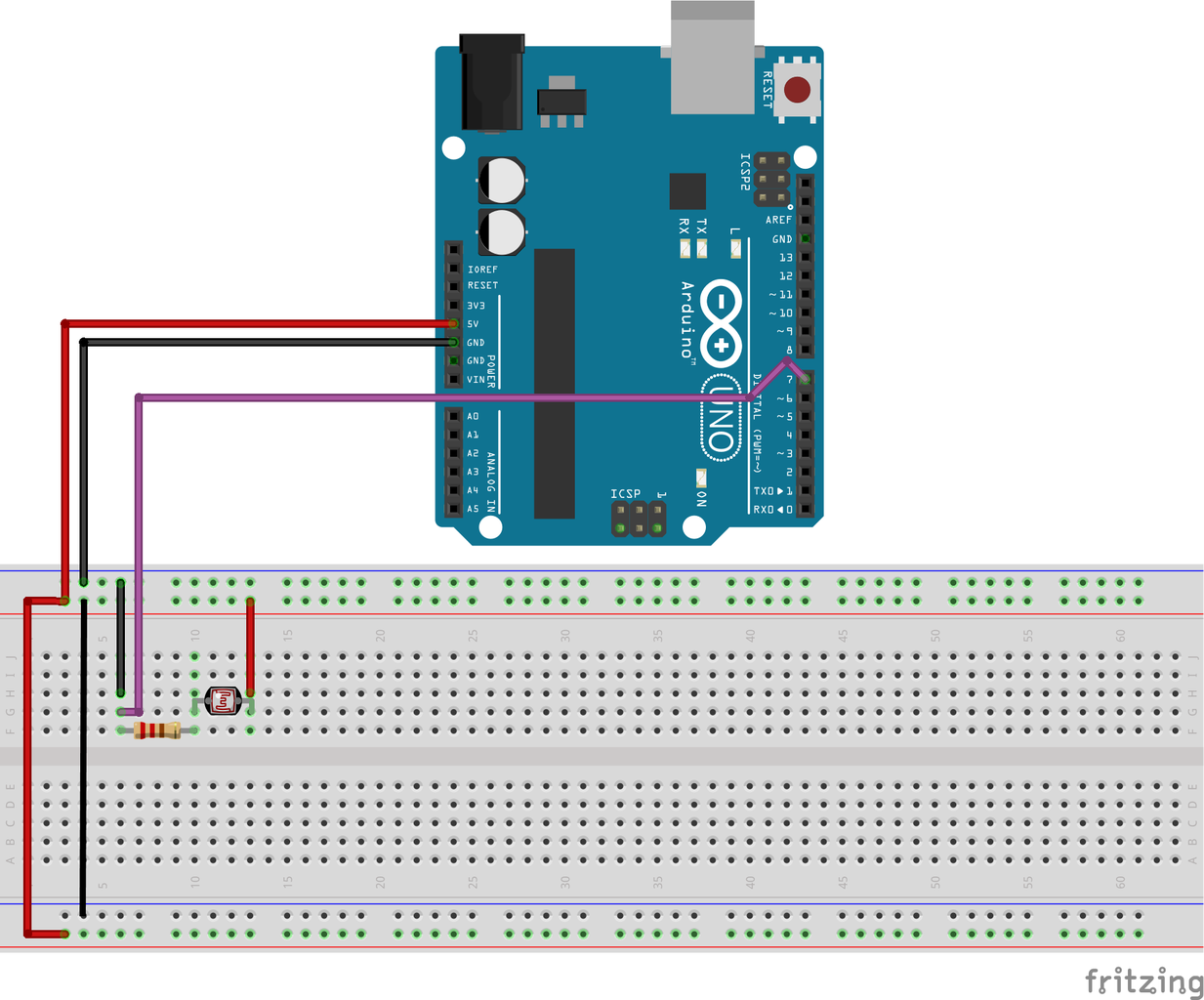
- Place the photoresistor on the breadboard
- Connect the right side to the + rail
- Connect the left side to a 220 Ohm resistor
- Connect a wire from the resistor to port 7 on the arduino
- Connect a ground wire coming from the - rail on the breadboard to the same rail connected to the previous wire(port 7)
Step 3: Add IR Sensor

- Place IR Sensor on breadboard
- Connect the first wire to the GND(-) rail to the first port on the IR
- Connect the second wire to the POSITIVE(+) rail to the second port on the IR
- Connect a wire from port 10 on the arduino to the last post on the IR sensor
Step 4: Adding LCD and Potentiometer

Let's start off with adding the Potentiometer
- Place the LCD Screen and the Potentiometer on the breadboard
- Connect GND(-) rail to the negative side of the potentiometer
- Connect POSITIVE(+) rail to the positive side of the potentiometer
- Connect a wire from the top of the potentiometer to V0 port on the LCD
- This will set the contrast to the LCD to adjust for easier viewing
Let's add the LCD Screen, wires will be in order
- Place the LCD Screen on the breadboard
- Connect a ground wire to the VSS port on the LCD
- (V0 is already connected from the previous step)
- RS will connect to port 12 on arduino
- RW will connect to ground on breadboard
- E will connect to port ~11 on arduino
- D4 will connect to port ~5 on arduino
- D5 will connect to port 4 on arduino
- D6 will connect to port 3 on arduino
- D7 will connect to port 2 on ardiino
- A will connect to a 220 Ohm resistor, the resistor connects to the ground rail on breadboard
- K will connect to connect to the ground rail on breadboard
Step 5: Adding DHT11 (Temperature and Humidity Sensor)

- Place DHT11 on breadboard
- Connect positive rail (+) on breadboard to the positive pin on DHT11, it will be the first pin on the left
- Connect the second pin on the DHT11 to a 220 Ohm resistor
- Connect the 220 Ohm Resistor to port ~6 on arduino
- Connect last and most right pin to the negative rail on breadboard
Step 6: Adding the Remote, Now You're a Weather Man!

If any issues arise while constructing this, please look back through the diagrams are wired correctly. More than likely the remote I used on this, will not be the same as yours. This means you will have to change the code to make it work for you.
- Download the Arduino IDE to make these corrections for your materials.
- Download the code provided (remoteFinder.ino) , open the IDE and upload/compile the program.
- Be sure to open serial monitor.
- Press the two button you would like to use and record the code that the serial monitor gives you.
If you cannot download the file, here it is to copy and paste.
int RECV_PIN = 6;
IRrecv irrecv(RECV_PIN);
decode_results results;
void setup() {
Serial.begin(9600);
irrecv.enableIRIn(); // Start the receiver
}
void loop() {
if (irrecv.decode(&results))
{
Serial.println(results.value, HEX);
irrecv.resume(); // Receive the next value
}
}
Next open up the WeatherStation.ino and change the values for the buttons to yours. In the code they are at the start of the file and are called code1 code2 code3
Compile the code and upload and now you're ready to take over Channel 10!
Attachments

Step 7: Libraries Used
dht.h https://playground.arduino.cc/Main/DHTLib
IRremote.h https://www.arduinolibraries.info/libraries/i-rrem...
LiquidCrystal.h https://www.arduino.cc/en/Reference/LiquidCrystal
If these libraries have updated or they are not working with it feel free to email me and I will send you my libraries!


