

Introduction: Wireless Audio Streaming and Speech Recognition With Arduino


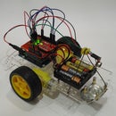

In this project I connect my Arduino Board to a WiFly module (https://www.sparkfun.com/products/10822) from Roving Networks and stream audio to the PC, so that BitVoicer (http://www.bitsophia.com/BitVoicer.aspx) can perform speech recognition. By using a wireless module, I managed to add speech recognition features to my microcontroller without the need of a physical connection with the PC.
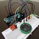
The LEDs do the same basic things they did in my last project (https://www.instructables.com/id/Speech-Recognition-with-Arduino/), but now I eliminated the PC wire connection, so I can finally have a speech activated Arduino anywhere my wireless network reaches.
Here is the YouTube video of the project:
I used a WiFly module from Roving Networks (https://www.sparkfun.com/products/10822) because I read somewhere that it would work with the XBee Shield I had (https://www.sparkfun.com/products/9976). Unfortunately, I found out the hard way that a diode between the Arduino TX and the WiFly RX was blocking the signal. I had to rip out the diode and add a voltage divider between the TX/RX pins of the Arduino and the WiFly module because the RX pin of the WiFly is 3.3V tolerant and the Arduino TX works at 5V. It does not seem to be the best approach, but it worked and I was able to send and receive data from the module. I found out that Sparkfun released a new version of the XBee Shield (https://www.sparkfun.com/products/10854) and that the diode level shifter was replaced with a more robust MOSFET level shifter. This should solve the diode problem.
I believe any of the following wireless modules could be used. You just have to find out which one of them best fits your needs:
- http://arduino.cc/en/Main/ArduinoWiFiShield
- http://www.rovingnetworks.com/products/RN171XV
- https://www.sparkfun.com/pages/xbee_guide (you will need a XBee Explorer Dongle to connect the XBee to your computer: https://www.sparkfun.com/products/9819)
- Many other Arduino WiFi Shields can be found here: http://postscapes.com/arduino-wifi
The setup process of the WiFly module can be tricky, so I’m also adding a step-by-step tutorial on how to do it. In my case, I use a regular access point/router from D-Link to implement my private wireless network. This tutorial should work with any access point out there.
1. Disconnect your computer from any wireless network
2. Set the GPIO9 pin of the WiFly module to high (3.3V) at power up. This enables adhoc mode on the module. I used the 3.3V source from the Arduino board and an ordinary jumper wire. Right after the power up, remove the wire and follow the next steps. Module datasheet: http://dlnmh9ip6v2uc.cloudfront.net/datasheets/Wireless/WiFi/WiFly-RN-XV-DS.pdf
3. On your computer, search for available networks and connect to the WiFly module network (WiFly-GSX-XX). It may take a few seconds before your computer gets an IP address from the module.
4. Download and run a free software called TeraTerm (http://www.rovingnetworks.com/resources/download/86/Teraterm)
5. Enter the following settings and click on OK: IP Address: 169.254.1.1; TCP port: 2000; Service: Telnet; Protocol: IPv4
6. You should see the word “*HELLO*” on the screen.
7. Type $$$ to enter command mode
8. Type scan and hit enter to scan for available access points
9. If your network uses WPA authentication, use the command set wlan phrase to set the pass phrase. For WEP, set the key using the set wlan key command. My network is WEP secured, so I had to use the second command. The problem is that the key must be entered ASCII/HEX encoded and it MUST have exactly 26 characters. I found this page that converts text to ASCII/HEX: http://www.string-functions.com/string-hex.aspx.
10. Type set wlan ssid , where XXXX is the SSID of you network (look at the results of step 8)
11. Type save
12. Type join (look at the results of step 8)
13. The WiFly-GSX-XX will disappear from the windows network list
14. Close Teraterm
15. Reconnect your computer to your local wireless network
16. Turn your Arduino board OFF and back ON
17. Write down the IP number assigned to the WiFly module by your access point (usually, you can find this info on the access point DHCP page)
18. Open Teratem using the new IP address and the other settings from step 5
19. Type $$$ to enter command mode
20. Type set comm close 0 and hit enter
21. Type set comm open 0 and hit enter
22. Type set comm remote 0 and hit enter
23. Type set comm size 1460 and hit enter
24. Type set comm time 1000 and hit enter
25. Type set comm baud 115200 and hit enter (the same baud rate I used in my sketch)
26. Type save and hit enter
27. Type exit and hit enter
28. Close Teraterm
Now your WiFly module should be able to communicate with BitVoicer and your PC. The WiFly user’s manual can be downloaded here: http://dlnmh9ip6v2uc.cloudfront.net/datasheets/Wireless/WiFi/WiFly-RN-UM.pdf
This is the sketch I used to control the LEDs, capture audio and interact with BitVoicer:
#include <BitVoicer11.h>
//Instantiates the BitVoicerSerial class
BitVoicerSerial bvSerial = BitVoicerSerial();
//Stores true if the Audio Streaming Calibration tool
//is running
boolean sampleTest = false;
//Stores the data type retrieved by getData()
byte dataType = 0;
//Sets up the pins and default variables
int pinR = 3;
int pinY = 5;
int pinG = 6;
int lightLevel = 0;
void setup()
{
//Sets the analog reference to external (AREF pin)
//WARNING!!! If anything is conected to the AREF pin,
//this function MUST be called first. Otherwise, it will
//damage the board.
bvSerial.setAnalogReference(BV_EXTERNAL);
//Sets up the microcontroller to perform faster analog reads
//on the specified pin
bvSerial.setAudioInput(0);
//Starts serial communication at 115200 bps
Serial.begin(115200);
//Sets up the pinModes
pinMode(pinR, OUTPUT);
pinMode(pinY, OUTPUT);
pinMode(pinG, OUTPUT);
}
void loop()
{
//Captures audio and sends it to BitVoicer if the Audio
//Streaming Calibration Tool is running
if (sampleTest == true)
{
//The value passed to the function is the time
//(in microseconds) that the function has to wait before
//performing the reading. It is used to achieve about
//8000 readings per second.
bvSerial.processAudio(46);
}
//Captures audio and sends it to BitVoicer if the Speech
//Recognition Engine is running
if (bvSerial.engineRunning)
{
//The value passed to the function is the time
//(in microseconds) that the function has to wait before
//performing the reading. It is used to achieve about
//8000 readings per second.
bvSerial.processAudio(46);
}
}
//This function runs every time serial data is available
//in the serial buffer after a loop
void serialEvent()
{
//Reads the serial buffer and stores the received data type
dataType = bvSerial.getData();
//Changes the value of sampleTest if the received data was
//the start/stop sampling command
if (dataType == BV_COMMAND)
sampleTest = bvSerial.cmdData;
//Signals BitVoicer's Speech Recognition Engine to start
//listening to audio streams after the engineRunning status
//was received
if (dataType == BV_STATUS && bvSerial.engineRunning == true)
bvSerial.startStopListening();
//Checks if the data type is the same as the one in the
//Voice Schema
if (dataType == BV_STR)
setLEDs();
}
//Performs the LED changes according to the value in
//bvSerial.strData
void setLEDs()
{
if (bvSerial.strData == "wake")
{
digitalWrite(pinR, LOW);
digitalWrite(pinY, LOW);
digitalWrite(pinG, LOW);
digitalWrite(pinR, HIGH);
digitalWrite(pinY, HIGH);
digitalWrite(pinG, HIGH);
delay(200);
digitalWrite(pinR, LOW);
digitalWrite(pinY, LOW);
digitalWrite(pinG, LOW);
delay(200);
digitalWrite(pinR, HIGH);
digitalWrite(pinY, HIGH);
digitalWrite(pinG, HIGH);
delay(200);
digitalWrite(pinR, LOW);
digitalWrite(pinY, LOW);
digitalWrite(pinG, LOW);
delay(200);
digitalWrite(pinR, HIGH);
digitalWrite(pinY, HIGH);
digitalWrite(pinG, HIGH);
delay(200);
digitalWrite(pinR, LOW);
digitalWrite(pinY, LOW);
digitalWrite(pinG, LOW);
lightLevel = 0;
}
else if (bvSerial.strData == "sleep")
{
digitalWrite(pinR, LOW);
digitalWrite(pinY, LOW);
digitalWrite(pinG, LOW);
digitalWrite(pinR, HIGH);
digitalWrite(pinY, HIGH);
digitalWrite(pinG, HIGH);
delay(200);
digitalWrite(pinR, LOW);
digitalWrite(pinY, LOW);
digitalWrite(pinG, LOW);
delay(200);
digitalWrite(pinR, HIGH);
digitalWrite(pinY, HIGH);
digitalWrite(pinG, HIGH);
delay(200);
digitalWrite(pinR, LOW);
digitalWrite(pinY, LOW);
digitalWrite(pinG, LOW);
lightLevel = 0;
}
else if (bvSerial.strData == "RH")
{
digitalWrite(pinR, HIGH);
lightLevel = 255;
}
else if (bvSerial.strData == "RL")
{
digitalWrite(pinR, LOW);
lightLevel = 0;
}
else if (bvSerial.strData == "YH")
{
digitalWrite(pinY, HIGH);
lightLevel = 255;
}
else if (bvSerial.strData == "YL")
{
digitalWrite(pinY, LOW);
lightLevel = 0;
}
else if (bvSerial.strData == "GH")
{
digitalWrite(pinG, HIGH);
lightLevel = 255;
}
else if (bvSerial.strData == "GL")
{
digitalWrite(pinG, LOW);
lightLevel = 0;
}
else if (bvSerial.strData == "ALLON")
{
digitalWrite(pinR, HIGH);
digitalWrite(pinY, HIGH);
digitalWrite(pinG, HIGH);
lightLevel = 255;
}
else if (bvSerial.strData == "ALLOFF")
{
digitalWrite(pinR, LOW);
digitalWrite(pinY, LOW);
digitalWrite(pinG, LOW);
lightLevel = 0;
}
else if (bvSerial.strData == "brighter")
{
if (lightLevel < 255)
{
lightLevel += 85;
analogWrite(pinR, lightLevel);
analogWrite(pinY, lightLevel);
analogWrite(pinG, lightLevel);
}
}
else if (bvSerial.strData == "darker")
{
if (lightLevel > 0)
{
lightLevel -= 85;
analogWrite(pinR, lightLevel);
analogWrite(pinY, lightLevel);
analogWrite(pinG, lightLevel);
}
}
else
{
bvSerial.startStopListening();
bvSerial.sendToBV("ERROR:" + bvSerial.strData);
bvSerial.startStopListening();
}
}
The BitVocier Voice Schema I used can be downloaded here: http://www.justbuss.xpg.com.br/BitVoicerTest3.zip
If you have any question about this project, please post it here, so anyone else can read the answer.


