

Introduction: Introduction


In this era of Bluetooth, WiFi and IoT we are somewhere forgetting the old Radio frequency modulations used to transmit data wireless. Here I'm presenting a very simple wireless data link between a computer/laptop and an Arduino uno which can display the data sent from the computer terminal wirelessly on a 16x2 LCD.
This project can be used as a wireless message display board, the display can easily be changed to a dot matrix display or a larger LCD like 20x4. You can send text data over the wireless link which uses the ISM band frequency of 433MHz which is free and unlicensed.
This project can also used with multiple displays. A single transmitter sending data on a frequency of 433MHz and multiple receviers with LCDs can be used to display the same message on all the LCDs.
It can be used to digital advertising purpose or for displaying other notices/messages.
Step 1: Wireless Notice Board System Using Arduino

Here in this Instrcutable I'm presenting a simple Wireless notice board system made using two Arduinos and 434 MHz ASK RF Modules.
This system can be used in schools and colleges to flash a notice or message on a LCD. Multiple receivers can be used to receive the same message across the whole college campus.
The message to be displayed is given to the transmitting arduino from PC/Laptop via the serial monitor in Arduino IDE.
Let's get started!!
Step 2: Parts Required
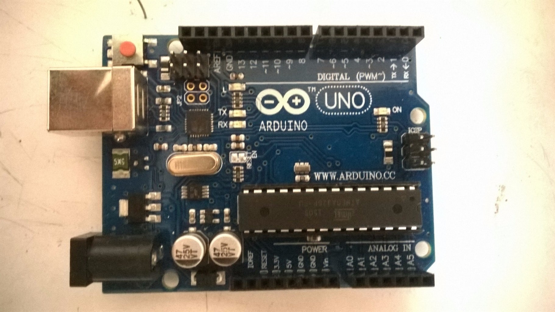


1.Two Arduino boards(I'm using an Arduino Uno and one Arduino Mini)
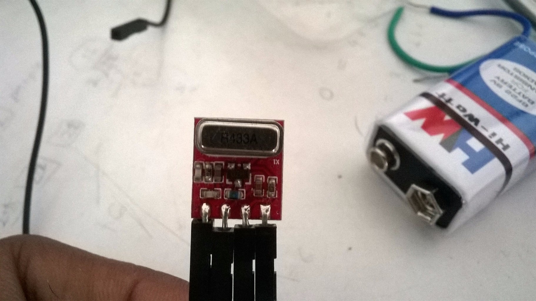
2.434 MHz ASK RF module pair
3.16 x 2 LCD
4.Connecting wires
5.10 k potentiometer
Step 3: Connection Diagram
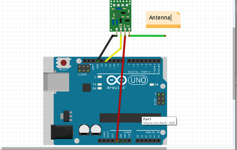

Here's a brief about connection diagram.
First Arduino Uno is used as the transmitter. The data pin of 434 MHz Tx is connected to pin 12 of Arduino Uno.
The Tx module has 4 pins. Vcc goes to +5V,Gnd goes to Gnd, Ant is the antenna connect a small wire 10-12cm and data pin to pin 12 of Arduino.
The Rx module is connected to Arduino Mini. It also has 4 pins(some modules have 2 data and 3 gnd pins) Ignore them. The data pin is connected to pin D11 of Mini. Vcc and Gnd are connected to +5V and gnd respectively.Antenna is a long wire 10-12cm.
Step 4: Code
The code uses VirtualWire library for transmitting and receiver wireless data.
Transmitter.ino contains the code for transmitter arduino.
receiver.ino contains the code for receiver arduino.
Here's the library download and install it.

Step 5: Testing the System
Here's a Video showing the system in action.
Hope you liked my instructable.
Attachments


Participated in the
Arduino All The Things! Contest

![Tim's Mechanical Spider Leg [LU9685-20CU]](https://content.instructables.com/FFB/5R4I/LVKZ6G6R/FFB5R4ILVKZ6G6R.png?auto=webp&crop=1.2%3A1&frame=1&width=306)


