

Introduction: 120V A/C Lamp Flicker From LED Votive Candle Type 1 (COB)


Need some flickering lights to make your Halloween Haunt complete? Frustrated by other solutions? Like to melt solder and re-purpose electronics? Then this Instructable is right up your alley.
This Instructable addresses only the actual flicker electronics. Integration into lanterns, pumpkins, candles, etc. is an exercise left to the reader. Personally, I'm using this circuit in two lanterns, a molded plastic pumpkin and for a string of pumpkin lights.
Note: There are at least two types of LED votives. This instructable will deal only with what I call type 1 devices - so-called because these were the first type I found. Type 1 LED votives have a small circuit board in them with a chip-on-board (COB) circuit and an LED. Type 2 LED votives have the circuit embedded in the LED itself, similar to a standard flashing LED. I have not yet determined a usable configuration for this type. For this instructable, you will need the type 1 COB LED votives. Unfortunately I think the only way you can determine what you have is to open them up.
Disclaimer: This circuit uses 120V A/C house current. It is quite capable of killing you if you are careless. All devices using this circuit should be housed in an insulated container (e.g. plastic). This is not recommended as a beginning electronics project. The poster disavows any responsibility for damages, injuries or death sustained as a result of constructing or using this circuit.
Hey, we all know anything really fun can kill you ;-)
Another note: This instructable is somewhat of a skeleton (hey, it IS Halloween). The author expects anyone knowledgeable enough to construct this can figure out how to put it together on something other than a breadboard.
This circuit is NOT approved by Underwriters Laboratories!
Step 1: Parts List

Of course you'll need some parts:
- 1 LED votive candle
- 1 extension cord (to provide power to circuit)
- 1 lamp and socket that you want to "flicker"
- 1 full wave bridge rectifier -or-
- 4 200v or better rectifier diodes to construct bridge rectifier
- 1 470nF 250v capacitor or similar/better
- 1 3.1v zener diode
- 1 470uF 10v electrolytic capacitor or similar/better
- 1 220 ohm resistor
- 1 MOC3023 opto-isolator/triac driver
- 1 BT134 (or simiar) triac
I salvaged the 470nF 250v capacitors and full wave bridge rectifier from a CRT monitor.
I used the extension cord to provide a power cord for the circuit, cutting off the triple tap end. I've also used the triple tap connected as the "load" for the circuit so I can plug in a string of novelty lights.
Note: If you try to drive a large load with this circuit, the triac will heat up significantly and require a heat sink.
You'll also need perfboard, soldering iron, wire, strippers, etc.
Step 2: Schematic

A few notes:
Again, this circuit is powered by 120V A/C house current. You can be injured or killed if you are careless or make a mistake.
Components C1, B1, D1 and C2 make a transformer-less low voltage supply for the chip on board flasher removed from the LED votive. I don't pretend to understand this section completely, but my general level of understanding is: C1 limits the current from the 120V house supply. B1 is a full wave bridge rectifier, either a single device or constructed from 4 rectifier diodes. The output is DC. D1 is a 3.1V zener diode which limits the voltage. Need a higher voltage, us a different value zener diode. C2 is a polarized electrolytic capacitor and smooths the ripple from the DC. The resulting DC is "good enough" for the COB.
The MOC3023 opto-isolator triac driver contains an internal IR LED. This LED takes the place of the LED originally driven by the COB.
When the voltage output from the COB is high enough, the IR LED in the MOC3023 turns on which excites the "IR sensitive diac" (my terminology) which in turn turns on the triac and supplies power to the load - which could be a hardwired lamp as in a lantern.
The load MUST be an incandescent lamp! Do not attempt to drive compact fluorescent lamps, motors, bug zappers or anything else.
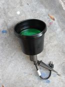
Step 3: Harvest the COB From the LED Votive

Crack open the LED votive however you like. Usually the bottom will pry out/off. Hopefully you'll see something similar to the picture below. The circuit board with the LED is what you want. Note all polarities.
Unsolder the LED. Solder in pins made from old component leads if you want. This makes it easier to mount on a breadboard or perfboard.
If you don't see a circuit board like this, but only an LED connected to the battery and switch, then you have a Type 2 LED votive. Sorry but you're on your own or wait and see if I figure out a useful circuit in time for your needs.
Step 4: Breadboarded Circuit

Here is the circuit on a breadboard. Refer to the image for more information.
Step 5: Action
Step 6: Your Turn
OK, now you've got the basic circuit. It's up you to deploy it in a safe case and put it to use. I've used it in lanterns and pumpkins. I've even used one of those triple taps that I cut off of the extension cord to be able to use the circuit to easily drive a string of novelty lights.
Remember if you load up the circuit too much, you'll need to heatsink the triac.
Have fun and be creative!
Step 7: Addendum
I had a small piezo speaker, so I plugged the leads into the output of the COB/input of the opto-isolator. Sure enough, the COB was playing Fur Elise. Listen carefully to the video and you can hear the music.
I had a couple of other LED votives kicking around so I checked them. One played "Happy Birthday" and was a poor choice for this circuit. Another one did not actually play music, but made "duh duh duh" sounds in a pattern. That one worked OK in this circuit too.
It may be possible to tweak the circuit some to give you a more pleasing result. Adding resistors and/or capacitors to the output of the COB/input of the opto-isolator can influence the results. It may also be possible to influence the results by changing the value of the 220 ohm resistor on the 'output' side of opto-isolator. If you find a particularly good combination, please let everyone know.
You can also use a SCR in place of the triac. This will reduce power to the load by 50% since it is a half-wave device. You'll probably have to switch the leads/pins around as it's unlikely the SCR will have the same pin configuration as the triac.
Have fun and be safe. Once again, this circuit has lethal potential!


