

Introduction: A 3D Printed Quadruped Robot
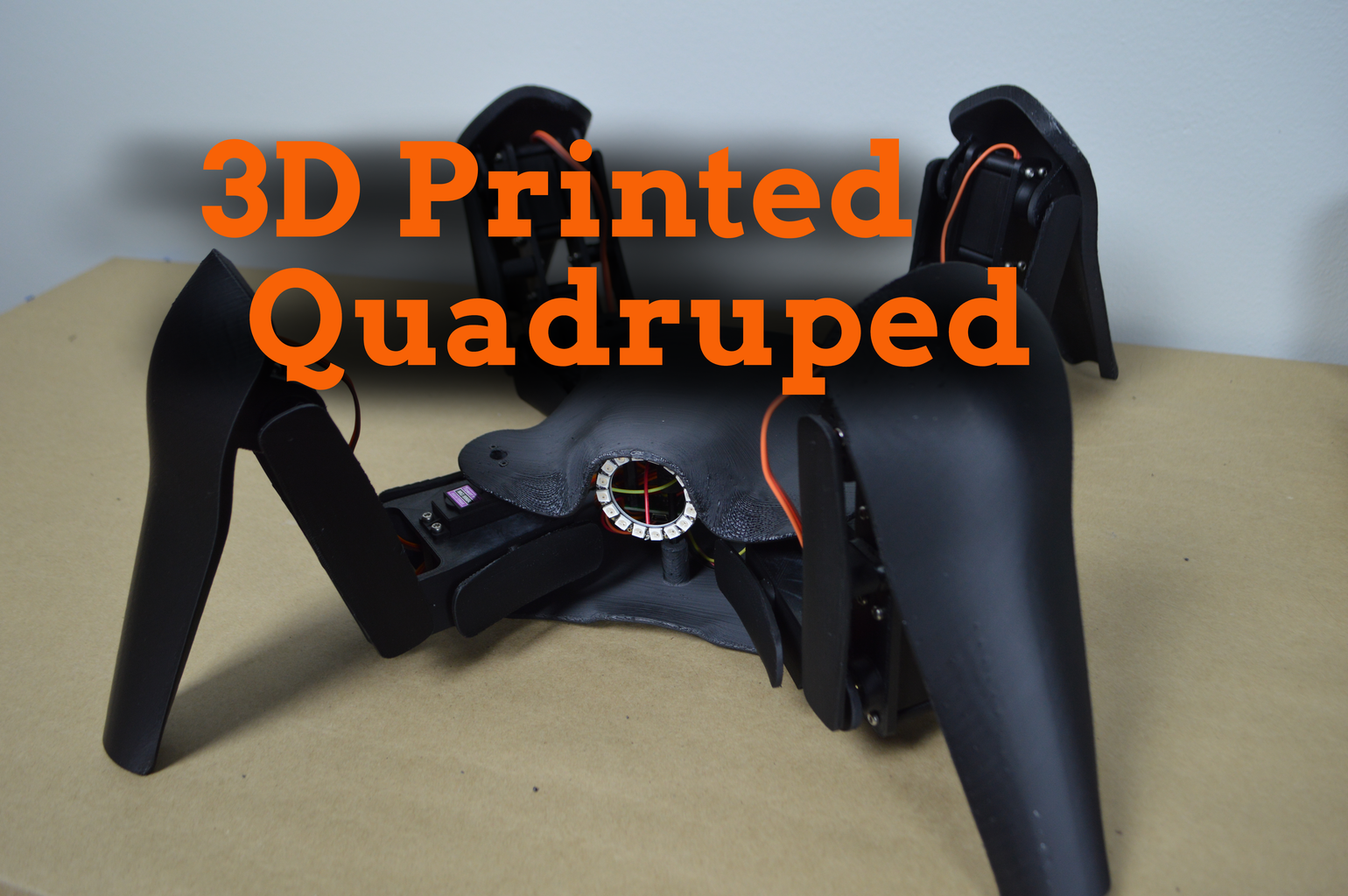


This Instructable will show you how to build a quadruped robot from scratch using 3D printed parts and off-the-shelf electronic components.
Robot Design
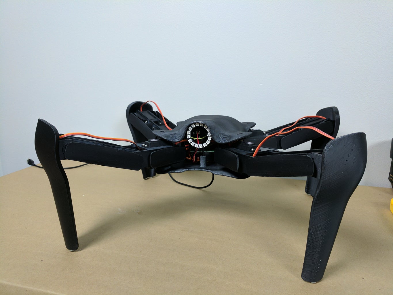
A quadruped robot is a robot with four legs. There are any number of ways a four-legged robot can be designed. The robot we will be building in this Instructable has four legs arranged symmetrically around the body.
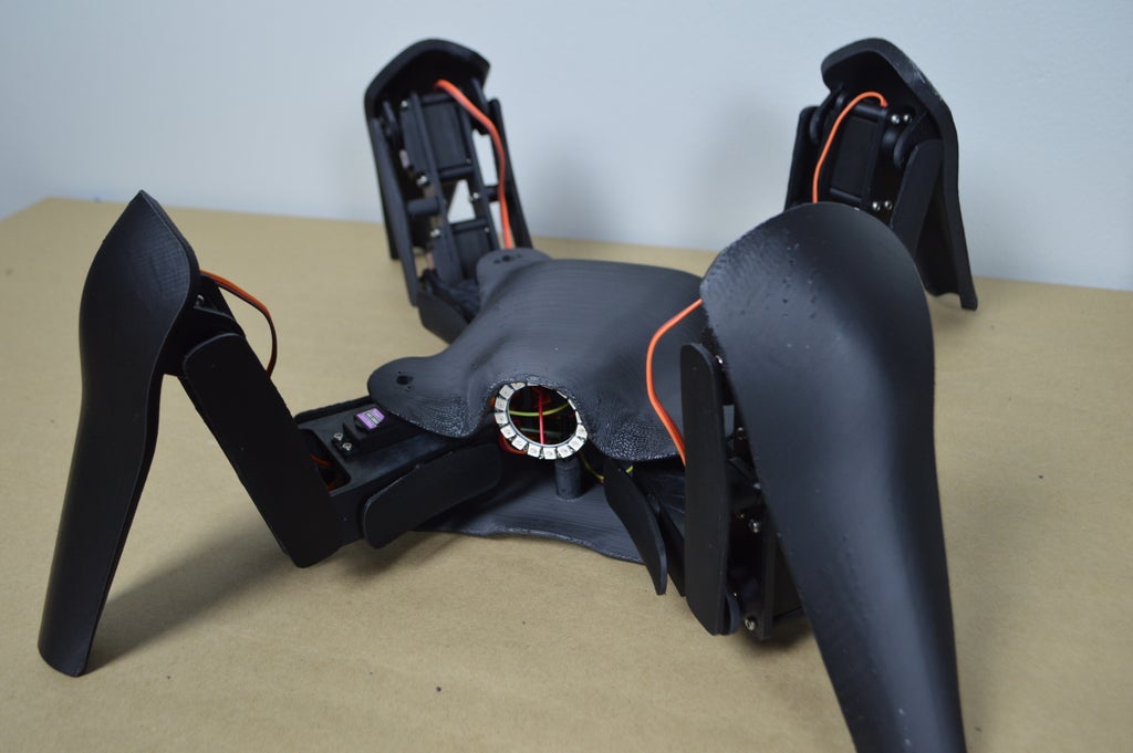
Each leg is actuated by three servos: one for forward/backward movement, one for up/down movement, and one to bend the leg in the middle. This gives the robot three degrees of freedom, allowing it to move in any direction.

The robot is also equipped with a NeoPixel LED ring that functions as the robot's eye. This part is used mostly for aesthetics, however it is also useful for making it easier to identify the front side of the robot since it is symmetrical. Giving the robot a kind of "face" also gives it some anthropomorphism.

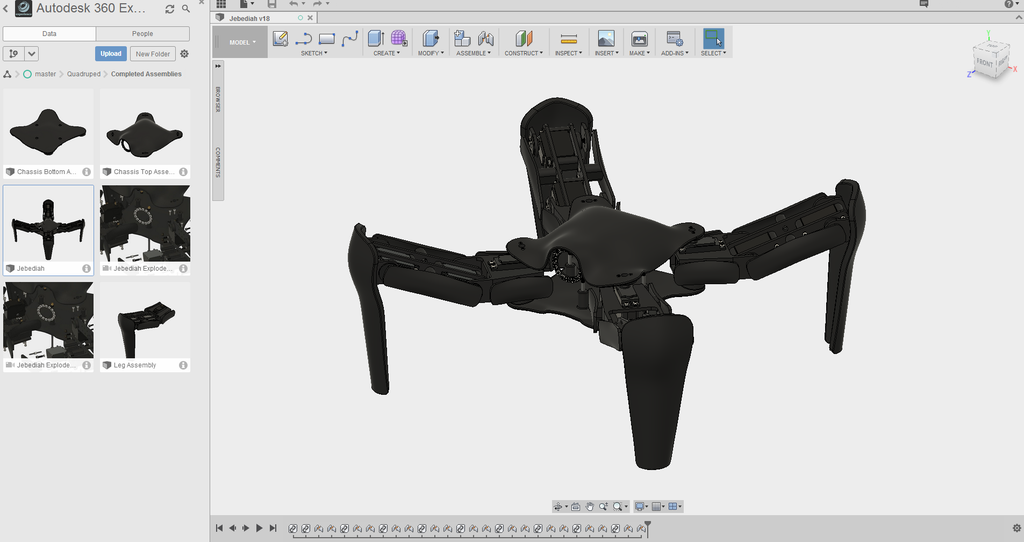
All of the design work for the quadruped was done in Autodesk Fusion 360.
Motion
Since the quadruped can articulate each of its four legs with three degrees of freedom, it has a highly flexible range of motion.

Robot Construction
The quadruped is constructed mostly from 3D printed frame parts and readily available hardware. The electronics used to power and control the robot are normal (albeit high quality) hobby servos and Arduino-compatible microcontrollers.
Robot Control
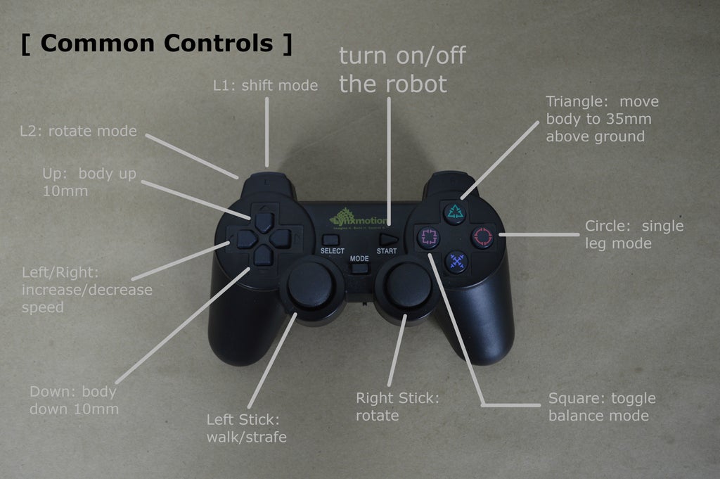
The robot is controlled with a wireless third-party Playstation 2 controller.
Step 1: Gather Your Parts
We will need the parts below to complete the build, along with some general-purpose materials like solder and hot glue.
Electronics Parts
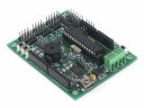 Lynxmotion Botboarduino Quantity: 1 |  SSC-32 Servo Controller Quantity: 1 | 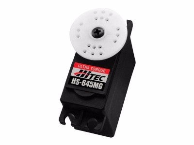 Hitec HS-645MG Servo Quantity: 12 |
 Wireless PS2 Controller Quantity: 1 |  16 LED NeoPixel Ring Quantity: 1 |  5V 10A Power Supply Quantity: 1 |
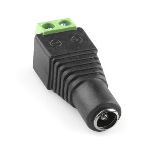 Barrel Jack Adapter Quantity: 1 |  AA Batteries Quantity: 2 | 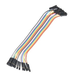 F/F Jumper Wires Quantity: 20 (1 pack) |
Mechanical Parts
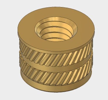 M3 Heat-Set Inserts Quantity: 36 | 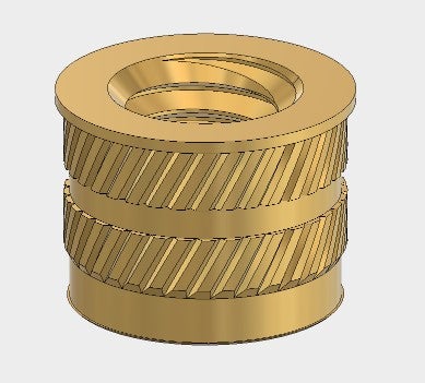 M4 Heat-Set Inserts Quantity: 12 |  M3 Self-Tapping Screws Quantity: 96 |
 M3 x 10mm Screw Quantity: 32 | M2 x 8mm Screw Quantity: 24 |  M4 x 12mm Screw Quantity: 8 |
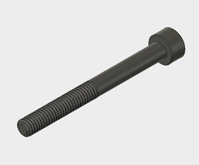 M3 x 50mm Screw Quantity: 4 |  6 x 13mm Ball Bearing Quantity: 4 | 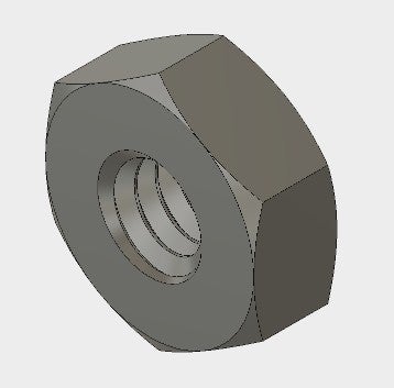 M2 Nut Quantity: 8 |
Step 2: 3D Print the Frame


The frame for the quadruped robot uses a total of 38 3D printed parts. All of the files for printing these parts can be found in the GitHub repository I created for this project.
| Part | Quantity | Image |
|---|---|---|
| Chassis Top | 1 |  |
| Chassis Bottom | 1 |  |
| Coxa Top | 4 |  |
| Coxa Bottom | 4 |  |
| Femur Frontplate | 4 |  |
| Femur Backplate | 4 | |
| Tibia | 4 |  |
| Coxa Cover | 8 | 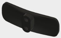 |
| Femur Cover Left | 4 |  |
| Femur Cover Right | 4 | |
Some of the 3D printed parts for this build are quite challenging to print, and some of the parts are very large; you will therefore need a fairly high-end 3D printer to make all the parts. My 3D printer did not have a large enough build platform, so I used 3D Hubs to get my parts made and I had a great experience with the service.
Why a 3D printed frame?
One of the reasons for using 3D printed parts for this quadruped build is that the 3D printed frame is extremely light weight. Keeping the robot's weight low is extremely important. In order to avoid spending a fortune on servos for this project, the TowerPro MG996R servos we will be using

Parts of a Arthropod Robot Leg
Throughout this Instructable, I will be referring to the leg parts and servos according to their position and function on the legs. The quadruped robot uses an arthropod leg design with the parts of the leg named after the leg bones on an animal. Likewise, the servos are named according to the leg segment they actuate.
[leg part label]
Step 3: Install Heat-Set Inserts Into Covers


In order to partially conceal the quadruped's leg mechanisms and improve the aesthetics of the robot, the femurs and coxas have decorative covers. The covers are simple 3D printed plates that mount onto the leg sections. The covers will mount to the corresponding leg assemblies using M3 machine screws. Rather than trying to force the screws to thread into the 3D printed covers, or try to design the covers with a captive nut, we will create metal threads for the covers using heat-set inserts.

Heat-set inserts are simple parts, but they will allow the cover pieces to be attached and detached with ease. To install the heat-set inserts, we will need a soldering iron, a pair of hemostats, and a way to hold the 3D printed covers steady. For this last piece of equipment, I am using a great helping hands tool from QuadHands.
To install the heat set inserts, warm your soldering iron to 230o C. Then, with the 3D printed part clamped in place, hold the heat-set insert with the hemostats just over the hole. Press the heat-set insert into the plastic part with the soldering iron. The heat from the soldering iron should melt the plastic, allowing the heat-set insert to set into the part. Try to work quickly to avoid applying too much heat and deforming the plastic surrounding the holes.
Install heat set inserts into both hols on each of the 16 cover pieces.
Step 4: Install Heat-Set Inserts Into Chassis Top


Next we will install heat-set inserts into the top chasis part the same way we installed the inserts into the cover parts in the previous step. Four M3 heat-set inserts will be used to mount the robot control board to the chassis later on, and four M4 heat-set inserts will be used to connect the top and bottom chassis parts.
Install the heat-set inserts into the top chassis part using the same technique as we used in the previous step. You should be getting fairly good at installing the inserts at this point, having just installed 32 inserts into the cover parts.
Step 5: Install Heat-Set Inserts Into Femur Backplates


By this point you are probably an expert at installing heat-set inserts. Later on, we will be using an M4 machine screw to form the hinges for the femur-tibia joints and the coxa-femur joints. We will install M4 heat-set inserts into the Femur Backplate parts so we can install the machine screws later on. Using the same technique we employed for the cover pieces and the top chassis piece, install the heat-set inserts into the protruding bosses on the Femur Backplates.
Step 6: Remove Horns From Servos


Before continuing the build, we need to take the preparatory step of removing the horns from all the servos. We need to do this for two reasons. First, the servo horns will connect to various other parts using M2 screws. However, the holes in the horns are actually smaller than 2mm. We will therefore need to drill the holes to a slightly larger size.
The second reason we need to remove the servo horns is because they will be installed onto the tibia parts and the coxa parts first, and reconnected to the servos second.
Step 7: Mount Servos to Femur Frontplates


The next step in assembling the quadruped robot is to mount the servos onto the 3D printed Femur Frontplate parts as shown in the animation below. The shafts for the servos (note that the horns are removed at this point) should be closest to the ends of the Femur Frontplate parts.

We will attach the servos to the Femur Frontplate parts using M3 self-tapping screws made specifically for plastics. These screws have especially sharp threads and the threads are very corse. This design means the screws will be able to easily cut threads into the plastic and the screws require very little force to drive in, which means there is little risk of breaking the 3D printed parts by attaching other components using these screws.
Step 8: Attach Backplate to Femur Frontplates


With the servos attached to the Femur Frontplate, we will complete the femur assembly by attaching the Femur Backplate part. The Femur Backplate connects to the Femur Frontplate with eight M3 self-tapping screws. The two holes in the center of the Femur Backplate parts will be left open for connecting the cover pieces later on.

Step 9: Drill Out Servo Horn Holes


In the next few steps we will be mounting the servo horns onto the tibia and coxa parts. We will fasten the servo horns onto the 3D printed parts with M2 screws. However, the holes in the servo horns are actually smaller than 2mm. Therefore, we will drill out the holes to expand them to 2mm so the screws will fit.
Using a 2mm drill bit, carefully drill out two diametrically opposed holes on each of the 12 servo horns.
Step 10: Center the Servos

The only feedback mechanism available for the quadruped robot to figure out its posture is the positional feedback of the servos. In other words, the robot's controller only knows the angle of each servo. From this information alone, the firmware must be able to determine the position of each leg. It is extremely important that, when the servos are at their center position, the coxa and femur are co-linear, and that the tibia and femur are perpendicular, as shown in the rendering below.

We will go into more detail about building the quadruped's legs later in this Instructable. For now, we just need to make sure each servo is at its midpoint before assembling the robot.
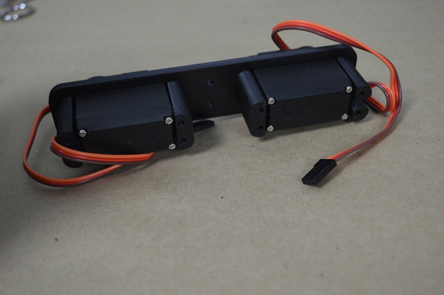
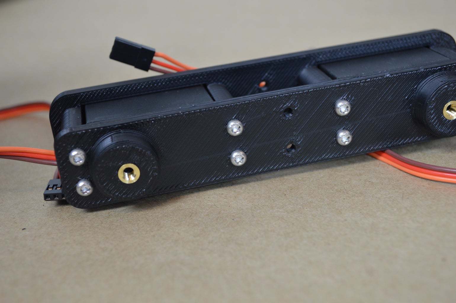
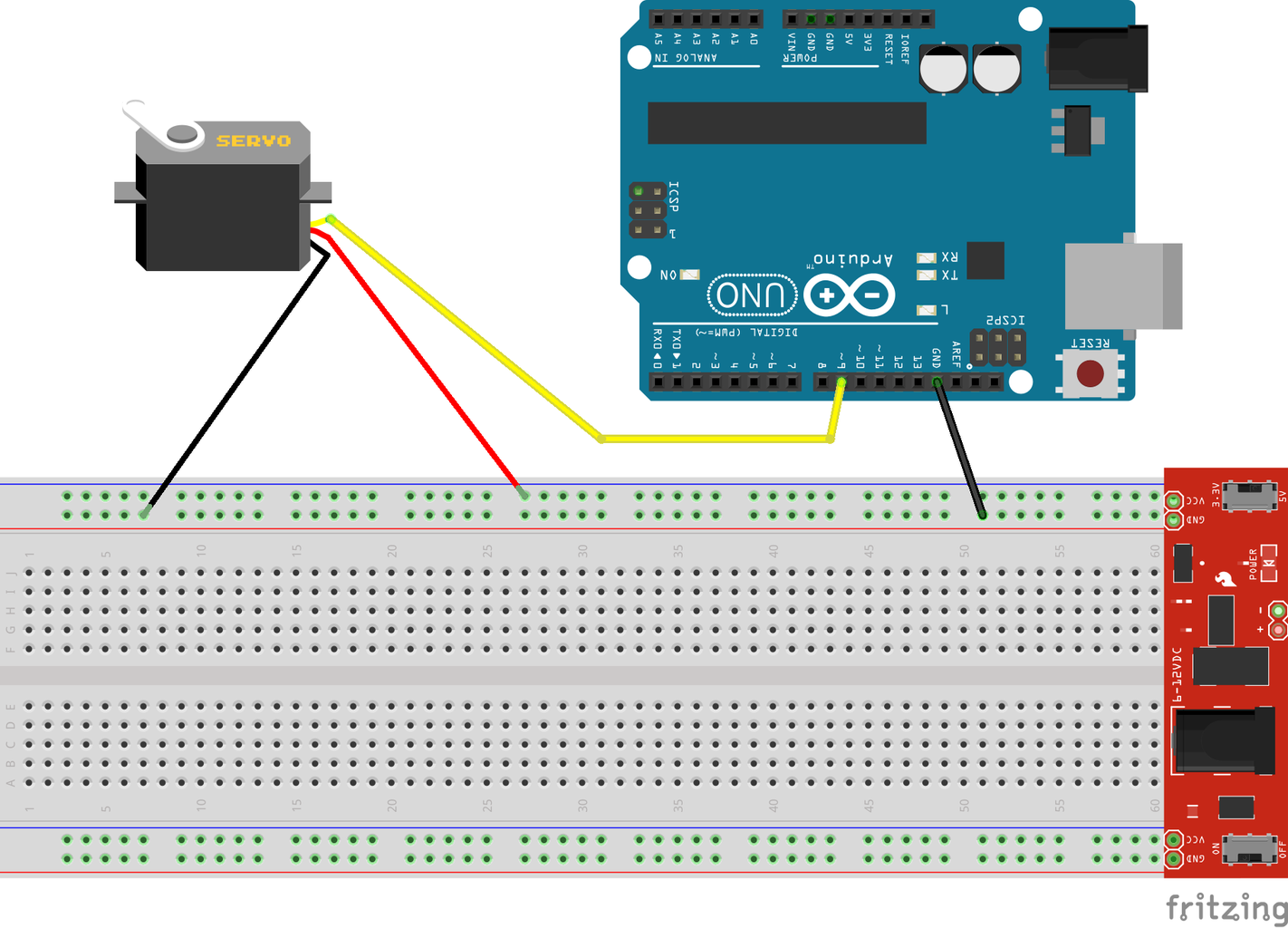
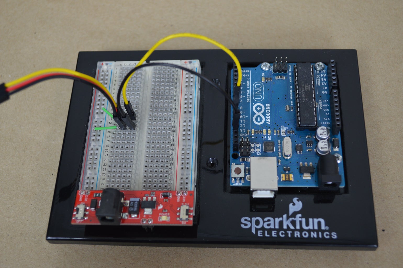
To center the servos, you will need an Arduino, a breadboard, and a power supply. Because it is convenient and easy, I used a breadboard power supply from SparkFun to power the circuit. The trick to centering the servos is that, because the servos we are using for this build are quite powerful, the Arduino cannot drive them directly. Instead, the servos will be powered from the power supply. There is one critically important part of wiring the servo to the Arduino. The servo ground, power supply ground, and Arduino ground MUST all be connected together. The Arduino itself can be powered via its USB port.
The Arduino sketch to center the servo is extremely simple:
#include <Servo.h>
Servo servo1;
void setup() {
servo1.attach(9); // Connect the yellow servo wire to the D9 pin.
servo1.write(90); // Set the servo to mid-point.
}
void loop() {
servo1.write(90);
delay(100);
}
Step 11: Mount Tibias


Next we will mount the tibias to the femurs. This is done in two parts. First, we need to attach the servo horns to the tibias. Second we will attach the femur assembly to the tibia.
The servo horns will attach to the left side of the tibia using M2 screws. Insert the horns so that the shaft goes through the large hole in the tibia.

Once the servo horns are all attached, insert the femur assembly into the space between the mounting arms on the tibia. Press the servo shaft into the servo horn and secure it in place with a screw. On the opposite side, screw an M4 x 12mm screw into the heat-set insert on the back side of the femur assembly. The head of the screw acts as a bearing for the femur-tibia joint.

Step 12: Attach Coxa Covers


Now we will begin assembling the coxa, which we will do in the opposite order we are using for the femur. The first step is to attach the cover pieces to the coxa. Simply place one of the cover pieces on each side of the part, and attach it in place using two M3 x 10mm screws inserted from the inside of the coxa.

Step 13: Mount Servos to Coxa Tops


With the covers in place, the next step in assembling the coxa is mounting the servo. The servo mounts to the coxa the same way the servos mounted to the femur. Place the servo into the coxa top piece with the wire going through the gap in the front two standoffs. Fasten the servo in place with four M3 self-tapping screws.

Step 14: Mount Coxa Bottoms


To complete the coxa assembly, we will mount the bottom cover onto the coxa top. Simply attach the part with four M3 self-tapping screws. Be careful not to tighten the screws too much because you can crack the 3D printed parts rather easily.

Step 15: Attach Coxas to Femurs


Now to join the coxa and the femur/tibia. The process of connecting the coxa to the femur is basically the same as the process we used to connect the tibia to the femur. First we will connect the servo horns to the coxa mounting legs, and second we will connect the coxa itself to the femur.

With the servo horn mounted, connect the femur/tibia assembly by securing the servo to the horn with a screw, and then insert an M4 x 12mm screw on the back side to form the hinge.

Step 16: Connect Femur Covers


At this point, the quadruped's legs are almost complete. The only parts remaining are the left and right femur covers. The femur covers look very similar to the coxa covers we installed earlier, but they are larger. When viewed from the top of the leg, the covers with the slightly taller standoffs go on the left side. The covers attach to the femurs using M3 x 10mm screws.

Step 17: Mount Bearings Into Chassis Bottom


The coxas will be mounted to the chassis on ball bearings to provide low-friction movement since each leg has only a single servo to move the coxa joint. Insert a ball bearing into the bosses on each corner of the Chassis Bottom piece. The bearings fit snugly; you will need to apply pressure to the bearings until they fit into place. Depending upon the dimensional tolerances of your 3D printer, if the bosses are too tight for the bearings, it can be helpful to heat the plastic using a heat gun prior to pressing the bearings into place.
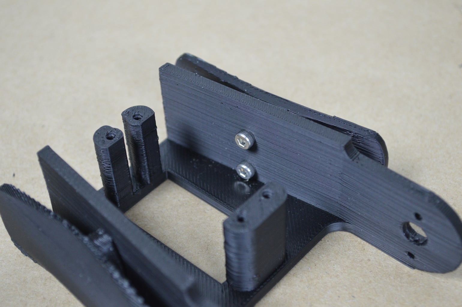
Step 18: Attach Servo Horns to Chassis Top


The servo horns that connect the coxa servos on the legs to the Chassis Top piece connect to the bottom of the part on each corner. On the top of the Chassis Top piece, you will notice that the two smaller holes are countersunk. Insert an M2 x 8mm screw into each of these holes. The heads of the screws should be flush with the 3D printed part. Then, place a servo horn onto each corner and fasten it in place with an M2 nut on the end of each screw.

Step 19: Program the Botboarduino

Of course, in order for all of the servos, 3D printed parts, screws, heat-set inserts, and the assemblies we've created with them to function as a robot, the microcontroller must be programmed. Controlling the robot is certainly not a trivial task, either conceptually or in terms of the computational requirements for the microcontroller. However, it is not too difficult to roughly understand the process the microcontroller goes through to translate commands issued by the user, to a series of servo angles necessary to execute those commands.
The entire process of controlling the robot is just a whole bunch of trigonometric calculations. I have written a couple of articles about the types of calculations used to control legged robots, and if you want to understand exactly how the robot works, you can give them a read. Otherwise, you can simply follow the instructions in the rest of this step to upload the quadruped control code to the Botboarduino.
Programming the Botboarduino
The Botboarduino is derived from the Arduino Duemilanove, so we will use the Arduino IDE to upload the quadruped control code sketch just like you would with any other Arduino board. Head over to the Arduino website and download the IDE if you don't already have it.
Next you'll need the code for the quadruped robot. I store the most up-to-date version of the code in a GitHub repository. Simply download the .zip file from GitHub and extract it to a working directory on your computer.
Before opening the quadruped code in the Arduino IDE, copy the contents of the libraries folder into your Arduino libraries directory. With the libraries installed, open the quadruped in the Arduino IDE.
Before connecting the Botboarduino to the computer, there is a bit of adjustment needed for the board to work that is specific to the Botboarduino. On the Botboarduino, near the power input screw terminals, there is a pin jumper used to select between USB power and external power. In order to program the board, the jumper must be set to the USB power option. Note that after programming the board, we will need to set the jumper for external power instead.
Finally, connect the Botboarduino to your computer. In the Arduino IDE, select Arduino Duemilanove as the board type and make sure the correct COM port is selected. Then, click the upload button.
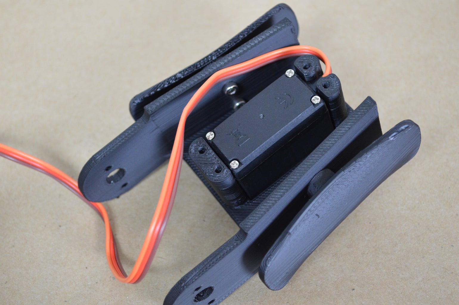
Step 20: Mount Botboarduino Onto Chassis Top


Now that the quadruped code has been uploaded to the Botboarduino, we can get back to assembling the robot. The Botboarduino mounts into the quadruped Chassis Top with the M3 heat-set inserts we installed earlier. Ultimately we will be building a kind of stack of electronics inside the quadruped Chassis with the Botboarduino on the bottom, the controller receiver in the middle, and the SSC-32 servo controller on the top.
To mount the Botboarduino, first, place a 6mm nylon standoff into each of the threaded inserts to make a bit of space for the Boatboarduino. Then, place the Botborduino on top with the USB port and power input screw terminals facing the back of the robot (the side opposite the small fin which will be used for the eye). Fasten the controller in place with four 10mm nylon standoffs.
Step 21: Solder Wires to NeoPixel Ring


The NeoPixel ring does not come with any wires or connectors, so we will need to add a way to connect the NeoPixel ring to the Botboarduino. We will solder three wires onto the NeoPixel ring: one for power, one for ground, and one for the signal input. There are a total of four solder pads on the NeoPixel ring though; the Data Out pin will be left unconnected.
So, solder a black wire to the Ground pad on the NeoPixel ring, a red wire onto the Power pad, and a yellow wire onto the Data Input pad.
Step 22: Mount and Connect NeoPixel Ring


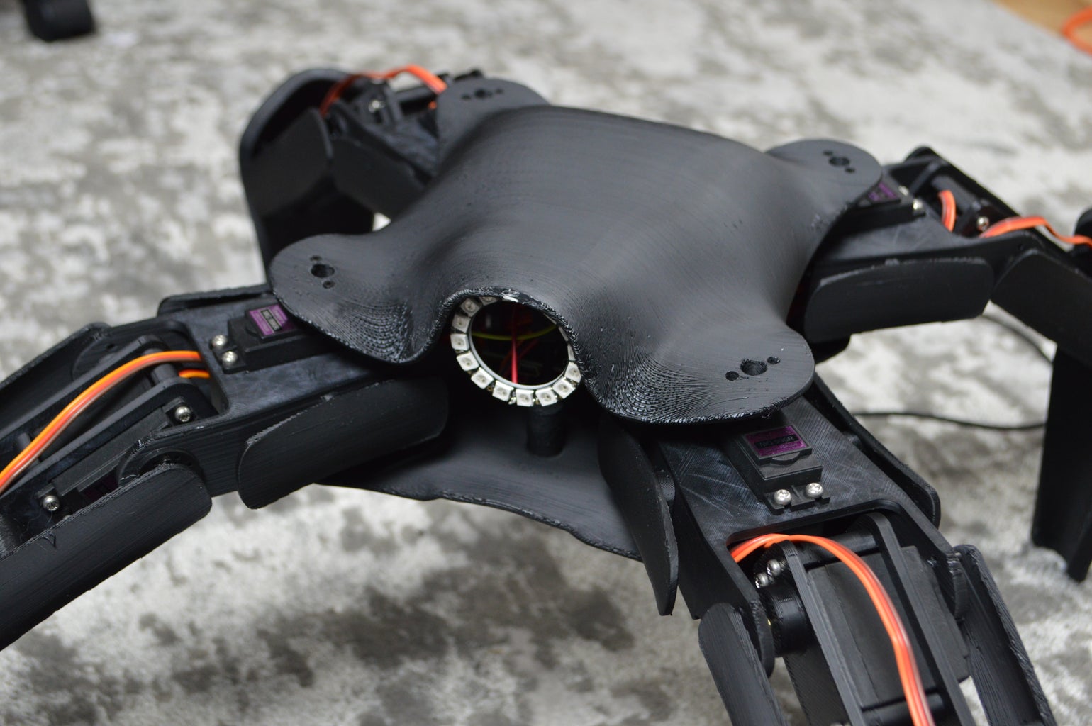
With wires attached to the NeoPixel ring, it is time to mount the ring onto the quadruped Chassis Top piece. On the front of the piece, there is a circular fin. Using hot glue, attach the NeoPixel ring to the front side of this fin. The orientation of the NeoPixel ring is not particularly important.
To connect the NeoPixel ring to the Botboarduino, first connect the black wire to ground and the red wire to 5V. I like to pass the wires underneath the Botboarduino and then back up to connect to the pins for cable management. Then the yellow signal wires connects to GPIO pin 3.

Step 23: Connect Wires for SSC-32 Connection

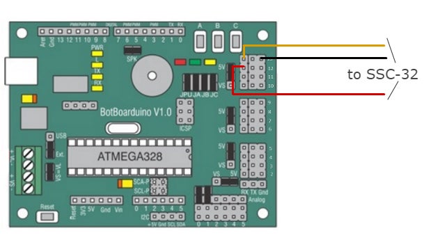
Because we will be placing all of the electronics into a kind of stack inside the robot, there are some wires we need to add now that will connect to other components later on; this will prevent the pins we need to connect from being obstructed by other parts. The first set of wires will eventually connect the Botboarduino to the SSC-32.
The Botboarduino communicates with the SSC-32 over a serial connection; so there are two wires that form the serial connection, plus a ground connection. Place a wire on the ground pin closest to the standoff closest to the set of four jumpers. Then, for the actual serial communication, place a yellow wire on GPIO pin 13 and a red wire on GPIO pin 12.
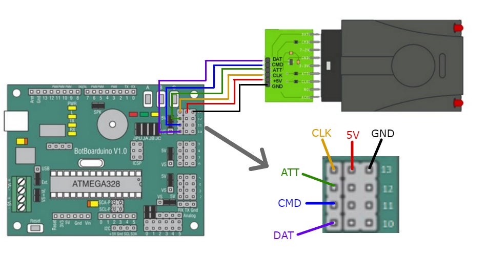
Step 24: Mount and Connect PS2 Controller Receiver


The robot is controlled by a third-party Playstation 2 wireless controller from Lynxmotion. The receiver for the controller will be mounted above the Botboarduino on one of the nylon standoffs already in place. Before attaching the controller receiver to the bundle of electronics inside the robot, we need to connect the controller to the Botboarduino.
There are a total of six pins on the controller receiver.
| PS2 Controller Pin | Botboarduino Pin | |
|---|---|---|
| DAT | connects to | GPIO 6 |
| CMD | connects to | GPIO 7 |
| ATT | connects to | 8 |
| CLK | connects to | 9 |
| GND | connects to | GND |
| 5V | connects to | 5V |
Step 25: Add Power Wires


A single power supply delivers energy to both the Botboarduino and the SSC-32 servo controller. The power supply connects directly to the SSC-32, a setup we will wire in the next step, and then the SSC-32 and Botboarduino power systems are tied together. In this step, we will add a pair of wires to the Botboarduino that will later connect to the SSC-32.
On the Botboarduino, there are two power input screw terminals: one labeled VS and one labeled VL. Connect a black wire to the VL negative screw terminal and a red wire to the VL positive screw terminal. For now the wires will just be left dangling.
Step 26: Connect Power to SSC-32


Now there is a wire attached to the Botboarduino waiting to deliver power to that board from the SSC-32. The SSC-32 will have two power wires connected to it. First, connect a black wire to the negative terminal of the barrel jack adapter and a red wire to the positive terminal.
On the SSC-32, there are three power input screw terminals: VS1, VL, and VS2. There are also three pin jumpers, two on the VS2 side and one on the VS1 side. It should be set up this way out of the box, but make sure all three pin jumpers are connected. This setup basically ties the servo power system and the logic power system together so that both systems can be powered by a single power supply.
Connect the wires from the barrel jack adapter to the VS1 screw terminal using the same polarity as we did on the adapter.
Now connect the wires from the Botboarduino in the previous step to the VS2 screw terminal, matching the polarity. Now the power system goes like this: the power supply delivers power to the left side of the servo power system on the SSC-32, one of the jumpers links the left and right sides of the SSC-32 so both receive power, the second jumper delivers power to the logic circuits on the SSC-32, and finally, the right side of the servo power system on the SSC-32 passes power to the Botboarduino.

Step 27: Mount SSC-32 Servo Controller


Next, we will mount the SSC-32 to the rest of the electronics stack inside on the Chassis Top piece. You should already have a set of female headers on top of the Botboarduino and PS2 controller. Place the SSC-32 on top of these headers with the screw terminals over the screw terminals on the Botboarduino. Fasten the SSC-32 in place using four M3 nylon screws.
Step 28: Connect Leg Sub-assemblies to Chassis Top


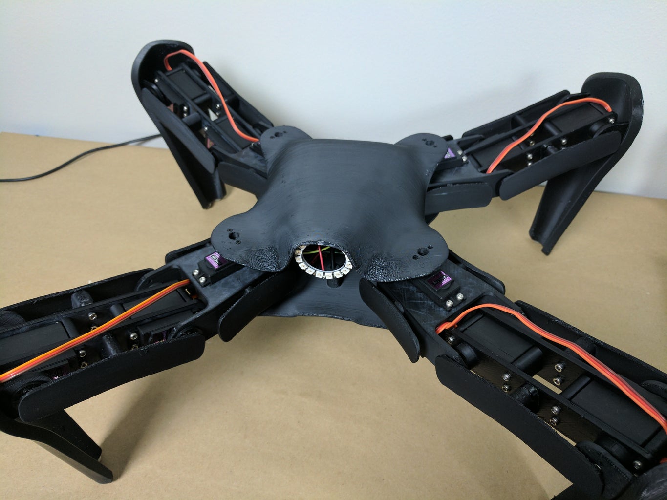
This is the part of the build where I start to get excited because the finished shape of the quadruped robot is finally emerging from the pile of parts with which we began this Instructable. The quadruped's legs are complete at this point and so is the Chassis Top and the electronics parts connected to it. In this step, we will connect the legs to the Chassis Top part.
For each leg, use medium pressure to press the coxa servo shaft into the servo horn. It is very important that the leg be placed at a 45o angle to the edges of the Chassis Top. In other words, it should extend straight out the corner of the Chassis Top. Secure the legs in place with the servo screws.
Before the Chassis Bottom is connected in the next step, the relativly large and heavy legs are only supported by the servo horn. Therefore, care must be taken when working with the robot to avoid breaking the servo horn.

Step 29: Connect Servos and Botboarduino to SSC-32


With the legs connected to the body, the servos need to be wired to the SSC-32 servo controller. The SSC-32 can control up to, as the name implies, 32 servos. On the SSC-32 board, the servo connections are arranged in sets of four along the edges of the board. Each row of three servo connection pins is identified with a number. The servos connect to the SSC-32 according to the table and image below:
| Servo Position | SSC-32 Pin |
|---|---|
| Rear Right Coxa (Horizontal) | 0 |
| Rear Right Femur (Vertical) | 1 |
| Rear Right Tibia (Knee) | 2 |
| Front Right Coxa (Horizontal) | 8 |
| Front Right Femur (Vertical) | 9 |
| Front Right Tibia (Knee) | 10 |
| Rear Left Coxa (Horizontal) | 16 |
| Rear Left Femur (Vertical) | 17 |
| Rear Left Tibia (Knee) | 18 |
| Front Left Coxa (Horizontal) | 24 |
| Front Left Femur (Vertical) | 25 |
| Front Left Tibia (Knee) | 26 |

Step 30: Attach Chassis Bottom


Finally there is but one more part to attach to the robot and then it will be complete! The Chassis Bottom part has a slightly flatter shape on one side. This side is the front. Place the Chassis Bottom piece onto the legs so that the pegs on the bottom of the coxas slip into the ball bearings on each corner of the Chassis Bottom. To fix the Chassis Bottom in place, use the M4 x 50mm screws inserted through the Chassis Bottom and threaded into the M4 heat-set inserts we installed in the Chassis Top earlier.

Step 31: Control Your Quadruped


Congratulations! Your 3D printed quadruped robot is now complete. The only thing left to do is turn it on and take it for a walk.
To turn on the robot, simply plug it in to the power supply. Be a bit careful when you do this because it is likely the legs will jerk suddenly as they are first delivered power and the Botboarduino initializes.
The Botboarduino can be armed or disarmed for motion using the PS2 controller. To arm the robot and enable it to accept your commends, press the start button on the PS2 controller. The Botboarduino will confirm it is armed with a single beep.
After that, review the diagram below for the quadruped's control setup.
Have fun with your new robot! Your new quadruped can even thank you with a bow.

Credits
- CAD design: Autodesk Fusion 360
- Assembly animation: Autodesk Fusion 360
- Animation .gifs: GIPHY
- Wiring diagrams: Autodesk Pixlr
- 3D printing: 3D Hubs

First Prize in the
Epilog Contest 8

Second Prize in the
Design Now: 3D Design Contest 2016


