

Introduction: A Universal RFID Key


RFID projects have been pretty prominent recently, ranging from projects here in Instructables, to our local Silicon Chip magazine in Australia publishing a RFID door lock project in their November issue. Even I recently purchased a RFID door lock on eBay for $15 to lock my garage (so my front neighbor could get tools if he wanted to).
We have known that the cheaper RFID technologies were pretty insecure for a number of years. Researchers have demonstrated cloners of all varieties, but simple RFID tags are still being used for access control. Even my current employer uses them.
A while ago, I was looking at Hack A Day, and I saw an amazing project that somebody had made. It was an RFID card with a keypad on it. For the next couple of days, I couldn't get the image of the card out of my mind; the project reminded me of how much I wanted to build a RFID spoofer myself. The original author didn't release source code for their project, but they left enough clues that I could follow.
So, in typical fashion, I built my own reader hardware so I could have a look at the data from a card, and created my own version of the Universal RFID key.
The key I made works beautifully both on my garage door, as well as a number of other RFID readers I have tried!
I have decided to publish this, as more people should be aware of the design flaws that are inherent in older RFID implementations, and to allow others to make their own universal key.
Will this key let you into anybodies RFID protected office? Yes it will, assuming a couple of things are true
1) The have to be using 125kHz RFID tags that use the same encoding standard as I have designed this project for, and,
2) You have to have access to the number printed on the back of the tag - with that number, you can simply key it into the Universal RFID key, and it will emulate that tag.
So there you go - I hope you enjoy making this project. - And remember, with great power comes great responsibility!
Step 1: How Does RFID Work?

RFID, or Radio Frequency IDentification is the term used to describe a wide variety of standards that allow data stored within electronic 'tags' to be read by a reader without using wires. There are a number of standards, encoding formats, and frequencies in common use. I will describe the 125 kHz standard that is common for access control mechanisms.
125 kHz RFID tags are commonly encased in a business card sized piece of plastic, or a round disk. The tag consists of a coil of wire, connected to a microchip. When the tag is brought into close proximity to a reader, energy is coupled inductively from the reader to the microchip within the tag.
The energy from the reader has dual use; firstly, it provides power to run the card, and secondly, it provides a communication medium for data to be transmitted. Once powered up, the tag modulates the bit pattern that is programmed into the tag using a signal that the reader can detect. The reader then reads this bit pattern, and passes it onto the door controller. If the bit pattern matches one that is authorised, the door will be unlocked. If the bit pattern does not match an authorised one, then the door won't unlock.
In the RFID system I was playing with, the bit pattern looked like this;
1111111110010111000000000000001111100010111110111101001111010000
I will describe what this pattern actually means in the next page.
One interesting feature of the data transfer between the card and the reader, is that data is encoded using Manchester Encoding, which is a way of encoding data so that it can be transmitted over a single wire ensuring that the clock information is able to be recovered easily. With Manchester encoding, there is always a transition in the middle of a bit. If you want to transmit a 1, the transition would be from low to high, and if you want to transmit a 0, the transition would from from high to low. Because the transitions are in the middle of each bit, you can ensure that you have locked onto valid data. For a detailed description, have a look a this page.
The actual data is transmitted by the card effectively shorting the coil out - this applies an additional load to the transmitter in the reader, which can be detected.
Step 2: Whats Stored on the Card?


I started by building a RFID card reader (more details in a future article). That showed me the data that was being sent when the card transmitted its information.
The RFID cards that I brought have numbers printed on the back of them. This number says what data the card has included in it.
the card with 0007820706 119,21922 printed on it transmits this pattern:
1111111110010111000000000000001111011110101001010101000010101100
The first set of 111111111 bits are the start sequence - it is used to tell the reader that a code is coming - the reader also uses the sequence to lock onto the card data.
Data stored is transmitted in groups of 4 bits, with a parity bit at the end of every group.
The data can be broken up as follows;
00101 11000 00000 00000 01111 01111 01010 01010 10100 00101 0110 0
If we ignore the parity bit at the end of every nibble we have
0010 1100 0000 0000 0111 0111 0101 0101 1010 0010 0110 0
2 C 0 0 7 7 5 5 A 2 CHECKSUM STOP
This code is 2c 0077 55a2 if we break the code into 3 groups, we have 2c, followed by 0077 (which is 119 in decimal), and finally 55A2, which is 21922 in decimal - this corresponds to the 119,21922.
The same number is also written in another way on these cards 0007820706 (in decimal) is simply the hexadecimal number 7755A2.
WOOT we now understand how the data is stored.
2C is a constant code that is sent with all of the cards. It is simply a facility identifier for this RFID system.
How does the parity and checksum work?
One final piece of data that the card transmits is a checksum word - this is used to ensure that all of the data has been received successfully. Firstly, the parity bit at the end of each nibble of data is Even parity - this means that the transmitter will add a 1 to make sure that each block of data has an 'even' number of '1' bits - So if we look a the '2', which is 0010 in binary - the parity system would detect that there was an odd number of '1' bits, and would add one to compensate. Compare that to the 'C' which is 1100, the parity system would detect that there are an even number of '1' bits, so it would add a zero.
00101 2
11000 C
00000 0
00000 0
01111 7
01111 7
01010 5
01010 5
10100 A
00101 2
0110 checksum + 0 stop bit
Finally, the checksum is an even parity bit applied to each of the vertical row bits. This way, there is a horizontal and vertical check of every bit sent - everything has to line up, or the reader will simply reject the transmission.
When I decoded the data for my work prox card, it followed a similar sequence here, but (for obvious reasons) I won't actually publish the numbers. Again, part of the sequence was a facility code, and the rest of the sequence held the same number that was printed on the back of the card.
Step 3: How Do We Emulate a Card?

So the next step was to identify how to pretend to be a card - I wanted a card that I could type a card number into, so it had to have a microprocessor on it, was well as a keypad to allow the data to be keyed in.
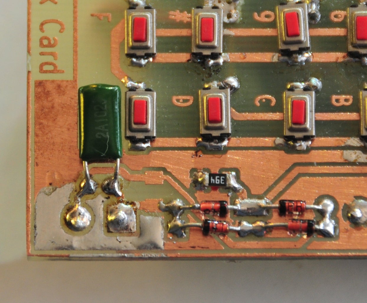
The ATMega manipulates the 125kHz RF field by using a bridge rectifier. When the output of the micro is low, the diodes in the bridge are allowed to be turned on by the current induced in the coil, this effectively short it out. The reader detects the additional load, and a bit transition is detected.
The job of the micro is simply to turn the output on and off in a way that makes sense to our reader. So I created a board that had the micro, a power supply, keypad, and some status LEDs on it.
The attached PDF is the full schematic of the project.
You may notice that c6 is 0pF - That is intentional c6 is a placeholder component allowing me to either use a 1000pF surface mount cap, or a 1000pF through hole cap.
The coil is 100 turns of fine wire would on an open former that is just smaller than the card border.
Attachments

Step 4: The Software - Entering Data Into Our Card
The software was next. Using the Arduino IDE, I implemented a simple menu system that allowed me to enter the relevant facility and CardID data directly from the keypad. I also provided a way of displaying the data using the LEDs that I mounted on the board.
One problem I came across, was when I was calculating the card data (parity and checksum) on the fly - To be read successfully, the card has to output data in real time (most readers need a number of sequential valid reads), and adding subroutine and calculation delays caused the card to output invalid data as far as the reader was concerned. I worked around this problem by populating an array of bits that gets sent when the card is in transmit more. That way, the calculations are done only once.
When the card is powered up, it waits for the 'mode' button to be pressed. The current mode number is displayed using a set of 4 LEDs. Each press on the 'mode' button increments the current mode. Once the correct mode is displayed, then the 'enter' key starts that function executing.
MODE 1 - Enter low power (sleep) mode
The card enters a low power mode, waiting for the reset button to be pressed to re-awaken it
MODE 2 - Enter a Hex Facility ID
The card waits for 2 digits to be entered signifying the facility code for this system (In this case, it is 2C) - The software defaults to 2C - so this does not need to be entered.
MODE 3 - Decimal Card ID
The card waits for 8 digits to be entered signifying the CardID for the card to be spoofed (In this case, it is 07820706) - This is the long number printed on the back of the card, not the 119,21922 number.
MODE 4 - Dump the facility and Card ID
The Facility and Card ID are Dumped as Hex numbers using the 4 Leds at the top of the card.
MODE 5 - Emulate a card
The card enters emulation mode - all LEDs are turned off. Emulation mode can only be exited by pressing the reset button.
The software relies on Mark Stanley's and Alexander Brevig's Keypad Library http://www.arduino.cc/playground/Code/Keypad
Attachments

Step 5: Etching the PCB

As per standard, I used toner transfer onto magazine paper to etch a board. If you want to see the details, have a look here.
The etched PCB had its edges cleaned up a bit using a file, and holes were drilled for the IC legs.
Attached are the PDF files that I used for the Toner Transfer.
Step 6: Mounting the Components


To keep the project the same size as a normal prox card, I decided to make it on a small PCB that was the same size as a business card.
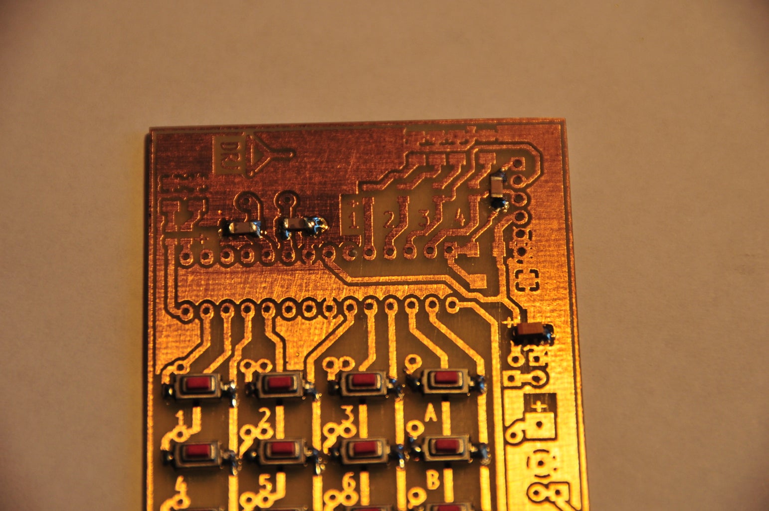
I decided to use surface mount push buttons that I brought from eBay, so that meant that all of the components must be soldered onto the copper side of the PCB to allow the buttons to be mounted and labeled.
I started by soldering the push buttons, then I mounted the LEDs, resistors and capacitors. I had to install the 16MHz crystal on the bottom of the PCB, as I did not have a surface mount crystal. I also installed 12 jumpers on the back of the card to connect the key columns together.
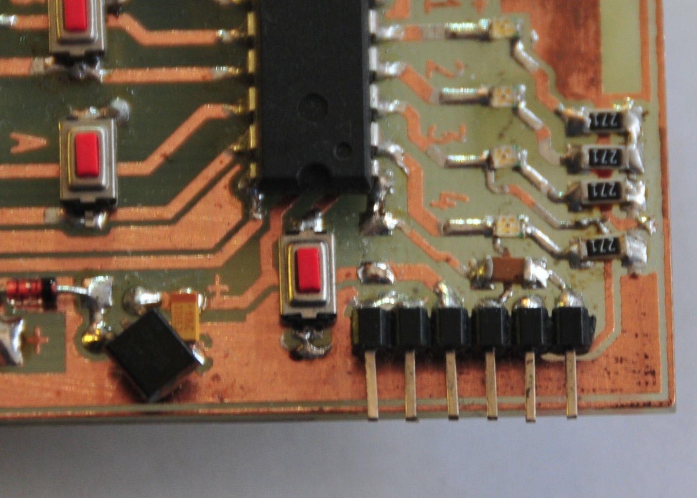
The ATMega168 was mounted next. I did not use a socket, as I wanted to reduce the board thickness.
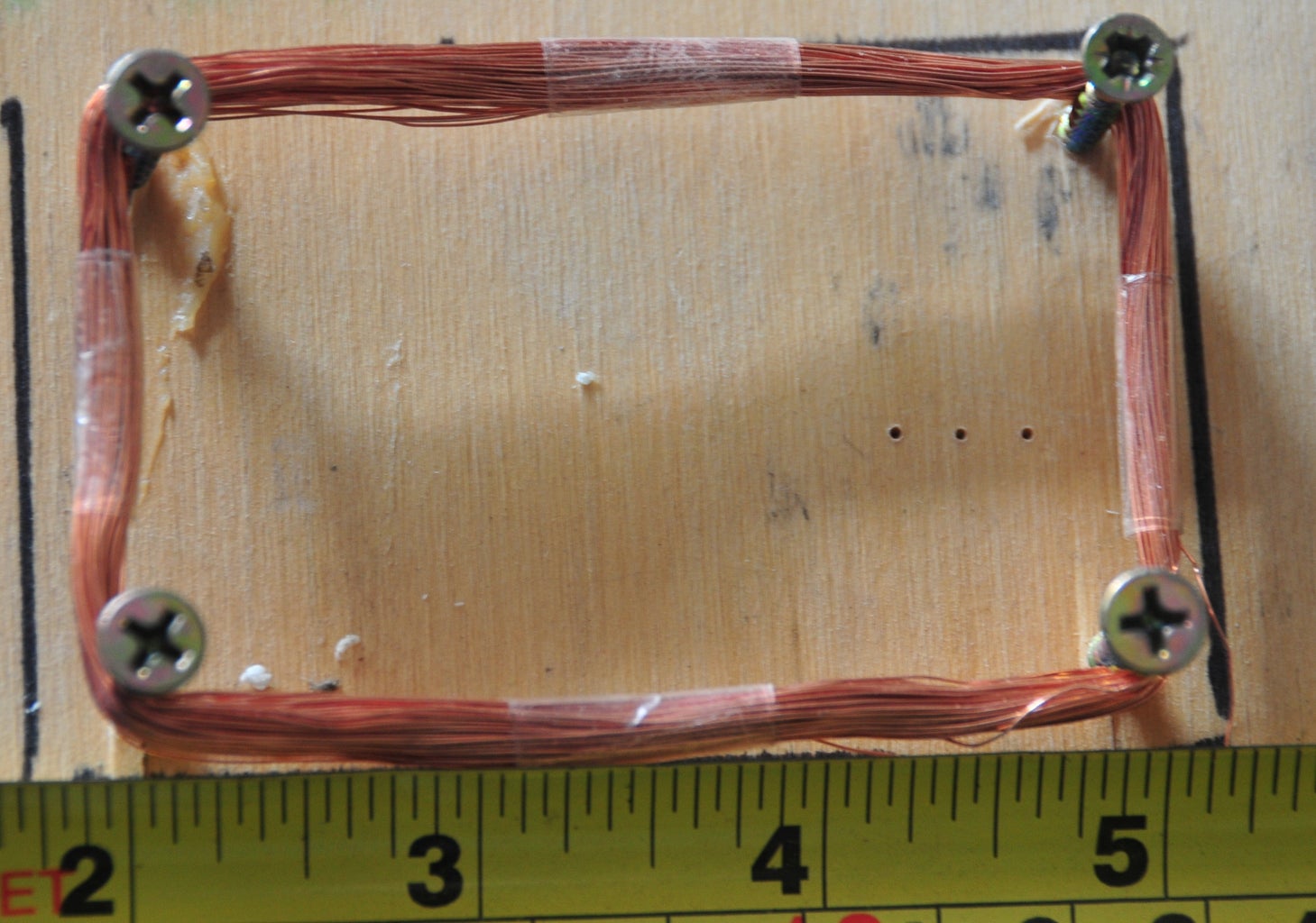
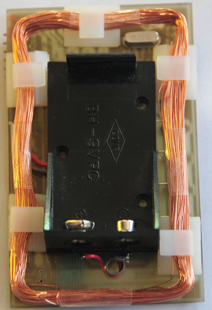
Next, I wound the coil - I used a piece of scrap timber, with 4 screws mounted on it, and counted 100 turns of 0.25mm diameter coil winding wire. Before I removed the coil from the mounts, I wound a small amount of clear tape around each edge to make sure that the coil didn't unwind.
Then, I mounted the coil on the back of the PCB, along with a small battery holder.
I was pretty happy with the result of my handiwork.
Step 7: Programming the Micro
I used a standard 6 pin header mounted on the PCB to allow a FTDI 5V USB-232 cable to be used to program the chip in-situ - this was especially important, as the ATMega chip is soldered directly to the PCB, so it couldn't be removed for insertion into a normal Arduino PCB- This is a small price to pay to have a nice compact project.
The chip was programmed using the .pde Arduino sketch that was supplied in Step 4 - using the normal Arduino IDE.
The .PDE file that I have provided is tailored to the standard cheap eBay RFID systems. It is not the version for the other IFID readers I have access too..... (I just thought I would mention that :-) )
Step 8: Testing the Project

Testing was a breeze - I typed the relevant code into the keypad, swiped the board against the reader, and was rewarded with a satisfying 'BEEP' indicating that the read was successful.
Testing at the other readers I have access to was just as rewarding, and scored infinite geek points!!!
Step 9: Further Steps
This was a 'to prove I could do it' project - I have completed it, so it now sits on my shelf at work to remind others that simple RFID systems are simply not secure.
You are welcome to adapt the project however you would like to, and while you may have the skeleton keys to the kingdom, you still need the little numbers on the back of the access card before you can use the key yourself.
I have considered modifying my card so that it works as all of the compatible RFID tags that I hold. In my job, I need have access to multiple work sites, and it would be great to use the one card, but I don't think that would be a great idea..........
Will this work on all RFID sytems?
No it won't. This is a good thing.
The first RFID systems deployed years ago used very simple protocols, based on the intelligence of the chip in the card - They also used a low frequency (125kHz) carrier.
More modern systems use a number of techniques to ensure security, such as one time codes; cryptography; use bi-directional communication; use internal passwords, and use much higher frequencies. So spoofing these systems is a lot more work.
But there are a large number of low tech systems in place now.
What can I do to protect my system?
Firstly, don't equate cards to physical keys - in simple systems they are not equivalent.
Don't give out visitor cards - They are easily duplicated - I f you do need Visitor cards, then implement a system where they are only active when they have been issued.
Enable Pass Back systems - If the card system believes you are in a particular room, make sure that the card can't be used in other rooms at the same time.
Remove the numbers from the back of the cards - while they may make it easier to enter card details, but they also make it easy for somebody to use the details for their own purposes.
Finally, look at how to upgrade your access system to a card system that is not trivially spoofed using $15 worth of parts. And - No, purchasing a new system from eBay for $15 is not the answer....


