

Introduction: ASPIR: Full-Size 3D-Printed Humanoid Robot


Autonomous Support and Positive Inspiration Robot (ASPIR) is a full-size, 4.3-ft open-source 3D-printed humanoid robot that anyone can build with enough drive and determination.
Table of Contents
We've split this massive 80-step Instructable into 10 easy-to-read chapters linked below for your reading convenience:
Notes: This is a very advanced and large Instructables project! We recommend you have significant 3D-printing experience before attempting this project. Expected build time will be several months with an estimated build cost of roughly $2500 (this cost may be lower or higher depending on which suppliers you use and which parts you already have). Note that this Instructable only covers the hardware construction, and not the software (this is currently under development). With that being said, full speed ahead and good luck!
Step 1: About ASPIR

ASPIR is the spiritual successor to Halley, the Ambassador Robot 001 (2015), a popular low-cost, open-source, 2.6-foot laser-cut humanoid robot. Over the course of showcasing the Halley Robot, we've found that humanoid robots are awesome at looking human and eliciting social-emotional responses from human viewers. There are plenty of humanoid robots out there for sale, but they all really fall into just two categories: affordable toy hobbyist robots that are less than 2-feet tall, and full-size, and research-grade humanoid robots that cost more than new sports cars. We wanted to bring the best of both worlds together with an affordable, open-source full-size humanoid robot. And thus the ASPIR project was born.
(P.S. A great big thank you to Discovery Channel Canada's Daily Planet for producing the video! :D)
Step 2: About Us

Choitek is an advanced educational technology company committed to preparing the students of today to become the artists, engineers, and entrepreneurs of tomorrow by building the biggest, boldest, and most incredibly awesome robots to teach and inspire. We are passionate members of the open-source community and believe that learning is maximized for the good of everyone when there are no proprietary black boxes that exist to conceal and obfuscate technology. With that being said, we hope you'll join us in this exciting adventure of building the future of robotics together.
(Note: our company is currently doing research in seeing how humanoid robots like ASPIR can be used to inspire more girls into STEM. If you are interested in collaborating with us, feel free to let us know!)
Step 3: Special Thanks

The ASPIR Project is made possible with the generous support of the Frank-Ratchye STUDIO for Creative Inquiry of Carnegie Mellon University:
"The Frank-Ratchye STUDIO for Creative Inquiry is a flexible laboratory for new modes of arts research, production and presentation. Founded in 1989 within the College of Fine Arts at Carnegie Mellon University (CMU), the STUDIO serves as a locus for hybrid enterprises on the CMU campus, the Pittsburgh region, and internationally. Our current emphasis on new-media arts builds on more than two decades of experience hosting interdisciplinary artists in an environment enriched by world-class science and engineering departments. Through our residencies and outreach programs, the STUDIO provides opportunities for learning, dialogue and research that lead to innovative breakthroughs, new policies, and the redefinition of the role of artists in a quickly changing world."
Step 4: Servos, Servos, Servos

With 6 super-size mega servos per each leg, 4 high-torque standard servos for each arm, 5 metal-gear micro servos for each hand, and 2 additional standard servos for the head's pan/tilt mechanism, the ASPIR robot's actuators move with a staggering total of 33 degrees of freedom. For your reference, we have included sample reference links to various servomotors you will need to build the ASPIR robot:
(Note: Servo cost and quality is highly variable depending on which supplier you use. We've provided some sample links to help you along your way.)
Step 5: Electronics, Electronics, Electronics


In addition to 33 high-torque servomotors, you will also need a variety of other electronic components to control and power the ASPIR robot. For your reference, we have included sample reference links to other electronic and mechanical components you will need to build the ASPIR robot:
- 1x USB Webcam
- 1x 4-port USB Hub
- 1x Laser Rangefinder
- 8x RC Shock Absorbers
- 1x Arduino Mega 2560 R3
- 1x Arduino Mega Servo Shield
- 5.5-In Android Smart Phone
- 50x Servo Extension Cables
- 2x 5V 10A Power Adapters
- 8x 210mm x 6mm Aluminum Hex Rods
- 4x 120mm x 6mm Aluminum Hex Rods
- 4x 100mm x 6mm Aluminum Hex Rods
- 2x 75mm x 6mm Aluminum Hex Rods
- 1x 60mm x 6mm Aluminum Hex Rods
(Note: While these parts provided in the links above will be electronically compatible, keep in mind that the exact CAD dimensions needed to adapt certain electronic and mechanical parts may vary by component.)
Step 6: 300 Hours of 3D Printing!


As mentioned in the introduction previously, the ASPIR is a supermassive 3D printing endeavor. With over 90 parts to print, total estimated print time using standard 3D filament extrusion, infill and layer height settings is expected to be somewhere in the ballpark of 300 hours. This will likely consume 5 rolls of 1 kg (2.2lb) filament, not including printing failures and retries (We used Robo3D PLA rolls for all our 3D printing needs). Also note that you will need a large 3D printer with a minimum build plate size of 10x10x10in (250x250x250mm), such as the Lulzbot TAZ 6 for some of the larger 3D printed pieces of the ASPIR robot. Here are all of the files you will need to 3D print:
Once you've got all the parts, let's begin!
Step 7: Arms 1

To begin, we'll start with our 3D printed hands. These hands are specially designed to be flexible even when printing with PLA. Attach 5 micro servos, one for each finger on the 3D printed hand.
Step 8: Arms 2

Now, attach the wrist piece to the hand with two screws. Then slot the 100mm aluminum hex rod into the wrist piece.
Step 9: Arms 3

If you have not done so already, go ahead and route string onto the micro servo's horns with the forward-leading edge nubs on each of the fingers. Be sure to tie a firm knot on each of the fingers, and minimize string slop by making a tight connection between the micro servo horn, the string and the leading-edge nub on each finger.
Step 10: Arms 4


Continue the construction of the arms by attaching the lower arm piece to the end of the hex rod. Attach a standard servo to the lower arm piece and secure it with 4 screws and washers.
Step 11: Arms 5


Continue the assembly of the arm by attaching the servo horn hinge part to the lower arm and fasten it with 4 screws.
Step 12: Arms 6

Now, extend the upper arm by slotting another 100mm aluminum hex rod into the hinge joint, and fasten another 3d printed hinge joint on the other end of the 100mm aluminum hex rod.
Step 13: Arms 7

We are now assembling the shoulder joint. Begin by grabbing another standard servo and secure it to the first shoulder piece using 4 screws and 4 washers.
Step 14: Arms 8

Slot and fasten the shoulder assembly to the rest of the shoulder pieces. The bottom circular piece should be able to pivot on the servo's gear axis.
Step 15: Arms 9

Connect the shoulder assembly to the upper arm servo motor with the last shoulder piece with 4 additional screws.
Step 16: Arms 10


Combine the shoulder assembly with the lower/upper arm assembly at the swivel point at the top of the arm assembly. The parts should join at the upper arm's hinge joint. This concludes the assembly of ASPIR's arm.
(Note: you will need to repeat all ten steps for the arm assembly for the other arm, as ASPIR has two arms, left and right.)
Step 17: Head 1

We are now assembling ASPIR's head. Begin by attaching a standard servo to the robot's neck piece with 4 screws and 4 washers.
Step 18: Head 2

Like the pivoting shoulder assembly earlier, attach a pivoting circular head to the standard servo horn, and secure it with the circular head holder.
Step 19: Head 3

Now attach the base platform of the robot's head onto the circular neck pivot mechanism from the previous step with four screws.
Step 20: Head 4

Attach another standard servo to the base platform with 4 screws and 4 washers. Attach head tilt linkages to the servo's horn. Make sure the head tilt linkages are able to spin freely.
Step 21: Head 5


Attach the phone face plate holder onto the front of the base platform. Connect the back of the phone face plate holder onto the servo tilt linkages. Make sure the head can rotate back and forth 60 degrees.
Step 22: Head 6

Slide the 5.5-inch Android phone into the phone face holder. (A slim iPhone with the same dimensions should do the trick as well. Phones with other dimensions have not been tested.)
Step 23: Head 7

Secure the phone's position by fastening the laser rangefinder on the left side of the robot's face with 2 screws.
Step 24: Head 8

Slot in a 60mm aluminum hex rod into the bottom of the robot's neck. This concludes the assembly of the robot's head.
Step 25: Legs 1

We are now beginning assembly of ASPIR's legs. To start, fasten the robot's forward and hind foot pieces together with two large screws. Make sure the forefoot is able to spin freely.
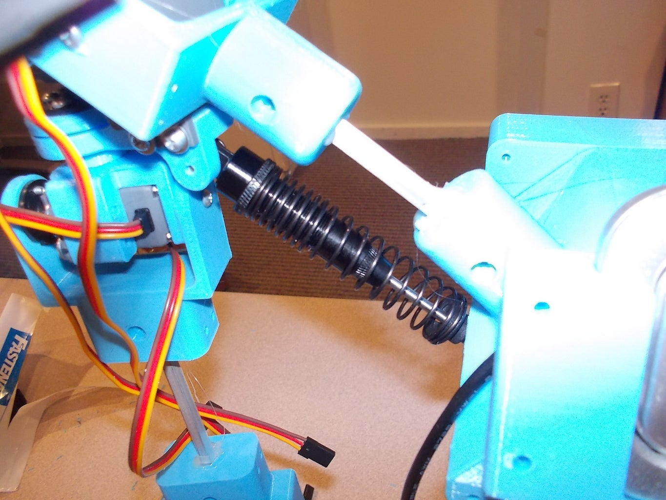
Step 26: Legs 2

Attach 2 RC shock absorbers on the forward and back foot pieces as shown. The foot piece should now flex around roughly 30 degrees and bounce back.
Step 27: Legs 3

Begin assembling the ankle with two extra large servos, and fasten them together with 4 screws and 4 washers.
Step 28: Legs 4


Complete the connection with the other ankle piece and fasten the connection with 4 more screws and washers.
Step 29: Legs 5

Attach the foot connector piece with one large screw on the back and 4 small screws on the servo horn.
Step 30: Legs 6

Attach the top ankle connector to the rest of the ankle assembly on the other large servo with 4 small screws and one large screw.
Step 31: Legs 7

Slot two 210mm hex rods to the ankle assembly. On the other end of the hex rods, slot the lower knee piece.
Step 32: Legs 8

Fasten an extra large servo onto the knee piece with 4 screws and 4 washers.
Step 33: Legs 9

Connect the upper knee piece onto the knee's large servo motor horn with 4 small screws and 1 large screw.
Step 34: Legs 10

Slot two more 210mm hex rods onto the knee assembly.
Step 35: Legs 11

Begin construction of the thigh by slotting a 5V10A power adapter into the two power adapter holder pieces.
Step 36: Legs 12

Slide the thigh assembly into the 2 hex rods on the robot's upper leg.
Step 37: Legs 13

Lock the thigh into place by slotting a hinge joint part onto the 2 hex rods on the upper leg.
Step 38: Legs 14

Begin the hip joint assembly by connecting the large circular head onto a large servo motor's horn.
Step 39: Legs 15

Slide the hip servo holder onto the large servo motor and fasten 4 screws with 4 washers.
Step 40: Legs 16

Slide the hip servo assembly into the other hip piece so that the pivot joint can spin. Fasten this piece into place with 4 screws.
Step 41: Legs 17

Attach another large servo onto the hip assembly with 4 screws and 4 washers.
Step 42: Legs 18

Fasten an upper leg servo holder part with 4 screws, on the circular pivot joint.
Step 43: Legs 19

Fasten an extra large servo onto the large part upper leg servo holder from the previous step with 4 screws and 4 washers.
Step 44: Legs 20

Connect the completed hip assembly onto the rest of the leg assembly at the upper leg hinge joint part. Fasten it with 4 small screws and one large screw.
Step 45: Legs 21

Connect the foot assembly onto the bottom end of the rest of the leg assembly and secure it with 6 screws. You are now done with the leg assembly for now. Repeat steps 25-45 to create the other leg so that you have both right and left legs for the ASPIR robot.
Step 46: Chest 1

Begin the chest assembly by fastening large circular servo horns on the left and right sides of the large pelvis piece.
Step 47: Chest 2

Slot four 120mm hex rods onto the pelvis part.
Step 48: Chest 3

Slide an Arduino holder plate onto the back two hex rods. Slot the lower torso piece onto the four hex rods.
Step 49: Chest 4

Attach an extra large servo onto the lower torso piece and fasten it into place with 4 screws and 4 washers.
Step 50: Chest 5

Connect an extra large circular servo horn onto the upper torso piece with 4 screws.
Step 51: Chest 6

On the back of the upper torso piece, attach the back switch guard piece with 5 screws.
Step 52: Chest 7

Fasten the webcam holder on the front of the upper torso assembly with 3 screws.
Step 53: Chest 8

Slot a USB webcam into the webcam holder.
Step 54: Chest 9

Connect the upper torso assembly with the lower torso assembly at the extra large servo horn.
Step 55: Chest 10

Attach an Arduino Mega 2560 onto the back Arduino plate with 4 screws and 4 spacers.
Step 56: Chest 11

Connect the Arduino Mega Servo Shield directly on top of the Arduino Mega 2560.
Step 57: Merging 1

Connect the head assembly with the torso assembly between the neck hex rod and the upper torso piece.
Step 58: Merging 2


Merge the left and right and left arm assemblies with the rest of the torso assembly at the shoulder's hex rods.
Step 59: Merging 3
Fasten RC shock absorbers beneath both arm hex rod connections. Make sure the shoulder assembly can flex about 30 degrees outwards.
Step 60: Merging 4


Merge the left and right legs together to the rest of the torso assembly at the large hip servos. Use large screws to secure the pivot joints.
Step 61: Wiring 1

On the back of the robot, attach a 4-port USB hub directly above the Arduino Mega Servo Shield.
Step 62: Wiring 2


Begin wiring all 33 servos to the Arduino Mega Servo Shield using the servo extension cables. Also hookup the laser distance rangefinder from the robot's head onto the Arduino Mega Servo Shield. We recommend using standard cable ties to help organize the wires.
Step 63: Wiring 3

Finally, complete the wiring by connecting the Arduino Mega, the Android phone, and the webcam onto the 4-port USB Hub using standard USB cables. Attach a USB extension cable to extend the length of the 4-port USB Hub source.
Step 64: Shells 1

Begin getting the shells of the head by fastening connector plates on the inside of the robot's back head shell piece.
Step 65: Shells 2

Attach the robot's front face shell piece onto the phone plate holder. Fasten it with 4 screws.
Step 66: Shells 3


Screw on the robot's back head shell piece onto the robot's front face shell piece.
Step 67: Shells 4

Connect the back shell piece of the neck onto the robot's neck assembly. Make sure the neck wires are fit snugly inside.
Step 68: Shells 5

Connect the front shell piece of the neck onto the robot's neck assembly. Make sure the neck wires are fit snugly inside.
Step 69: Shells 6


For each of the left and right lower arms, screw on a back lower arm shell piece.
Step 70: Shells 7

For each of the left and right lower arms, screw on a front lower arm shell piece. Make sure the arm wires are snugly fit.
Step 71: Shells 8

For each of the left and right upper arms, screw on a back upper arm shell piece. Make sure the arm wires are snugly fit.
Step 72: Shells 9

For each of the left and right lower arms, screw on a front upper arm shell piece. Make sure the arm wires are snugly fit.
Step 73: Shells 10


For each of the left and right lower legs, screw on a back lower leg shell piece. Make sure the leg wires are snugly fit.
Step 74: Shells 11

For each of the left and right lower legs, screw on a front lower leg shell piece. Make sure the leg wires are snugly fit.
Step 75: Shells 12

For each of the left and right upper legs, screw on a front upper leg shell piece on the power adapter holder thighs. Make sure the leg wires are snugly fit.
Step 76: Shells 13

For each of the left and right upper legs, screw on a back upper leg shell piece on the power adapter holder thighs. Make sure the leg wires are snugly fit.
Step 77: Shells 14

For the front and back of the ASPIR robot's lower torso, attach a front shell piece. When you are done, screw on a back lower torso piece as well.
Step 78: Shells 15

Attach the front upper torso shell piece onto the front of the ASPIR robot's chest so that the webcam pokes out in the center of the torso. When you are done, screw on the back upper torso shell piece onto the back of the ASPIR robot's chest.
Step 79: Finishing Touches

Make sure that the screws are nice and tight and the wires are snugly fit inside all of the shell pieces. If everything looks to be hooked up correctly, test each of the servo's using Arduino's Servo Sweep example on each of the pins. (Note: Pay close attention to each of the servo ranges, as not all servos have the capability to rotate the full 0-180 degrees due to their arrangement.)
Step 80: Conclusion

And there you have it! Your very own full-size 3D-printed humanoid robot, built with several months of your good, hard work. (Go ahead and pat yourself on the pack a couple thousand times. You've earned it.)
You are now free to to do whatever forward-thinking engineers, inventors, and innovators like you do with humanoid robots. Perhaps you want ASPIR to be a robotic friend to keep you company? Maybe you want a robotic study-buddy? Or perhaps you want to try to build an army of these machines to conquer the world like the dystopian evil mad scientist you know you are? (It's going to need quite a few improvements before being ready for military field deployments...)
My current software to get the robot doing these things is currently in the works, and it's certainly going to be a while before it becomes fully ready to go. Due to it's prototypical nature, note that the current design of ASPIR is highly limited in its capabilities; it's certainly not perfect as it is now and it probably never will be. But this is ultimately a good thing - this leaves plenty of room to improve, make modifications, and develop advancements in the field of robotics with research you may truly call your own.
If you choose to further develop this project, please let me know! I would absolutely love to see what you can make out of this project. If you have any other questions, concerns, or comments about this project or how I could improve, I would love to hear your thoughts. In any case, I hope you enjoyed following this Instructable as much as I had writing it. Now go forth and do great things!
Excelsior, -John Choi

Second Prize in the
Make It Move Contest 2017


