

Introduction: Arduino 7 Segment Display Clock (+sound Activation)


In this instructable I will show you how to make your own Arduino based 7 segment display (4 digits) clock with sound activation feature!
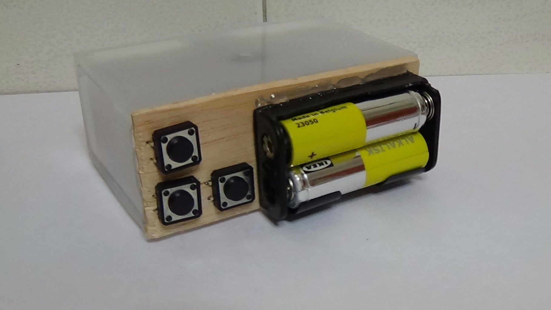
The circuit uses the ATmega328p micro controller (the same as the Arduino uno board) and the DS1302 clock IC. You can easily set/change the time by pressing the setup buttons. The clock can be activated by pressing an button or by making a sound (e.g. clap, blowing, whistle) near the microphone. It can be powered on with two AA batteries (3V) or with an USB cable from your computer (or cellphone's charger, max 5V).
Watch the presentation video below and please subscribe to our YouTube channel to help us grow up!
Official project page:http://www.ardumotive.com/7-seg-clock-en.html
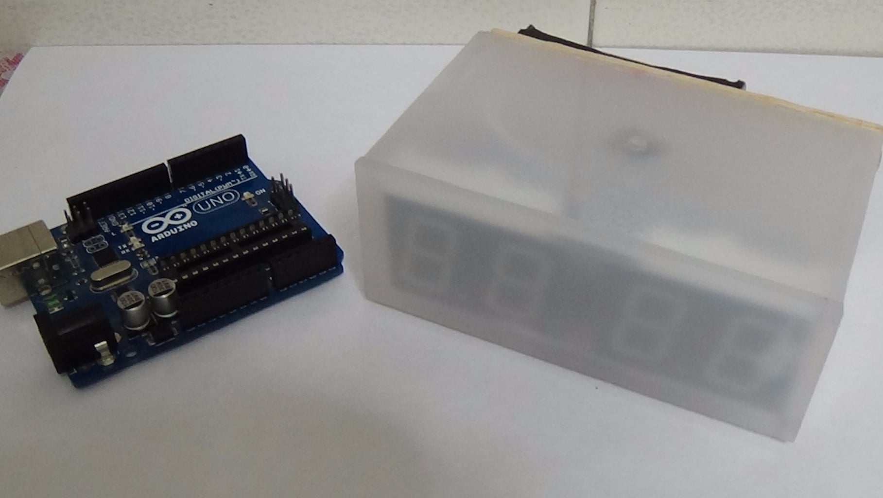
Tip: You can also use the Arduino uno board (or any other board)
Let's get started!
Step 1: What You Will Need


Visit and buy your hardware from www.gearbest.com.
For the circuit you will need:
- ATmega328p (with Arduino Bootloader)*
- 28 pin DIP IC Socket
- 4x 7 Segment Digits
- 16MHz Crystal Oscillator
- 2x 22pF and 1x 100nF capacitors
- 10K and 120 Ohm resistors
- 2 red LEDs
- 3x push buttons
- DS1302 clock IC (you can also find a module board)**
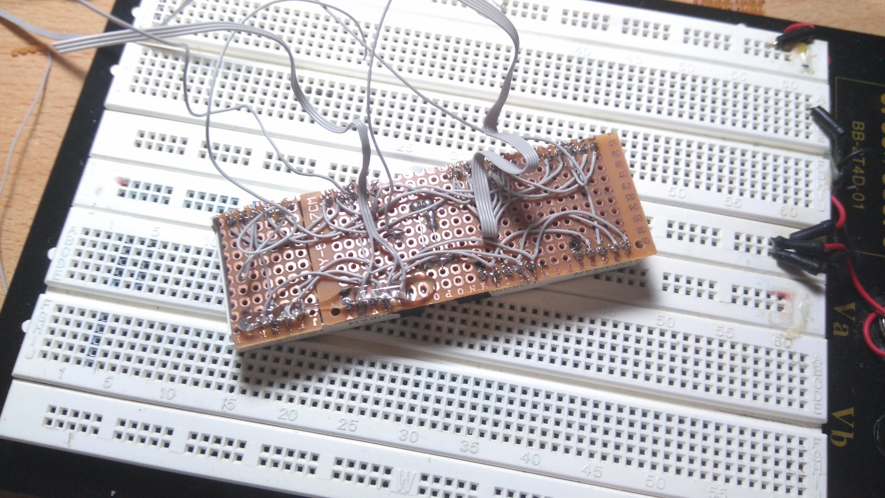
- Prototyping PCB Circuit Board Stripboard
*You will also need an Arduino UNO board to program the ATmega328 micro controller.
**You will also need a small 'button' battery 3.3V and an 32786KHz crystal oscillator. The time circuit with the DS1302 IC can be also found as a module board.
I used plexiglass pieces to build my clock box.
Step 2: The Circuit

The connections are easy, see the image above with the breadboard circuit schematic.
I made it as simple I can...
Buttons:
- Select/Set function button to Arduino pin A0
- Change time/min function button to Arduino pin A1
- Show time button to Arduino pin A2
Microphone:
- Mic goes to Arduino pin A3
DS1302:
- CE pin to Arduino pin 0
- I/O pin to Arduino pin 1
- SCLK pin to Arduino pin 2
LEDs:
- Two red LEDs to Arduino pin A4
7 segment displays:
Connect the same letters of 7 seg digits pins with others
- 1 - "E" - Arduino pin 6
- 2 - "D" - Arduino pin 7
- 4 - "C" - Arduino pin 8
- 6 - "B" - Arduino pin 12
- 7 - "A" - Arduino pin 11
- 9 - "F" - Arduino pin 10
- 10 - "G" - Arduino pin 9
Common cathode pins:
- 1st digit CC pins to Arduino pin 3
- 2st digit CC pins to Arduino pin 4
- 3rd digit CC pins to Arduino pin 5
- 4th digit CC pins to Arduino pin 13
------------------------------------------
Tip: Make your circuit on breadboard first ;)
Step 3: The Code

Here is the code, embedded using Codebender!
Codebender is an online Arduino IDE - It's the easiest way to program your Arduino board directly from your browser! Just click on the "Run on Arduino" button and that's it! Try it! It's really amazing!
You can also press the 'Edit' button and start making your modification in the sketch.
If you have any problems with sound activation feature change the values 660 and 750 (line 127):
if ((digitalRead(showBT) == LOW) || (sound<660 || sound>750))
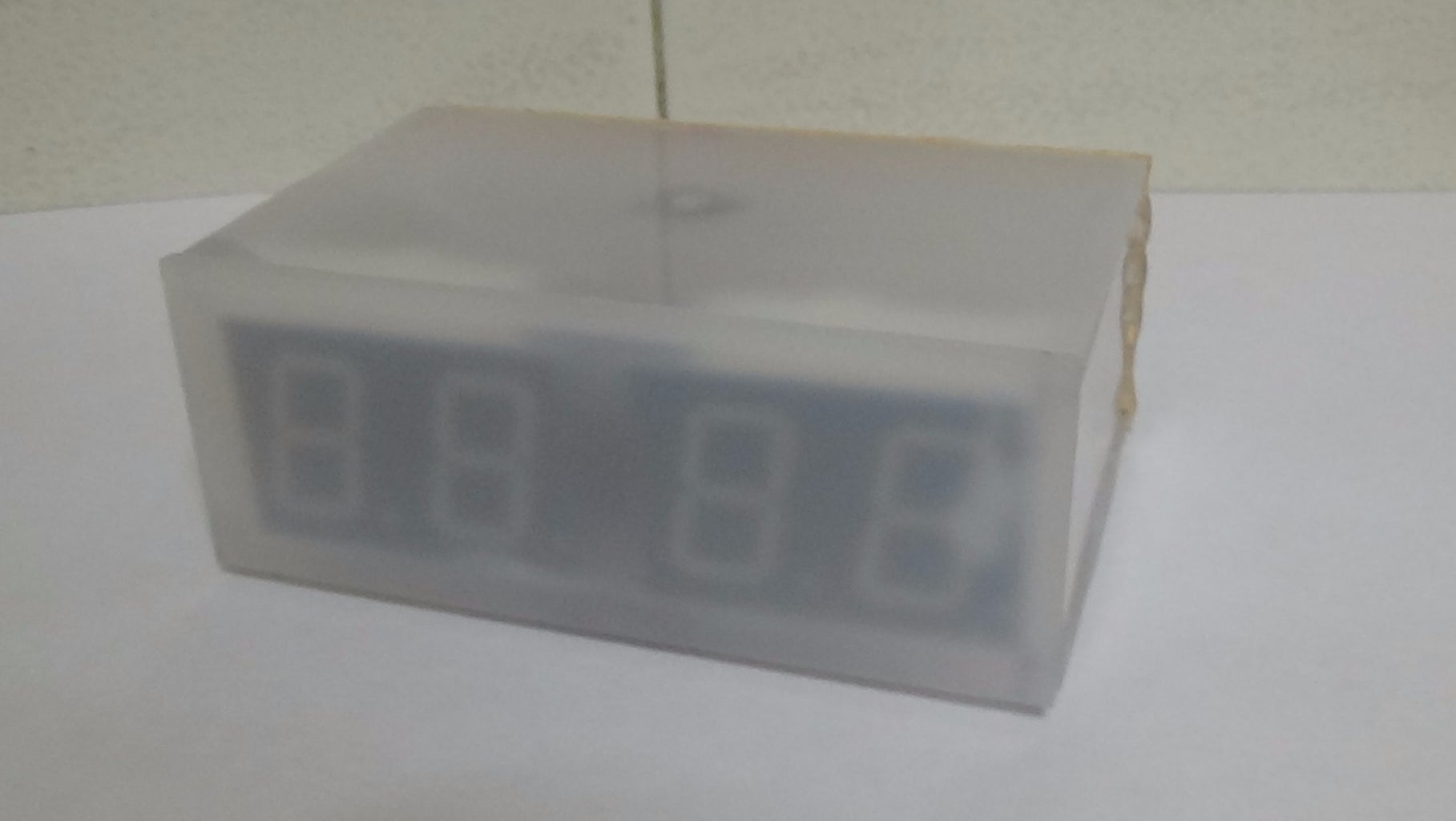
Step 4: The Box


I used plexiglass pieces to build my clock box.
Step 5: Well Done!


You have successfully completed this guide and now you have your own Arduino clock with sound activation feature in your desk!
I hope you liked this, let me know in the comments!
I would like to see photos of your cool clock ;)

Participated in the
Arduino All The Things! Contest

Participated in the
Make It Glow! Contest


