Arduino Frequency Detection by amandaghassaei
Featured
main.jpg
IMG_0041 copy.jpg
As a follow up to the Arduino Audio Input tutorial that I posted last week, I wrote a sketch which analyzes a signal coming into the Arduino's analog input and determines the frequency.  The code uses a sampling rate of 38.5kHz and is generalized for arbitrary waveshapes.  I've also turned the LED attached to pin 13 into a clipping indicator, so you know if you need to adjust your signal's amplitude as you send it into the Arduino.

Some project ideas for the code presented here include:

pitch reactive projects- change the color of RGB LEDs with pitch, or make a lock that only opens when you sing a certain pitch or melody
audio to MIDI conversion- get the Arduino to translate an incoming signal into a series of MIDI messages. See my instructable about getting the Arduino to send and receive MIDI for lots of example code to get started
audio effects- use the frequency information to reconstruct an audio signal from the tone() library or with some stored samples to make a cool effects box/synthesizer

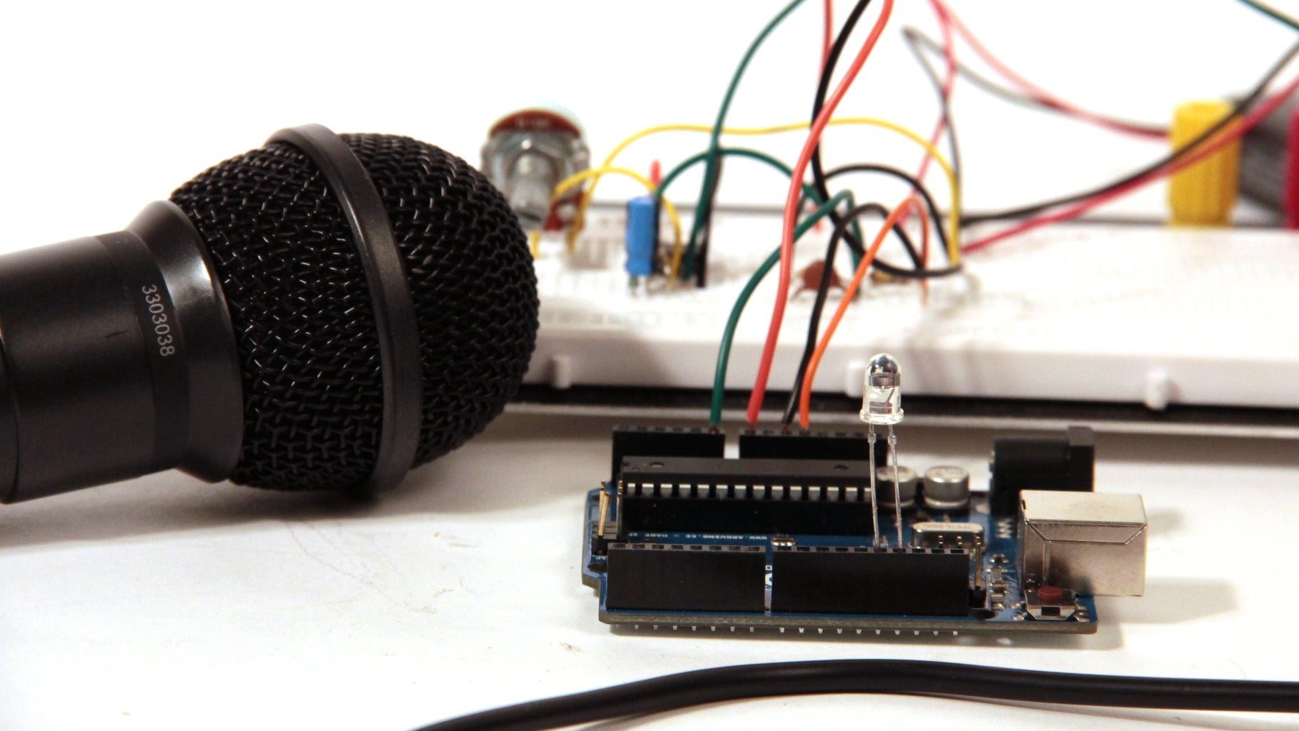
The first step of this project is to set up the audio input circuit.  I wrote a detailed Instructable about that here.

Step 1: Detection of Signal Slope

First I wanted to experiment with peak detection, so I wrote a piece of code (below) that outputs a high signal when the incoming audio signal has a positive slope, and outputs a low signal when the incoming audio signal has a negative slope.  For a simple sine wave, this will generate a pulse signal with the same frequency as the sine wave and a duty cycle of 50% (a square wave).  This way, the peaks are always located where the pulse wave toggles between its high and low states.

The important portion of the code is reproduced below.  All of this code takes place in the ADC interrupt (interrupts and runs each time a new analog in value is ready from A0, more info about what interrupts are and why we use them can be found here)

  prevData = newData;//store previous value
  newData = ADCH;//get value from A0
  if (newData > prevData){//if positive slope
    PORTB |= B00010000;//set pin 12 high
  }
  else if (newData < prevData){if negative slope
    PORTB &= B11101111;//set pin 12 low
  }


I should note here that in this tutorial I use direct port manipulation to turn off and on the output pin (pin 12) of the Arduino.  I did this because port manipulation is a much faster way of addressing the Arduino's pins than the digitalWrite() command.  Since I had to put all the code above inside an interrupt routine that was going off at 38.5kHz, I needed the code to be as efficient as possible.  You can read more about port manipulation on the Arduino website, or see the comments I've written above to understand what each line does.  You'll also notice in the code below that I used some unfamiliar commands in the setup() function so that I could get the Arduino's analog input to sample at a high frequency.  More info on that can be found in my Arduino Audio Input tutorial.

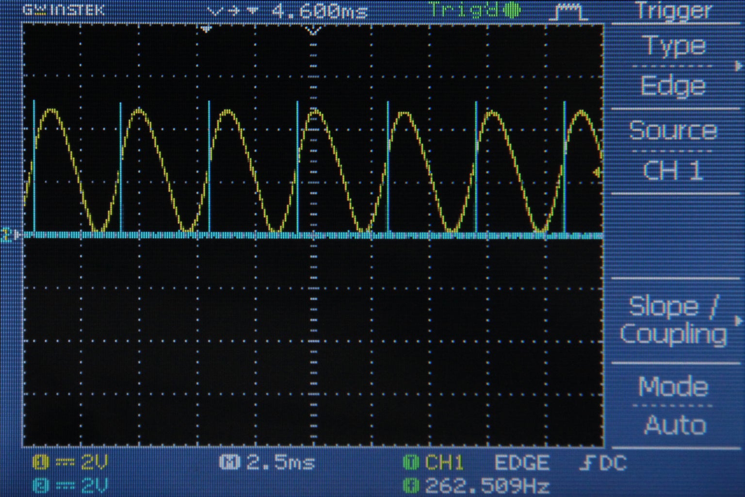
Fig 1 shows the pulse output in blue and the sine wave in yellow on an oscilloscope.  Notice how the pulse output toggles each time the sine wave reaches a maximum or minimum.  Fig 2 shows the pulse output in blue for an arbitrary waveshape in yellow.  Notice here how pulse wave takes on an irregular duty cycle because the incoming signal (yellow) is much more complicated than a sine wave.

Step 2: Mid Point Detection

I decided that I would get more accurate results detecting the frequency of a wave by keeping track of the times the wave crosses 2.5V instead of counting peaks.  In the last step I was essentially finding the places on the wave where the slope = 0 and counting the time between these events.  However, when the slope = 0, noise on the signal is enough to change the direction of the slope and skew my results.  When the wave is crossing 2.5V, it usually has a slope with a magnitude larger than 0, so I would not have to worry about the effects of noise as much.

The important changes to the code are reproduced below.  Since I am measuring the incoming signal from A0 with 8 bit precision (0-255), the midpoint (2.5V) will give a value of 127.  All of the following code takes place in the ADC interrupt (interrupts each time a new analog in value is ready from A0)

  prevData = newData;//store previous value
  newData = ADCH;//get value from A0
  if (prevData < 127 && newData >= 127){//if increasing and crossing midpoint
    PORTB |= B00010000;//set pin 12 high
  }
  else if (prevData > 127 && newData <= 127){//if decreasing and crossing midpoint
    PORTB &= B11101111;//set pin 12 low
  }


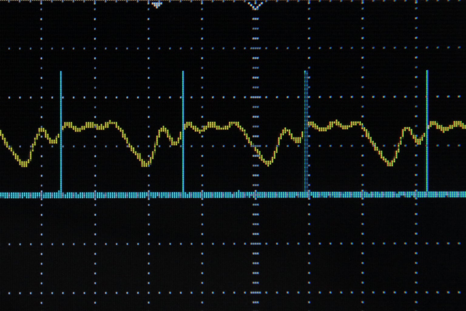
Fig 1 shows the pulse output in blue and the incoming signal to A0 in yellow.  Notice how each time the signal crosses 2.5V, the pulse output toggles.  Specifically, the output goes high when the signal crosses 2.5V with a positive slope and the signal goes low when the signal crosses 2.5V with a negative slope.  Fig 2 shows the pulse output in blue and the audio signal before it has been +2.5V DC offset in yellow.  Remember, this DC offset was necessary to get the audio signal in the 0-5V range for the Arduino's analog input pin, but normally audio signal oscillate around 0V.  In fig 2 you can see how the pulse outputs toggle corresponds to the time when the audio signal crosses 0V.  Fig 3 shows an arbitrary waveform in yellow (again before DC offset) and the pulse output in blue.  Again, the pulse toggles each time the yellow signal crosses 0V, notice how the behavior of the pulse output with the arbitrary waveform is more complex than with the sine wave.

Step 3: Sine Wave Frequency Detection

Next I measured the period of an incoming sine wave, calculated the frequency, and printed the frequency.  To do this I set up a timer in the ADC interrupt that increments each time the interrupt executes (a rate of 38462Hz).  Each time the incoming signal crosses 2.5V with a rising slope I sent the current value of the timer to a variable called "period" and reset the timer to 0.  That code is reproduced below (all takes place within the ADC interrupt).

  prevData = newData;//store previous value
  newData = ADCH;//get value from A0
  if (prevData < 127 && newData >= 127){//if increasing and crossing midpoint
    period = timer;//get period from current timer value
    timer = 0;//reset timer
  }


 timer++;//increment timer

Then in the main loop() function, I calculated the frequency by dividing the timer rate by the period.  I used Serial.print to print these results in the Arduino serial monitor.

  frequency = 38462/period;//timer rate/period
  //print results
  Serial.print(frequency);
  Serial.println(" hz");


Fig 1 shows the signal coming into A0.  The start and end of one cycle measured by timer is indicated by the image note.  Fig 2 shows the output from the serial monitor (command/ctrl+shift+m).  This technique works great for sine waves, but when wave become more complicated (and cross 2.5V more than twice in one cycle) this technique breaks down.


Step 4: Generalized pitch detection

IMG_0165 copy.jpg
IMG_0166 copy.jpg
IMG_0167 copy.jpg
IMG_0168 copy.jpg
IMG_0175 copy.jpg
Screen shot 2012-10-05 at 4.50.02 PM copy.jpg
In this code I generalized my frequency detection algorithm so that it could handle waves of many (hopefully all) shapes.  When writing this code I wanted to stick with the point I made in step 1 about not using the peaks and valleys as markers measure the period of the signal (minimize error due to noise).  I also wanted to write something that was as simple as possible (needs to execute at 38.5kHz) while still being robust enough to handle lots of waveshapes.  I decided to use a technique similar to an oscilloscope trigger.

Basically what I did was choose a voltage that I always knew would be in the bounds of my wave (2.5V).  Then I looked at every time the wave crossed this level with an upward slope, let's call these "threshold events".  If this happened multiple times in one cycle I chose the threshold event with the largest slope to be the beginning of my cycle. Similar to the last step, I used a variable called "time" (incremented at a rate of 38.5kHz) to measure the time between threshold events and stored this is an array called timer[].  I also recorded the slope at each of the threshold events in an array called slope[].  Then I compared the elements of timer[] and slope[] to figure out where there was a match.  Once a match was found, I added up the elements of timer[] to determine the duration of the cycle and sent this value to a global variable called "period."  Then in the main loop() function (all of the steps I've just described happen in the ADC interrupt routine) I used the value of period to calculate the frequency and print it.  I should also add that I put a variable in the code called "noMatch" which helped me to decide that it had been too long since I had a good match and that I should just rerecord the elements of timer[] and slope[].

When writing this I thought about a lot of possible scenarios that might break the algorithm.  The trickiest wave in my mind is one which passes the 2.5V threshold many times in one cycle at similar slopes and spaced out along the cycle similarly.  I you have a wave like this, you should keep slopeTol very low (0-3) and you might find that lowering timerTol (to 5 maybe) helps track the wave correctly.  Also, if you want to measure waves with very steep slopes (like pulse waves) you should set the value of slopeTol up to 100 or even all the way up to 256 to track them better.

Generally this piece of code seems to handle lots of shapes very well, you can see some of my results in the images above.  The incoming signal is shown in yellow and the threshold event that the Arduino is tracking is indicated by a pulse of pin 12 (blue).

I also added a bit of code to stop calculating and print frequency data when the amplitude of the wave falls below a certain level.  (If there is little or no signal then the code above sometimes spits out a bunch of garbage).  Here it is:

1-40 of 52Next »
rabidsnakemonkey says: Apr 30, 2013. 8:15 PM
This is a really cool algorithm. I would have used an fft and found the frequency with the highest amplitude, but this is much more efficient if you only want to find the fundamental frequency.
Bokononestly says: Apr 22, 2013. 1:14 PM
Great work! I'm trying to use this code for an automatic laser oscilloscope I am designing.

I've found that the code stops measuring frequencies as soon as I try analogRead() from a different analog pin. At the moment I don't fully understand the lower level programming of the ADC that you've done. Is there any way to read from the other analog pins without interfering with the pitch measurement?
amandaghassaei (author) says: Apr 22, 2013. 2:33 PM
yes, the way this is set up, all of the other analog pins are deactivated. you can read an analog value from a digital pin by using RCTime:
http://arduino.cc/en/Tutorial/RCtime
http://www.instructables.com/id/Arduino-Basics-RCtime/
hope that works for what you're doing.
contactscolored says: Apr 4, 2013. 10:49 PM
awesome!
angrycho says: Mar 30, 2013. 7:49 PM
Yeah, I ended up analyzing the whole code, and got great results. As I said, I am a beginner, so I wasn't looking to make this project the 8th wonder of the world. It ended up working great, and the device successfully tuned each string (though it took a few minutes to tune each string). I found it to be the most accurate way to tune a guitar, though not the most efficient way (because it took a few minutes to tune each string). Anyways, I want to thank you for making this instructable, because it really got me started on all of this. I ended up winning first place in my science expo with my project! Once again, thanks for making everything so simple!
amandaghassaei (author) says: Mar 31, 2013. 4:38 PM
That's great to hear! You should post and instructable about it, I think a lot of people would be interested to read about how you pulled it off
amandaghassaei (author) says: Mar 31, 2013. 4:38 PM
That's great to hear! You should post and instructable about it, I think a lot of people would be interested to read about how you pulled it off
migqc says: Mar 29, 2013. 1:51 PM
thanks for such fantastic algorithm ..

I am currently running the algorithm on a atmega16 with an external cystal at 8MHz, also i modify the code so i get that sampling at 20KHz (adc) beacuse i have an antialiasing filter of about 10KHz ...the program work nice and is fairly precise...

Now i decided to make it work on a ATMEGA128 but this time with a 11.059200MHz i set up the :

// 1 0 0 = 16 means 11MHz/16=691200Hz
//Set ADC prescalar to 16
ADCSRA |= (1 << ADPS2) | (0 << ADPS1) | (0 << ADPS0);

Also i got a delay so it exactly scans at 20KHz (adc) and on my main i have:

if(checkMaxAmp>ampThreshold)
{

frequency = 20000/period; //Timer rate divided into Period

printf("Frequency is : %u Hz\r\n",(u32)frequency);
}


Now the program doesnt work and spits a lot of ramdon frequencies...

Any ideas, do you think the the ext oscillator speed could be affecting it ??
amandaghassaei (author) says: Mar 29, 2013. 2:27 PM
it was working before for the same signal? it's possible your signal is not amplified enough. do you have an oscilloscope? have you checked the datasheet of the atmega16? there may be some differences in the ADC setup.
mbernal says: Mar 1, 2013. 11:18 PM
How can we check the wave form from the Arduino? Is it at the output pin 12 and the other one is connected to the ground? Thanks :)
amandaghassaei (author) says: Mar 28, 2013. 11:03 PM
yes if you hook pin 12 and ground up to an oscilloscope you will see the output form the arduino
angrycho says: Feb 24, 2013. 9:25 AM
This is a great instructable, but I just have a few questions. I want to start by saying that I am new to arduino, and I am working on a project to make an automatic guitar tuner. I wanted to know which variable in this program is the frequency. The desired frequency for the low string of a guitar (standard tuning) is 82 Hz.I want to say:
if the current frequency of the wave is less than 82Hz, then the servo motor will spin _ degrees counter clockwise, and if it is more than 82Hz then the servo will spin _degrees clockwise. I can fine tune the code, but I need this to start (and I can't make this code) --Thanks
amandaghassaei (author) says: Mar 28, 2013. 11:02 PM
sounds really cool, the variable "frequency" is the one you want, it is in hz.
djohansen2 says: Jan 30, 2013. 8:34 PM
Thanks for putting this together! I am a brand new and pretty unknowledgeable Arduinist and I was able to follow your "Aduio Input Circuit" instructable as well as this one. Pitch detection is something I wanted to do from day one of getting my board (2 weeks ago).

I want to use this to create an audio password - i.e. when a sequence of pitches are heard, an action takes place. I don't know exactly how to implement that type of code, but I'm going to give it a shot!

I look forward to learning more about Arduino and instructables!
amandaghassaei (author) says: Feb 4, 2013. 11:05 PM
that sounds cool! keep me posted as the project progresses/if you have any questions!
JensonBut says: Jan 25, 2013. 11:37 PM
Woo Hoo! Thanks, author!
thone says: Dec 18, 2012. 8:46 PM
Made the Instructable. http://www.instructables.com/id/Arduino-Powered-Musical-Christmas-Lights/
thone says: Dec 17, 2012. 12:29 PM
I just tried to reply to the comment but it wouldn't recognize the captcha so I had to just put a new comment.
thone says: Dec 16, 2012. 8:00 PM
I am fairly new to Instructables so I will have to take a look at putting it together. I definitely want to get a video up. I'll let you know when I get either up. (I tried replying but the captcha thing seems messed up)
amandaghassaei (author) says: Dec 17, 2012. 2:03 AM
you tried replying with a video?
thone says: Dec 15, 2012. 4:53 PM
I borrowed some of the frequency detection code you have, added a few things, moved the frequency calculation to the interrupt and was able to make some musical Christmas lights. Thanks for this awesome tutorial!
amandaghassaei (author) says: Dec 16, 2012. 12:17 AM
whoa, sounds awesome! will you post the project? or at least a video? I'd love to see it
daveclark5 says: Nov 26, 2012. 5:53 PM
very nicely written. i'll definitely check out your other midi stuff too. you've made some impressive inroads there.

i wonder what would have to be done to use this as an oscilloscope for +- 50v. A friend of mine uses audacity with some limiting circuitry on the line-in input on a sound card.
Harrymatic says: Nov 14, 2012. 1:39 PM
This is a really great project - what is the highest frequency it can measure?
amandaghassaei (author) says: Nov 14, 2012. 2:06 PM
thanks! the sampling rate is 38.5kHz, so the highest frequency it can measure would be half that, about 20khz
AntzyP says: Oct 29, 2012. 12:50 AM
Can this be used to make a guitar tuner? We can check for the frequency being played through the mic and display how near of far we are from the nearest note frequency...
amandaghassaei (author) says: Oct 29, 2012. 12:52 AM
yes, definitely. Let me know if you build it!
chaoticandrandom says: Oct 13, 2012. 2:39 PM
Nice Instructable!

There are some really good things for people to learn here especially the problem of triggering which you cover with your version of the scope trigger. Its quite hard to get over that trigger ambiguity.

However the fixed crossing reference of 2.5V you measure around can be made flexible by creating a calculated imaginary reference by just continually adding the ADC output values. So for a sine wave all the positive values and negative values will sum close or very near to zero. The same works for a square wave however the imaginary reference will now run somewhere through the center of the square wave as if someone had drawn a horizontal line on you scope screen (i.e not around zero but some positive value). The trigger will now follow around an evolved reference over time. Not sure about a triangular wave...

Hopefully it might even fit in the code?


amandaghassaei (author) says: Oct 16, 2012. 11:25 AM
interesting idea, what advantages do you think this would offer?
chaoticandrandom says: Oct 16, 2012. 12:54 PM
I believe to get good frequency detection you need to have your trigger at the fastest point of wave. By that i mean for a sine wave where the slew rate is at its maximum is around where it crosses zero. So by having the imaginary horizontal reference line as your trigger point you should get the best trigger for a sine wave. For a pulse its probably the same but for triangular i don't know. It still won't fix every dodgy trigger, it will just improve your chance of hitting the fastest point of the wave and avoiding them. Those were my only thoughts about it , hope it helps.
amandaghassaei (author) says: Oct 16, 2012. 1:20 PM
yes I thought about this, but like you I was worried about how it would handle triangle/saw waves, so I chose to compare to a set reference voltage (for me this was 2.5) and just find the max slew for the wave at this reference.
thanks for the comments!
VK5OI says: Oct 11, 2012. 2:32 PM
Thanks amandaghassaei, I'm still quite new to Arduino and programming in general (and a bit of a dumbass) but your very well written instrucable is really easy to understand and useful. Thanks for the great work.
amandaghassaei (author) says: Oct 11, 2012. 2:41 PM
thanks, glad to hear it! hope to see you post an Arduino project soon!
VK5OI says: Oct 11, 2012. 8:49 PM
I hope to soon, I quickly threw together a network diagnostic tool that literally saved me a ton of trouble at work recently. It's really handy, but the code consists of about 5 different sketches that I load depending on what I need it to do. I hope to put it all together and publish it, I think a lot of people who setup PLC networks etc (like me) will llike it.
DIY-Guy says: Oct 11, 2012. 8:24 PM
Amanda, my $.02 worth- WOW! This hot stuff! Thanks for creating this 'ible.
amandaghassaei (author) says: Oct 11, 2012. 8:29 PM
thanks for the comment!
crobson1 says: Oct 11, 2012. 10:43 AM
Will this only peak detect for positive voltages? Or will it also detect the parts of a sine wave that are negative? In other words, will it work if the waveform is centred about zero?
amandaghassaei (author) says: Oct 11, 2012. 10:54 AM
all of these waveforms are centered around 0V, but they have all been dc offset by 2.5V so that they can be read by an Arduino (only allows 0-5V in analog inputs). So the points that I was tracking on the wave actually correspond to the unbiased wave crossing 0V. does that make sense?
crobson1 says: Oct 11, 2012. 11:16 AM
That makes sense, so essentially you're tracking around inflection points? Very cool.
amandaghassaei (author) says: Oct 11, 2012. 11:21 AM
well, not quite, I'm tracking the parts of the wave that cross 0V, it's about position, not slope/derivatives, I thought about using inflection points, but triangle/saw waves wouldn't work well with this technique.
1-40 of 52Next »
Pro

Get More Out of Instructables

Already have an Account?

close

PDF Downloads
As a Pro member, you will gain access to download any Instructable in the PDF format. You also have the ability to customize your PDF download.

Upgrade to Pro today!