

Introduction: Arduino LED Watch


This instructable will show you how to make your own arduino based watch that tells time using a matrix of LEDs. This is my first instructable, so if something is unclear leave me a comment or send a message!
I was inspired by all the cool LED watches that I saw on this website:
http://www.tokyoflash.com/en/watches/1/
They have a lot of different designs that let you tell the time in very unique ways. So, I thought I'd try my hand at making my own LED watch using an arduino.
My watch design is very basic, but can be easily modified to create different LED layouts and different programming schemes. I am fairly new to arduino programming so for this instructable I will be using a modified code that I got from the Makerbot Watch project:
http://wiki.makerbot.com/makerbot-watch
I had big issues with the battery life of my first watch design, but with the modified Makerbot code and a larger battery, the watch will tell the time for at least 12 hours on a single charge. I am working on modifying the code to allow the watch to only display the time when you press one of the buttons. This should greatly increase the battery life. I will post it as soon as its finished.
***3D PRINTED ENCLOSURE***************************************
I designed an enclosure and uploaded the stl files to thingiverse. You can find all the files here:
http://www.thingiverse.com/thing:1666100
Follow the instructions in the thing summary. Happy Printing!
**************************************************************************
NOTE:
This instructable requires the soldering of very small surface mount components. If you are new to soldering, or have never handled surface mount parts before, I will try to explain as best I can how to successfully solder this project together.
Step 1: LED Matrix


This watch will tell time using a total of 28 (output) LEDs, and be controlled by 3 (input) tact switches. Obviously, an ATmega328p does not have that many programmable I/O pins so some manipulation needs to be done to individually control all those LEDs. The buttons will be controlled by 3 individual pins.
To do this, we will use a technique called charlieplexing, or display multiplexing. Basically, this method will allow us to use X number of pins to control X*(X-1) number of LEDs. For example, we can control 6 LEDs with only 3 output pins. This is possible by utilizing the tri-state logic properties of microcontrollers and the forward bias of LEDs. In other words, each pin can be set in 1 of 3 states: High (5 or 3.3V), Low (GND), or Not Connected (a high impedance state that disconnects the pin from the circuit). Also, an LED will only light up and pass current to the rest of the circuit in one direction (from anode to cathode). The first four images will give an example of how charlieplexing works using 3 pins and 6 LED's.
Now, by expanding this basic layout we can create a matrix of 28 LED's that can be controlled by a total of 11 output pins.
This is a relatively simple explanation of a complex process. If you would like more information, I found this instructable to be more comprehensive, and very well written.
Step 2: Schematic, Board Layout, and BOM


SCHEMATIC:
Now that we have the LED matrix established, we can connect it to an arduino circuit.
The watch will also have 3 push buttons used for programming and any other watch functions.
In addition, a Li-polymer battery charging circuit will be built into the PCB to allow for easy recharging of the battery. I made the schematic based off the Makerbot watch project schematic. However, I did not include breakout pads for programming, omitted the AM/PM LEDs, and omitted the alarm buzzer. I added an indicator LED for the battery charger and used different components.
BOARD LAYOUT:
WARNING!!!
Like I mentioned in the introduction, this instructable will involve a lot of surface mount soldering of very small components. I decided on these small components to keep the overall size of the watch to a minimum. However, you can easily modify the attached Eagle files (or start your own from scratch) to accommodate larger components.
The board layout I chose was fairly basic and made reading the time very easy. Eventually, I would like to arrange the LEDs in more complex layouts to make reading the time more interesting. But for now, this suited me well as a prototype for my future watches.
I wanted to keep the board size to a minimum, but was restricted by the size of the battery I planned on using. Overall the dimensions are 3.5mm by 3mm. Board size was also the reason I chose to use such small components. In addition, I did not include breakout pins for programming the microcontroller. These would take up some space and I just did not like the aesthetics of the extra pads on the board. But don't worry, it is still possible to program the chip and I will show you how later on.
Personally, I like to show off as many electrical components on the face of my PCBs because I just think it looks cool :) So the majority of the components are on the top face.
BILL OF MATERIALS:
10 PCBs from Seeedstudio are $10 plus shipping. The components needed to populate one board are about $11. The final BOM is attached in an excel file at the bottom of the page.
Attachments

Step 3: Making the PCB


Ok, for this step you can try to make the PCB yourself or have it made by a board house. I have done both and will leave the handmade version for another instructable (if people express enough interest). Lets just say, making the board by hand is very involved and time consuming, but it is possible! I used the toner transfer method and small drill bits to make the vias. (See the last image on this page)
Anyway, if you want to take the easy way out and have it manufactured, I used Seeedstudio's fusion PCB services:
http://www.seeedstudio.com/depot/fusion-pcb-service-p-835.html
This is a great PCB service. Its low cost, good quality, and the turnaround time is very fast. It took about two and a half weeks from the day I sent them my Gerber files to the time I received them in the mail. For the size of these boards, you can get 10 made for $10 plus about $5 for shipping.
My Eagle files already meet their design criteria, so just follow the instructions on the Seeedstudio page (or any other board house page), generate the gerber files and send them to order your boards. Seeedstudio will have you put your order confirmation number on the silkscreen layer of you boards. Hence, I cannot upload the Gerber files for you to download here.
If you decide to modify my design, you will need to download the Eagle design criteria on the fusion PCB page and place it into Eagle's dru folder. If you use another board house, they should have a similar file. I have attached the seeeduino fusion PCB design rules file at the bottom. Just download it, and drag it into Eagle's dru folder. Restart Eagle if you already have it open.
Once its in the folder, from your board file window, click on the design rule check button on the toolbar. (its near the big yellow exclamation point) Next, click on load and open the file you just put in that folder. This file will have all the requirements and design rules required by the board house in order for them to manufacture your board. Click on Check to see if your board meets all the rules. If not, a window will pop up telling you what needs to be changed.
Usually you will have errors in trace thickness and/or spacing. To fix this, just delete the trace and use a thicker line or move a trace to give better separation. Once everything checks out, you can generate the gerber files to be sent off to the board house.
***Like I mentioned before, Seedstudio requires that you include your order number in one of the silkscreen layers. To do this, click on the Text box in the toolbar. Select the appropriate layer, either tSilk (for the top silk layer) or bSilk (for the bottom silk layer. Type in your number and place it wherever you want. As you can see, I chose the bottom corners
TO GENERATE GERBERS:
-Usually the board house that you choose to use will have a file that you can download to generate gerber files. I actually found the one from Seeedstudio to be difficult to use, so I decided to use one that I downloaded from Sparkfun. I have attached it to the bottom of this page. Just download it and place it in Eagle's cam folder.
-Once you have it placed in the folder, click the CAM button on the top toolbar of your board file window
-Select File->Open->Job. Then open the sparkfun file that you just put in your folder.
-Finally, click Process Job
This will generate several different files wherever you have your schematic and board file saved. So its best to have them all in one folder to keep them organized. Although you have a lot of files now, the only ones you will need are:
Top layer: pcbname.GTL
Bottom layer: pcbname.GBL
Solder Stop Mask top: pcbname.GTS
Solder Stop Mask Bottom pcbname.GBS
Silk Top: pcbname.GTO
Silk Bottom pcbname.GBO
NC Drill: pcbname.TXT
Place all these files in a .zip folder and send them off to the board house!
Attachments
Step 4: Add the "arduino" Parts to the Board


The next step will be to add the parts that make this an arduino compatible board.
COMPONENTS:
-ATmega328p chip
-18pf caps x2
-16 MHz crystal
-10Kohm resistor
TOOLS:
-Fine tip soldering iron
-Thin solder wire
-De-soldering braid
-Fine tipped tweezers
-Precision screwdriver
PROCEDURE:
Surface mount soldering is not as difficult as it seems, it just takes a steady hand and a good soldering iron. If you are a novice to soldering, you may have a hard time. Follow the images below to successfully solder the components.
Step 5: Program the Arduino Bootloader


Ok, now we need to program the chip with the arduino bootloader.
I know that I did not add breakout pins on the board. I chose not to do this for aesthetic reasons and for board size restrictions. What you have to to is either solder onto the pins of the chip, or onto a pad that connects to one of the programming pins. But, if you would like to add breakout pins to the board, feel free to modify the Eagle files.
For this you will need:
-ISP programming cable. (I used ribbon cable wire)
-ISP programmer (I am using a usbtinyISP that I bought from Adafruit Industries)
You can also use your arduino as an ISP programmer. This instructable can show you how:
https://www.instructables.com/id/Turn-Your-Arduino-Into-an-ISP/
In order to program via ISP you need to connect to 6 pins on your AVR chip: (check the datasheet to know where they are on the chip)
-VCC
-GND
-MOSI
-MISO
-SCK
-RESET
In addition, the chip needs to be powered up. So, if you are using the USBtiny programmer, make sure that the 5V power jumper is in place. Once you have all your wires connected to your chip and to your programmer, load up your Arduino IDE
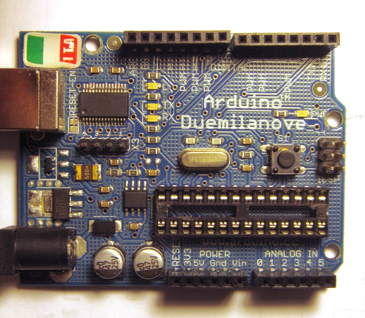
Go to Tools-> Board-> and select Arduino Duemilanove or Nano w/ Atmega328
Then go to Tools-> Burn Bootloader-> and click on the programmer that you are using. Wait about a minute and you will get a message saying "bootloarer done"
I found that getting a usbtinyISP from Adafruit was a very good investment. It works with all AVRs and is extremely easy to use. I had no problems using it to program the bootloader for this project.
That being said, I do have some experience using my arduino as an ISP programmer. It is possible to program the bootloader for this project but do not expect to get it right on the first try. Maybe not even the next few tries. If you need any help, just ask me.
Now that the bootloader is on the chip, you can de-solder all the programming wires and set them aside.
Step 6: Solder the Remaining Top Side Components


Now we will need to solder all the LEDs and resistors on the top side of the board.
COMPONENTS:
-LEDs 1-12 (Green)
-LEDs 13-24 (Red)
-LEDs 25-28 (Yellow)
-R3-R8- 330ohm
-R9-R11- 10Kohm
TOOLS:
-Fine tip soldering iron
-Soldering flux
-Solder
-Fine tip tweezers
Optional, but recommended:
-Desoldering braid
-Magnifying Glass
So, this step will require a steady hand and a lot of patience.
PROCEDURE:
If you were able to solder and program the Atmega328 chip, you should have no problem soldering the rest of the surface mount parts.
Follow the images below to solder the components
Pay attention to the order of the LED's when soldering them.
The resistors can be placed in any direction.
Step 7: Program the Board


Now that all the top components are soldered in place, its time to upload the arduino code. Actually, you could have done this right after you programmed the bootloader, but you wouldn't be able to see the LEDs light up. You can also choose to do this after soldering the back components. But, I like soldering the programming wires on a flat surface, and the back components would unbalance the board and make it harder to do so.
That said, I will leave the soldering of the back side components for the next step.
MATERIALS/ TOOLS:
-Fine tipped soldering iron
-Solder and solder flux
-Magnet wire
-Arduino board (de-chipped) or FTDI programming board
Like before, I did not add breakout pins to connect the FTDI interface. Of course, you could have also left the ICS pins connected from programming the bootloader to upload the .hex file of the sketch using AVR dude or a similar AVR programming software. But, I like using FTDI because I can leave it connected to my arduino and more easily modify and upload a different sketch.
If you are using an arduino board to program, you will need to remove the ATmega chip. To do this, carefully pry both ends with a small flat head screwdriver. Lift the chip up slowly from both sides so as to not bend any of the pins. Once the chip is out, place it in a static proof bag (if you bought all the parts for this project already, open up one of the silver bags and put it in there) If not, an Altoids tin will work.
Whether you are using an arduino or an FTDI board, the pins you need to solder will be the same. There are 5 pins:
-VCC
-Ground
-TX
-RX
-Reset
I used magnet wire to connect to the necessary pins on the board, then soldered the other ends to a few male header pins. The pins can then be plugged into your arduino or FTDI board.
Once you have everything connected, treat it as any other arduino compatible board. Connect your arduino to your computer via USB, then open up the arduino IDE. Select your board as arduino nano w/ atmega328, select your COM Port, and your're ready to program.
PROGRAMMING:
You will first need to download the MakerbotWatch .ccp and .h files from the bottom of the page. Open your arduino library folder, create a new folder and place these files in it.
I modified the original files to accommodate the layout of my board so if you happen to already have the makerbot watch files, you will need to rename these files and change the #includes in the sketch.
Download the arduino sketch from the bottom of this page, open the arduino IDE and upload it to the watch. Once it is finished uploading, the 2 LEDs at the 12 O'clock position should light up. If you wait a minute, one of the yellow LEDs will light up. Of course, you can't program the time since the buttons have not been soldered yet, but that will come later.
If you get a programming error, use a multimeter to double check all the connections. Also, make sure that you have the TX and RX pins in the right place.
Step 8: Solder the Back Side of the Board


The last soldering we need to do is to the back side of the board.
COMPONENTS:
-J1-J3 Tact switches
-Mini USB connector
-IC2 MCP7383
-C3-C4- 4.7uF
-R12- 330ohm
-LED29 (Green)
-3.7V 240mAh LiPolymer battery. Ordered from HobbyKing for about $2 plush shipping
Just as before, use the same soldering technique that I've listed for the previous steps.
PROCEDURE:
-Flux
-Solder bead
-Place component with tweezers
-Reheat solder bead
-Solder other pads
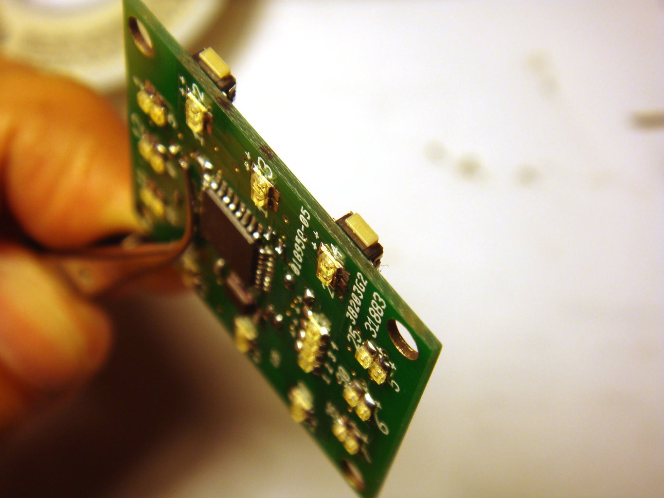
First, solder the tact switches to the board. You will need to place the body of the switches as close to flush with the edge of the board as possible. (see pictures) This will allow the actual button part to stick out and make it easier to push.
Next, solder the USB connector. Like the tact switches, try to push the connector as far off the edge as possible. This will allow for a little more room for the battery to sit later on.
Next, solder the capacitors and resistors for the battery charging circuit. The order does not matter here.
Next, solder the LED. As usual, pay attention to the orientation.
Finally, solder the battery charger IC. It has 3 pins on one side, and 2 on the other. Just match it to the pads and solder it in place,
Step 9: Test the Finished Board


Now that you have all the components soldered in place, its time to power it up and see if it works!
COMPONENTS/MATERIALS:
-Completed watch PCB
-3.7V 240mAh Li-polymer rechargeable battery. Ordered from HobbyKing for about $2 plus shipping.
-Magnet wire
-Soldering iron and solder
-Masking tape
PROCEDURE:
-Cut two pieces of magnet wire and solder them to the battery. Magnet wire is very thin and will not take up much space.
-Wrap some masking tape around the battery connections to prevent the leads from touching the PCB.
-Next, solder the positive end of the battery to the +VCC pad and the negative end to the GND pad
The battery should have a + and - labeled on it somewhere
**Be careful when using Li-polymer batteries because they can explode if punctured. They will also overheat and possibly explode if you happen to short it out.
SET THE TIME:
-Once the battery is connected, the 2 LEDs at the 12 O'clock position should light up like before.
If not, plug in a USB cable to charge the battery. The LED on the back of the board will turn off when finished charging.
-If the LEDs do light up, try programming the time:
*Press and hold the top left button for a few seconds (the LEDs will start flashing)
*Use the buttons on the right to increase or decrease the hour
*Press the top left button once to cycle to program the minute
*Use the buttons on the right to increase or decrease the minute
*Scroll through all the LEDs to make sure they are working
*Wait a few seconds for the LEDs to stop flashing
If some, or all, of your LEDs do not light up you more than likely soldered them in backwards. Or one of your components is not properly soldered in place. Still, it is possible you have a short somewhere.
TROUBLESHOOT:
The best way to troubleshoot is to make note of which LED(s) is not working, look at the schematic, and see how it is supposed to be connected. Using a multimeter, test all the connections that the LED needs to make in order for it to match the schematic.
For example, if the LED needs to connect to a resistor, touch the end of the LED and the end of the resistor with the multimeter.
When making my boards, I found that the most common mistake I made was not completely soldering all the pads on the ATMega328P chip. If this is the case for your board, use a multimeter to check the connection by touching the pad itself, and to a component it is supposed to connect to. If the continuity tester does not beep, then add more solder to the pad.
Still, there could be other problems that are harder to detect such as:
-A faulty component.
If an LED still does not light up after troubleshooting, touch the pads directly with a 2AA battery pack (or similar power supply) if the LED does not light at this point, you have a bad LED that needs to be replaced.
If you're not careful it is possible to fry your ATmega chip. These chips are pretty tough compared to other chips, but it can still happen. There really is no exact way to be sure but if you cannot upload a sketch then its a pretty good indication.
-A faulty board.
Depending on the criteria you sent to the board house that made your PCB, some of the connections could be off. This happened to me with one of the boards I ordered from Seeedstudio. When I ordered the boards, I chose a 50% E-test, so they did not perform a complete inspection of the boards after they were made. It would cost $10 more for a 100% E-test, and all the board would be in perfect working order. So it really wasn't the company's fault. But hey, 10 boards for $10 and only one mistake sounds like a good deal to me.
The error I had was with one of the vias. It was not making proper connection between the top and bottom of the board. Once I figures out what was wrong with the board, it was an easy fix.
I first used an xacto knife to scrape the top coating from both sides of the via to expose the copper pad. Then, I inserted a thin strand of wire into the hole. Finally, I soldered both ends and trimmed the excess wire. Good as new!
Step 10: Make the Watch Band


Ok, at this point you can choose to go to a watch shop and buy a any watch band you like. However, this may cause problems when trying to fit it to your case. Most watch bands connect to a watch case using a small tension rod spring, or with some type of link mechanism. Either way, the connector would need to be cut or modified to connect to the watch case you will make in the next steps. Also, I found that most replacement watch bands (the good ones anyway) are kind of expensive.
I will show you how to make an easy, inexpensive, and professional looking watch band.
MATERIALS:
-Pre-cut and pre-dyed leather wrist straps
(Hobby Lobby for about $2.50)
-A watch band buckle (22mm)
(Taken from an old watch, or purchased from a watch repair shop) (I bought mine from a mall kiosk for $3)
-Toothpick
TOOLS:
-A sharp utility blade (you may need several)
-Masking tape
-Straight edge
-Leather punch tool
(Hobby Lobby and Harbor Freight sells a descent set for around $7)
-Fabric/ Leather glue
-Clamp
PROCEDURE:
If you bought the pre-cut leather wrist band from Hobby Lobby, you could just cut it to size and glue the two sections into your case. (see picture) This is well and good, but you won't have an adjustable strap.
Here's how to make an adjustable watch band:
-First, cut off the ends of the straps to get rid of the riveted snaps. Try to cut as straight and as close to the rivets as possible to save on material. A straight 90 degree cut will save you time later on.
-Then, place masking tape on the smooth face of the leather. This will allow for easier measuring and cutting.
-Mark off a 22mm line on the masking tape. 22mm is a standard watch band size and will make it much easier for you to find a buckle that will fit.
-Using a straight edge, cut along the 22mm line you just marked.
**Save the long piece that was cut off, you will use this to make the belt loops for your watch band.
**Do not cut the 22mm piece in half just yet!!
Now comes the fun part...Skiving!!
Skiving is the process of shaving layers of leather to make the piece thinner. You will need to do this at one end of the band to accommodate the watch buckle, and for the thin piece you cut away for the band loops.
Skiving takes a little bit of practice to get the hang of, but its a fairly easy technique. Now, you could go out and buy a professional skiving tool, but I will show you how to do this with a sharp utility blade(s)
-First, wrap some masking tape to the back of the blade. This will give you a better grip and help prevent you from hurting your hand.
-You will want to skive the back, rough part of the leather piece. DO NOT SKIVE THE SMOOTH SIDE.
-If you are new to skiving, it might be a good idea to practice on a scrap piece of leather. But if you mess up, remember that the wrist straps you bought are a 2 pack :)
TECHNIQUE:
-Starting at the back of the piece, gently dig the blade into the leather. You do not want to dig too deep, just do very thin layers at a time.
-Now, slowly move the blade back and forth, while simultaneously pulling the blade towards you. You can also just directly pull the blade toward you, but I found that the side to side motion works much better.
-Repeat this process to shave off more layers.
**ALWAYS PAY ATTENTION TO HOW DEEP YOU ARE SKIVING!! If you skive too deep, you will ruin the piece.
SKIVING: (Buckle holding loop)
You will need to thin out one end of your watch band to make the loop that holds the buckle.
-First measure about 10mm from one end of your band.
-Use the skiving technique, starting at the measured line and ending at the edge of the band.
-Your goal is to thin out this end to about 1.5 mm thickness. Use calipers to check, or just eyeball it.
**If you mess up, flip the band around and start again. If you keep messing up, you always have an extra wristband to start over again.
-Once you have this section thinned out, take a toothpick and fold the end over it. Press the leather down over the toothpick to start setting the shape.
-Now, take Loop2 and place it somewhere near the toothpick between the folded section. Again, hold it in place to set the shape.
-Take a dab of fabric glue to hold the flap and loop in place. Do not get glue on the toothpick!
-Use a clamp, or something similar to hold the flap down while the glue dries. Let it dry overnight.
-Once dry, slide the toothpick out.
**Now we need to further accommodate the buckle by cutting out the slot for the prong.
-Place some masking tape over the looped end.
-Measure and mark the center line
-Mark about 2mm from each side of the center line
- Cut out that small rectangular section from the loop. Do not cut too far in! Cut the loop and a small part of the glued end.
**If you have a leather punch set, use it to punch out a rounded edge at the end of the cut.
At this point, you have a long leather strap with one looped end. Soon, you will need to cut this piece to make two sections: The part of the band with the holes, and the one with the buckle.
PLACING THE BUCKLE:
**For the buckle, you can take one off an old watch, or get one from a watch repair shop. I got mine from a mall kiosk for $3. You might need to take the band you just made so they can get you a buckle that matches it.
-The buckle will have a tension rod spring, and a prong
-To place it in your watch band, first remove the tension spring. Be careful that it doesn't fly across the room when you take it off.
-Next, place the prong in the slot that you cut out of the loop
-Slide the tension spring through the loop and through the prong.
-Place one end of the buckle onto one end of the spring.
-Using a credit card, push the other end of the spring down while simultaneously pushing on the free end of the buckle.
-The prong should be able to move freely. If it doesn't, take the buckle off and cut the slot a little more.
-Loop1 will go on this part of the band, so slide it on and set it aside.
SKIVING: (Watch band loops x2)
You will need to make two loops, one that is glued near the buckle, and one that slides freely. Here, you will be skiving the thin piece of leather you cut when making the band. Its best to skive the entire piece then cut it to size.
-Use the described skiving technique on the entire length of the piece.
-Your goal is to have an overall thickness of about 2mm.
-Once the entire piece is thinned out, you will need to cut out two pieces.
-These pieces will need to loop around two straps of leather.
To properly size the loops:
Loop 1:
-Fold over the 22mm strap, and wrap the loop around it.
-Let out a little slack, and glue the ends of the loop in place.
**This is the free sliding loop, so just set it aside for now.
Loop2:
**You will need to have skived the watch band before sizing this loop. So do that, then come back here:
-Take the loop and fold the flap over it.
-Then fold the other end of the strap over that.
-Wrap the loop around the strap
-Let out some slack, and glue the ends in place.
PROCEDURE: (cont.)
-Using your wrist and the watch case as a guide, size your band accordingly.
**You must also account for the portion of the band that will be inserted into the case and glued down. Its only a couple of millimeters, but its still something to consider.
-Cut the two pieces using a straight edge.
PUNCHING THE HOLES:
-Once again, place masking tape on the top surface of the band.
-Draw a line in the center of the tape
-Measure and mark dots that are 3mm apart. This is personal preference, you can make them closer or further apart if you like. You can also make as many holes as you like.
-If you have a leather punch tool, select a diameter hole that best fits the prong that's in your buckle.
-Go from dot to dot and punch out each hole.
That's it. You should now have one nice looking watch band.
Step 11: Make the Outer Watch Case Shell


The watch case is made with sheet and rod styrene that you can get at your local hobby shop.
MATERIALS:
-1mm thick Sheet styrene
-0.5mm thick strip styrene
-2.5mm' Rod styrene
-Tanex-7R solvent (this is made to "weld" the styrene plastic together. You can buy it at the same place you bought the styrene sheets and rods)
-Clear acrylic sheet (I bought an 8''X10" piece from Home Depot for under $3)
TOOLS:
-Hobby miter box
-Hobby fine tooth saw
You can use anything you wish to cut these pieces, but I found the above tools to work really well.
-Calipers
-Ruler
-Pen/pencil
-A good pair of scissors
-Drill bit (about 2mm diameter)
Depending on the route you chose in making the board, the dimensions for your case will vary. That said, I will describe how to build a case around your PCB as opposed to providing templates that you can just cut out.
PROCEDURE:
Get the dimensions
-First, measure the dimensions of your PCB with all the components soldered in place. You will need to know:
The Width, measured from both ends of the left and right, top buttons.
The Length, measured top to bottom
The Thickness, measured from the back of the board to the top of the ATmega328P chip (the tallest component on the top of the board) You will not need to take the USB connector or the buttons into account since the battery will sit in between them. But, if you changed the design, this may be something you need to consider.
Overall, your dimensions should be on the order of 30mm wide, 35mm long, 3mm thick
-Next, measure the thickness of the battery. This should be about 5mm.
-Finally, measure the thickness of the clear acrylic piece. It should be about 2mm thick
-The back of the case will be sealed using 1mm thick styrene.
Make the outer shell pieces (width):
Now that we know the thickness of all the parts, we need to add them up to get the overall depth of the watch case. From the above measurements, we have 5+3+2+1=11mm.
Now that we know the depth of the watch, we need to measure and cut strips of styrene to that dimension.
-First, measure and mark 11mm from the edge of the styrene sheet
-Use a straight edge and a razor blade to cut the 11mm thick strips.
-Repeat as necessary so that you have enough to make the four sides of your watch case.
Make the clear acrylic face of the watch:
Yo will need to make this piece first because we will be building around it. It will be much more difficult to glue the entire outer shell together and cutting a piece of acrylic to fit. By making the acrylic face first, you will ensure a near perfect fit.
-Start by making a rough cut at the corner of your acrylic sheet. This rough cut should be larger than the length and width dimensions that you measured earlier. You can cut acrylic like glass by first scoring with a razor blade then breaking at the score line.
-Mark the final dimensions on the acrylic. These dimensions should be the length and width measurement you made earlier, plus a few millimeters on each side to accommodate the buttons and watch band.
So it should be (PCB width from tact switch to tact switch + 4mm) by (PCB height +4mm)
-Place the flat side of the acrylic in the miter box
-Cut a straight edge using the 90 degree cutting slot and your hobby knife.
-Repeat for the other side.
Make the outer shell pieces (length):
-Place the long 11mm thick piece against the top and bottom side of the acrylic and mark the length. (The top and bottom sides are the shorter sides)
-Cut the piece in the miter box. (you will have two pieces)
-The left and right pieces will overlap the top and bottom so there is no need for exact measurements. Just cut two pieces that are longer than the acrylic.
-You now have four Pieces
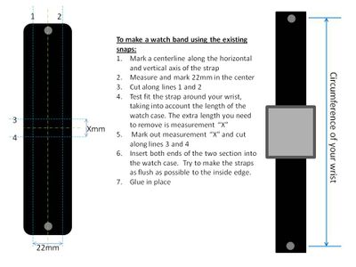
CUT OUT THE SLOTS FOR THE WATCH BAND: (the top and bottom pieces)
-Mark vertical and horizontal center lines on the top and bottom pieces
-From the measure and mark a rectangle that is the same dimension as the ends of your watch band. (see images)
-Cut out the rectangular slots using a straight edge and razor blade
-Clean up the slot with a razor blade and sand paper
DRILL OUT THE HOLES FOR THE BUTTONS, USB, and LED INDICATOR: (the two side pieces)
-First, place the completed PCB in the center of the acrylic piece and tape it down. It doesn't really have to be perfect.
-You should have some space around the PCB
-Place the side panels against the acrylic and mark the edges. Also mark the location of the buttons, LED, and USB.
-Turn the PCB/Acrylic piece on it side and measure from the bottom of the acrylic to the the center of the buttons, and USB.
-Mark this measurement on the side panels
-Drill out the holes. The button holes should be large enough to fit the 2.5mm styrene rods.
-Check the hole alignment
Make the Button sections:
-The length of the buttons does not really matter, so long as you can activate the switches from the outside of the case. I made the up and down buttons 4mm and the set button 3mm.
-Measure the desired lengths from the 90 degree cutting slot on the miter box. Place a piece of balsa wood, or similar, at the mark and secure it to the miter box with the pegs. This will allow you to slide the styrene rods against the balsa wood a let cut equal segments.
-Cut two pieces of 0.5mm styrene to make the base for the button segments. (see images)
-Place the thin pieces under the side panes and trace the holes
-Using a small paint brush, apply a small amount Tanex solvent to the circles you just traced out.
-Place the rod segments onto the circles and press for a few seconds to set the pieces
-Allow to cure for about an hour. When completely cured the joint will stronger than the original material.
WELD THE SIDE PANELS TOGETHER:
-Tape the acrylic piece to a solid surface
-Stand the top and bottom pieces against the acrylic and hold in place with poster tack.
-Apply some Tanex to the sides of the top and bottom piece and press the side panels to it. Use something square to press against the joint as it sets.
-Repeat for both sides.
-Allow to cure for several hours. Once cured, it will be as if it was molded from one solid piece.
Step 12: Make the Watch Face and Back


Now that we have the outer shell of the case, we need to make the top face and the back cover,.
MATERIALS:
-Clear acrylic piece (same one from previous step)
-3.2mm Styrenre rods
-0.5mm styrene sheets
-4 small screws. (I salvaged mine from an old cell phone)
TOOLS:
-Hobby miter box
-Hobby saw
-Small drill bit (the size of the bit should match your screws)
-Tenax-7R welding solvent
-Cyanoacrylate (CA) Glue (You can get this at a hobby shop.It sort of acts like a solvent and a super glue. But unlike super glue, it will not fog up as it dries. And unlike the Tanex solvent, it bonds to a lot more materials)
-Masking tape
MAKE THE WATCH FACE:
We will need to glue standoffs to the back of the acrylic face. They will go through the the PCB and connect to the back cover with screws.
Make the mounting posts:
-The length of the posts will be: (Width of your case) - 2mm for the acrylic top - 0.5mm for the back cover = 8.5mm (for my watch case)
-Measure 8.5mm on the miter box and secure a piece of balsa wood, or similar, at that measurement
-Place the 3.5mm diameter styrene rods into the miter box and cut iut 4 equal length pieces.
-Take a small drill bit and drill half way through each piece. The hole should be able to accept your screws.
-Insert the screws to test the fit.
Securing the posts to the acrylic:
-From the previous step, you already cut out the clear acrylic piece for the face.
-Once again, center the PCB onto the acrylic and tape in place
-Apply a small amount of CA glue to the non drilled side of the posts. Do not apply too much because unlike the solvent, the CA glue will mar the surface of the acrylic.
-Insert the posts through the PCB and press onto the acrylic.
-Let everything set to cure for about an hour before removing the PCB
MAKE THE BACK COVER:
-Place the back part of the shell onto a 0.5mm piece of sheet styrene.
-Trace the inside of the shell onto the styrene
-Cut out the piece you just traced.
-Place the back of the shell onto another piece of 0.5mm styrene
-Now, trace the outer portion of the shell onto the styrene.
-Make a rough cut around the tracing. Do not cut along the tracing, this will just be used as a guide when welding the pieces together.
-Apply some Tenax solvent to the larger piece using a paint brush. Brush a good amount inside the lines that you traced.
-Take the smaller piece and place it near the center of the traced lines. It does not have to be perfectly center.
-Allow this section to cure for a few hours. Once again, it will be as if its one molded piece.
-Now, place the completed piece into the back of the shell.
-Mark the outer edge with a pencil
-Remove the piece and cut off the excess. Sand as necessary.
SECURE THE WATCH FACE TO THE OUTER SHELL:
************IF YOU PLAN ON PAINTING THE OUTER SHELL SKIP THIS STEP UNTIL AFTER YOUR PAINT HAS DRIED***********
I will not be painting the watch for this instructable, I will leave that up to you!
-Test fit the completed watch face by inserting it into the front of the shell. Since you built the shell around the acrylic piece, it should be a near perfect fit.
-If it does not fit for some reason, try sanding the inside edge of the shell until it does.
-Remove the face and apply a thin amount of CA glue to the outer edges of the acrylic face. Again, do not apply too much since it will mar the acrylic surface.
-Carefully, place the face back into the shell.
-Allow it to cure for about an hour.
FINISH THE BACK COVER:
Now that the watch face and post are secured in place, we need to drill holes in the back cover to allow for the screws. Fortunately for us, the back cover is opaque..
-Place the back cover over the back of the shell.
-Look at it over a good light source, you will see the shadows of the posts
-Mark the locations of the posts
-Remove the back cover and drill out the holes to accommodate your screws.
-Place the cover back on to check the alignment.
Step 13: Final Assembly and Operation


At this point you should have the following components:
-Completely populated PCB
-Li-polymer battery
-Watch case
-Button sections
-Back cover
-Watch band (2 sections)
-Screws (x4)
FINAL ASSEMBLY:
-Take the two sections of your watch band and insert them into the end slots of the watch case
-Glue them in place (I used some JBquick)
-Insert the button sections. You can leave them as is, or place a little bit of CA glue in the middle of the section.
-Solder the Li-polymer battery to the back of the PCB. The two LED's at the 12 o'clock position should light up. If not, the battery may not be charged or there are some shorts on the circuit. (You might face more problems if you made the board yourself, but most are repairable)
-Insert the PCB/battery, making sure it fits onto the styrene rods. Also make sure the buttons stay in place during this step.
-Screw the back cover in place.
-That's it, you're finished!!
**Check out the last images to see my first prototype watch***
The case is made from welded aluminum. I am working on another instructable to show you how to make it.
SETTING THE TIME:
-To set the time on your watch, hold down the top left SET button for a few seconds. The LED's will start flashing when you are in Set mode.
-Use the UP/DOWN buttons on the right side to set the hour.
-Once you have the hour, press the SET button once to start setting the minutes.
-Again use the buttons on the right side to set the minute
-Once you have the minute, wait a few seconds for the LEDs to stop flashing.
READING THE TIME:
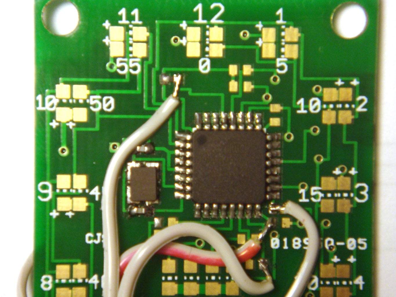
-The LEDs on the watch are arranged much like a standard 12 hour analog clock.
-The outer Green LEDs tell the hour, from 1 to 12.
-The inner Red LEDs tell the minute in 5 minute increments (0, 5, 10, 15, etc.)
-The center Yellow LED's adds minutes to the 5 minute Red LEDs from 1-4.
So if the 5 minute Red LED is lit, and 2 Yellow LEDs are lit, the total would be 7 minutes past the hour.

Participated in the
4th Epilog Challenge

Participated in the
Clocks Challenge


