

Introduction: Arduino Nano: DS1307 Real Time Clock(RTC) With Visuino


DS1307 Real Time Clock are widely available low cost I2C RTC modules. They come with a clock and a small battery, and when connected to Arduino, can keep track of real time even when the Arduino board is not powered.
In this Instructable, I will show you how easy it is to connect DS1307 I2C RTC Module to Arduino, and read the time from it with Visuino. I will use the Tiny RTC Module that I have, but it should be very much the same with any other DS1307 Module.
Step 1: Components

- One Arduino compatible board (I use Arduino Nano, because I have one, but any other will be just fine)
- One DS1307 Real Time Clock Module (I used Tiny RTC Module but any other DS1307 Module will be just fine)
- 4 Female-Female jumper wires
Step 2: Connect the Real Time Clock to Arduino

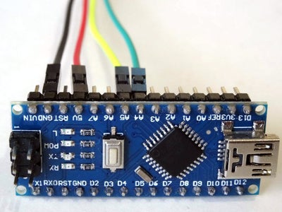
- Connect 5V VCC Power(Red wire), Ground(Black wire), SCL(Yellow wire), and SDA(Green wire), to the DS1307 RTC Module (Picture 1)
- Connect the other end of the Ground wire(Black wire) to Ground pin of the Arduino board (Picture 2)
- Connect the other end of the 5V VCC Power wire(Red wire) to the 5V power pin of the Arduino board (Picture 2)
- Connect the other end of the SDA wire(Green wire) to SDA/Analog pin 4 of the Arduino Nano board (Picture 2)
- Connect the other end of the SCL wire(Yellow wire) to SCL/Analog pin 5 of the Arduino Nano board (Picture 2)
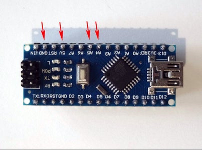
- Picture 3 shows where are the Ground, 5V Power, SDA/Analog pin 4, and SCL/Analog pin 5, pins of the Arduino Nano
Step 3: Start Visuino, and Select the Arduino Board Type


To start programming the Arduino, you will need to have the Arduino IDE installed from here: http://www.arduino.cc/.
Please be aware that there are some critical bugs in Arduino IDE 1.6.6.
Make sure that you install 1.6.7 or higher, otherwise this Instructable will not work!
The Visuino: https://www.visuino.com also needs to be installed.
Step 4: In Visuino: Add and Connect DS1307 Real Time Clock Component


- Type "rtc" in the Filter box of the Component Toolbox then select the "Real Time Clock(RTC) DS1307" component (Picture 1), and drop it in the design area
- Connect the "Control" pin of the RealTimeClock1 component (Picture 2) to the to the "In" pin of the I2C channel of the Arduino component (Picture 3)
- Connect the "Out" output pin of the RealTimeClock1 component to the "In" input pin of the "Serial[ 0 ]" channel of the Arduino component (Picture 4)
Step 5: Generate, Compile, and Upload the Arduino Code


- In Visuino, Press F9 or click on the button shown on Picture 1 to generate the Arduino code, and open the Arduino IDE
- In the Arduino IDE, click on the Upload button, to compile and upload the code (Picture 2)
Step 6: And Play...


Congratulations! You have completed the project.
Picture 1 shows the connected and powered up project.
If you open Serial Terminal in the Arduino IDE or Visuino, you will see the date and time from the Clock (Picture 2)
On Picture 3 you can see the complete Visuino diagram.
Also attached is the Visuino project, that I created for this Instructable. You can download and open it in Visuino: https://www.visuino.com


Participated in the
Raspberry Pi Contest 2016


