

Introduction: Arduino Robot V2 (Fast) Also Voice Controlled


This is my second version of my arduino robot after "Build your first robot". My Second version is slightly complicated as compared to my first one but offers better features. In this instructable I'm going to show you how to build a fast robot which can measure temperature, find things in front of it, stream videos and a lot more. With a pair of 1000RPM motors this robot can go very fast and this version uses WIFI to give a better range. This robot has two sensors on board, a ultrasonic distance sensor and a temperature sensor. The android mobile gives it additional senors to work with further more it also gives a live video stream.
The main purpose of this inscrutable is-
- Because I like posting here
- To win the sensor contest because the prizes will help me with further projects.
What upgrades have I done?
Well this is bigger than my previous version its controlled over Bluetooth but can also be switched to WIFI. This version uses 1000RPM, while my previous version uses 150RPM. With a 1000RPM my robot is capable of going over almost all terrain easily.
Update 27-04-2014
Now you can also voice control your robot, refer step 11.
Step 1: Tools and Components


Let's start with gathering is all the parts. You may want to go step-wise or you will end up running all around when you start your build.
Components
- 1x Arduino Uno R3 (or similar board)
- 1x Ultrasonic ranging module or (link)
- 1x Temperature sensor (lM35)
- 1x Bluetooth Module (HC05)
- 1x PCB
- 4x Li-ion Batery (3.7V) or (1x 12V)
- 1x L298 IC or Motor Bridge
- 4x Wheels
- 1x Switch
- Clamps, wires, screws, etc
Tools
- Soldering iron
- Multimeter
Step 2: Motor Driver (H-Bridge)


This version also uses the same H-Bridge as the previous version. You could use an H-Bridge shield instead of this, but this a cheaper alternative and works as same as the shield. This H-Bridge uses L298 IC to control the circuit.
For motor driver L298, refer the image and connect the pins as mentioned bellow.
1----Ground
2----Pin 1 of Left Side Motors
3----Pin 2 for Left Side Motors
4---- +12v battery
5---- Arduino Pin 2
6---- Arduino Pin 3
7---- Arduino Pin 4
8---- Ground
9---- +5v from Arduino
10---- Arduino Pin 5
11---- Arduino Pin 6
12---- Arduino Pin 7
13---- Pin 1 of Right Side Motors
14---- Pin 2 of Right Side Motors
15---- Ground
You could also etch a PCB if you don't want to build the circuit. I used Firtzing to build the circuit and the PCB layout, you could download the project in the attachment to modify the circuit. To the power the motors I used 4x 3.7V Li-ion batteries in series, this gives us power for both the arduino and the motors. I got the batteries from an old laptop battery pack it had 8 batteries in it.
If you mess up with the wiring the IC would get really hot. So if you have a hot IC turn off the power and check for your connections and maybe go with the PCB etching instead. If you plan to use low power motors then use l293.
Step 3: Ultrasonic Module


For the ultrasonic range module I used HC-SR04 as it is easy to find and I had it available at my house from my previous robot. The module has a maximum distance of 4m. The readings are quite precise and it has its own library. You can find the library here. Try the examples first if you are new to this. The examples are included in the library.
Connect the module-
HC-SR04 VCC pin to the Arduino
5v HC-SR04 GND pin to the Arduino GND
HC-SR04 TRG pin to the Arduino Digital pin
HC-12SR04 ECHO pin to the Arduino Digital pin 11.
Step 4: Body
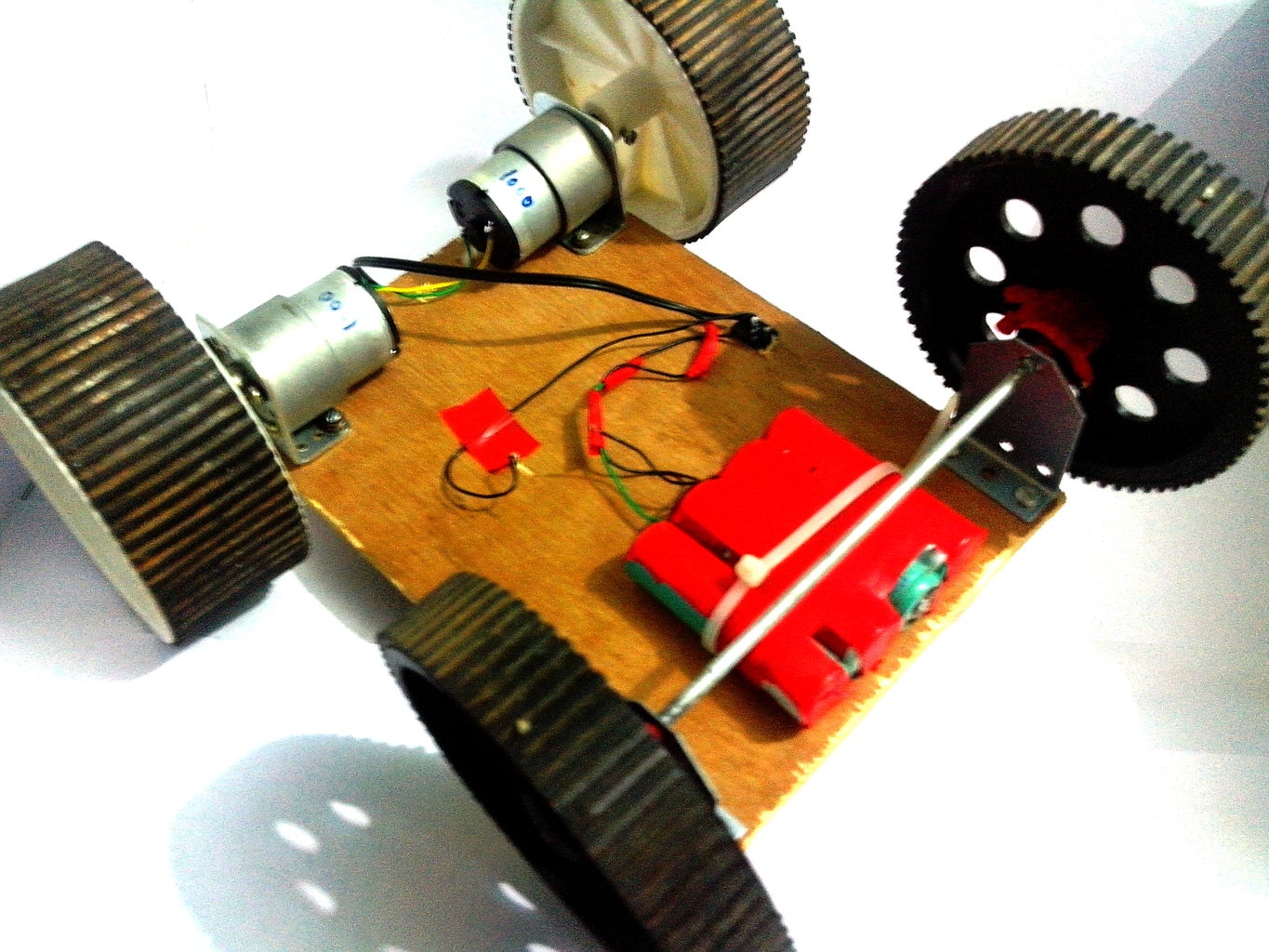

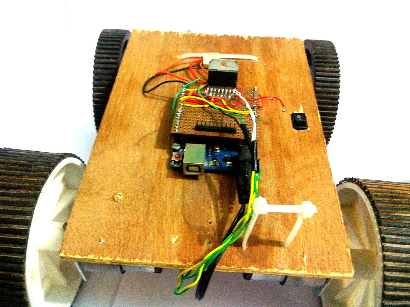
I assembled this robot on a plywood board, which I got a local hardware store. I also used clamps and shafts to hold the wheels and motors in place (also found at the local hardware store). The red coloured part just below the front heel is the Li-ion pack, I will describe about it later in the instructable. The body was not hard to assemble all you have to do is align the wheels with the board or you would have the robot going in different directions.
Step 5: Temperature Sensor

Time for the temperature sensor this is quite easy to build.
Materials
- Arduino
- LM35
Procedure
Connect the LM35 as (refer to the image for pin configuration)-
+vs to arduino 5v
Vout to arduino analog pin 0
Gnd to arduino ground
LM35 gives us an analog signal as a output so we need to convert it to digital. Which is done in the code. To check the IC (if you'r doing this for the first time) use the code at the end of this step.
float temp;
int tempPin = 0;
void setup()
{
Serial.begin(9600);
}
void loop()
{
temp = analogRead(tempPin);
temp = temp * 0.48828125;
Serial.print("TEMPRATURE = ");
Serial.print(temp);
Serial.print("*C");
Serial.println();
delay(1000);
}
Step 6: Bluetooth


For the Bluetooth module I used HC05 which is the cheapest module I could find (on EBay). The only thing with this board is that you need to create a voltage divider as the arduino gives 5V output in its Tx pin while the HC05 accepts only 3.3 so a voltage divider is required to prevent the burning out of the board.
If you want to make it simple you could buy thismodule instead which does not require any voltage divider.
Step 7: IP Camera App

For this step you could use any IP camera, but I used an android phone instead because I can add on the features of any smartphone on to my robot.
To get the app
- Visit android Play Store
- And Download the app named "IP Camera Android"
- After installing the app start a server
- After the server starts an IP will pop up below the screen
- Type the IP adress on a PC browser connected to the same network
- Enjoy the video stream
Step 8: Battery
For the battery I used 3x Li-ion I found this in an old battery pack. It had eight of this and I got five of it working. Each of the battery gives 3.7V, 1000mAh and 3 batteries gave me 15.2V when full charged. I got the charger from EBay. The Li-ion batteries are slightly larger compared to normal AAA sized battery so i could not get any battery holder for it. The battery acts a power source for both arduino and the H-bridge.
Warning
Be careful about the charging of the battery, Li-ion batteries are unstable when overcharged and have risks of exploding. Also don't discharge the battery too much, Because it is hard to bring it back to 3.7V
Step 9: Bluetooth


Now time for the controls, as I mentioned earlier it can be controlled over Bluetooth. I'm working on how to connect it to a local area network. Right now you can control it via android mobile and your laptop.
Let's control it over PC
- I used tera term to control it over PC via Bluetooth.
Let's control it over android
- Visit android Play Store
- Download the app named "Arduino Bluetooth RC Car"
- After installing the app pair with your robot
- Connect to it and enjoy controlling it
Attachments

Step 10: Code

The code can be found in the attachments. Feel free to modify the code but just leave a comment on what you came up with it.
Code
#include
Servo servoMain;
float temp;
int tempPin = 0;
int r_motor_n = 2; //PWM control Right Motor -
int r_motor_p = 4; //PWM control Right Motor +
int l_motor_p = 5; //PWM control Left Motor +
int l_motor_n = 7; //PWM control Left Motor -
int enable = 3;
int light = 9;
int enable2 = 6; //PWM CONTROL SPEED
int speed1 = 0; // PWM controll speed
int incomingByte = 0; // for incoming serial data
#include
#define TRIGGER_PIN 12 // Arduino pin tied to trigger pin on the ultrasonic sensor.
#define ECHO_PIN 11 // Arduino pin tied to echo pin on the ultrasonic sensor.
#define MAX_DISTANCE 200 // Maximum distance we want to ping for (in centimeters). Maximum sensor distance is rated at 400-500cm.
NewPing sonar(TRIGGER_PIN, ECHO_PIN, MAX_DISTANCE); // NewPing setup of pins and maximum distance.
void setup()
{
servoMain.attach(10);
pinMode(r_motor_n, OUTPUT); //Set control pins to be outputs
pinMode(r_motor_p, OUTPUT);
pinMode(l_motor_p, OUTPUT);
pinMode(l_motor_n, OUTPUT);
pinMode(enable, OUTPUT);
pinMode(enable2, OUTPUT);
pinMode(light, OUTPUT);
digitalWrite(r_motor_n, LOW); //set both motors off for start-up
digitalWrite(r_motor_p, LOW);
digitalWrite(l_motor_p, LOW);
digitalWrite(l_motor_n, LOW);
digitalWrite(enable, LOW);
digitalWrite(enable2, LOW);
digitalWrite(light, HIGH);
Serial.begin(9600);
Serial.print("Whats up im ATOM, geared up!!!! \n");
Serial.print("w = Forward \n");
Serial.print("s = Backward \n");
Serial.print("d = Right \n");
Serial.print("a = Left \n");
Serial.print("f = Stop \n");
Serial.print("lame freaks robotics");
}
void loop()
{
if (Serial.available() > 0) {
// read the incoming byte:
incomingByte = Serial.read();
}
switch(incomingByte)
{
case 'S': // control to stop the robot
digitalWrite(r_motor_n, LOW); //Set motor direction, 1 low, 2 low
digitalWrite(r_motor_p, LOW);
digitalWrite(l_motor_p, LOW);
digitalWrite(l_motor_n, LOW);
analogWrite(enable, 0);
analogWrite(enable2, 0);
Serial.println("Stop\n");
incomingByte='*';
break;
case 'R': //control for right
digitalWrite(r_motor_n, HIGH); //Set motor direction, 1 high, 2 low
digitalWrite(r_motor_p, LOW);
digitalWrite(l_motor_p, HIGH);
digitalWrite(l_motor_n, LOW);
analogWrite(enable, speed1);
analogWrite(enable2, speed1);
Serial.println("right\n");
incomingByte='*';
break;
case 'L': //control for left
digitalWrite(r_motor_n, LOW); //Set motor direction, 1 low, 2 high
digitalWrite(r_motor_p, HIGH);
digitalWrite(l_motor_p, LOW);
digitalWrite(l_motor_n, HIGH);
analogWrite(enable, speed1);
analogWrite(enable2, speed1);
Serial.println("left\n");
incomingByte='*';
break;
case 'F': //control for forward
digitalWrite(r_motor_n, HIGH); //Set motor direction, 1 high, 2 high
digitalWrite(r_motor_p, LOW);
digitalWrite(l_motor_p, LOW);
digitalWrite(l_motor_n, HIGH);
analogWrite(enable, speed1);
analogWrite(enable2, speed1);
Serial.println("forward\n");
incomingByte='*';
break;
case 'B': //control for backward
digitalWrite(r_motor_n, LOW); //Set motor direction, 1 low, 2 low
digitalWrite(r_motor_p, HIGH);
digitalWrite(l_motor_p, HIGH);
digitalWrite(l_motor_n, LOW);
analogWrite(enable, speed1);
analogWrite(enable2, speed1);
Serial.println("backwards\n");
incomingByte='*';
break;
case 'f':
digitalWrite(r_motor_n, LOW); //Set motor direction, 1 low, 2 low
digitalWrite(r_motor_p, LOW);
digitalWrite(l_motor_p, LOW);
digitalWrite(l_motor_n, LOW);
analogWrite(enable, 0);
analogWrite(enable2, 0);
Serial.println("Stop\n");
incomingByte='*';
break;
case 'd':
digitalWrite(r_motor_n, HIGH); //Set motor direction, 1 high, 2 low
digitalWrite(r_motor_p, LOW);
digitalWrite(l_motor_p, HIGH);
digitalWrite(l_motor_n, LOW);
analogWrite(enable, speed1);
analogWrite(enable2, speed1);
Serial.println("right\n");
incomingByte='*';
break;
case 'a':
digitalWrite(r_motor_n, LOW); //Set motor direction, 1 low, 2 high
digitalWrite(r_motor_p, HIGH);
digitalWrite(l_motor_p, LOW);
digitalWrite(l_motor_n, HIGH);
analogWrite(enable, speed1);
analogWrite(enable2, speed1);
Serial.println("left\n");
incomingByte='*';
break;
case 'w':
digitalWrite(r_motor_n, HIGH); //Set motor direction, 1 high, 2 high
digitalWrite(r_motor_p, LOW);
digitalWrite(l_motor_p, LOW);
digitalWrite(l_motor_n, HIGH);
analogWrite(enable, speed1);
analogWrite(enable2, speed1);
Serial.println("forward\n");
incomingByte='*';
break;
case 's':
digitalWrite(r_motor_n, LOW); //Set motor direction, 1 low, 2 low
digitalWrite(r_motor_p, HIGH);
digitalWrite(l_motor_p, HIGH);
digitalWrite(l_motor_n, LOW);
analogWrite(enable, speed1);
analogWrite(enable2, speed1);
Serial.println("backwards\n");
incomingByte='*';
break;
case 'r': // servo angles
servoMain.write(0);
break;
case 't':
servoMain.write(45);
break;
case 'y':
servoMain.write(90);
break;
case 'u':
servoMain.write(135);
break;
case 'i':
servoMain.write(180);
break;
case 'O': // PWM speed values
speed1 = 0 ;
break;
case '1':
speed1 = 155;
break;
case '2':
speed1 = 165;
break;
case '3':
speed1 = 175;
break;
case '4':
speed1 = 185;
break;
case '5':
speed1 = 195;
break;
case '6':
speed1 = 205;
break;
case '7':
speed1 = 215;
break;
case '8':
speed1 = 225;
break;
case '9':
speed1 = 235;
break;
case 'q':
speed1 = 255;
break;
case 'm':
temp = analogRead(tempPin); // Read the temperature
temp = temp * 0.48828125;
Serial.print("TEMPRATURE = ");
Serial.print(temp);
Serial.print("*C");
Serial.println();
delay(1000);
break;
case 'p': // time to ping thr ultasonic sensor
delay(50); // Wait 50ms between pings (about 20 pings/sec). 29ms should be the shortest delay between pings.
unsigned int uS = sonar.ping(); // Send ping, get ping time in microseconds (uS).
Serial.print("Ping: ");
Serial.print(uS / US_ROUNDTRIP_CM); // Convert ping time to distance in cm and print result (0 = outside set distance range)
Serial.println("cm");
break;
delay(5000);
}
}
Support me and vote, if I win I guarantee you that you would see plenty of projects like this and if you have any problems feel free to PM me.
Step 11: Voice Control

Update 27-04-2014
Now you can voice control your robot. Download my app from the attachments and install it on your android mobile. Connect the app to the robot and enjoy the new feature.
Commands
"Forward"
"Backwards"
"Right"
"Left"
"Stop"
"Speed up"
"Speed down"
And don't forget to vote for me in the contest.
Attachments

Second Prize in the
Robot Contest

Participated in the
Arduino Contest

Participated in the
Sensors Contest


