

Introduction: Arduino Self-Balance Controller Using DIGITAL IMU, at Last!


What is it?
DIY Segway/balance controller with modern DIGITAL IMU sensor.
Software for an Arduino that allows it to read position data from one of the newer DIGITAL accelerometer/gyroscope units, processes the data using Kalman Filtering (the really clever one) and then sends control signals to a motor controller allowing your machine to self-balance.
All my self balancers are also documented in my You Tube channel here:Click
Why do this? You have done a similar Instructable already:
I wrote an Instructable in 2010 describing a Segway style skateboard with two motors, two central wheels and a self balancing system using an Arduino as the "brain" and a combination of a solid state gyroscope and accelerometer as sensors of how much the machine was tilting.
The accelerometer and gyroscopes used put out a voltage from 0-5V proportional to the angle of tilt from the vertical (or in the case of the board, the level) position, but these are becoming very hard to find. These are known as analog Inertial measurement units (IMU's).
I updated the control system and tried to make it easier to build as an Arduino "shield" as a new Instructable in 2013, using an analog IMU still available from China. However, now, even this one is getting tricky to obtain.
So, finally, after quite a while trying, I have managed to get this control system to work using an Arduino and a commonly available DIGITAL IMU, from Sparkfun. This communicates with the Arduino via what is known as the I2C protocol.
I have used snippets of code from all over the web, and I hope I have credited them all at the top of the Arduino sketch, which is attached to Step 16.
Why is this a big deal?
People have been asking me for this for around 2 years now. It has not been easy.
The big deal is that I have tested it and IT WORKS ! ................ which is always useful when you are standing on the thing.
I have also more recently (December 2014) built a twin wheeled scooter inspired by the 1970's Raleigh Chopper using the same Sparkfun digital IMU: Raleigh Chopper inspired self-balancing scooter.
Read my earlier Instructables first if you need more information on the actual physical construction of devices of this kind:
The first skateboard 2010: https://www.instructables.com/id/Easy-build-self-balancing-skateboardrobotsegway-/
The updated control system 2013 using a just-about-still-available analog IMU: https://www.instructables.com/id/Self-balancing-skateboardsegwy-project-Arduino-S/
My original big website on all things self-balancing: https://sites.google.com/site/onewheeledselfbalancing/
I will flesh this Instructable out with more information as people ask me questions but I am putting it up right now as I know people have been struggling to obtain the old analog IMU's, so now they have an alternative.
Arduino code attached to step 16. Also attached to step 16 is some code that just allows you to test the IMU and Arduino are talking to each other (it displays tilt angle on your PC screen serial-view window) before you attach all the peripherals like the deadman switch, steering switch and so on (also useful as a start point for people who want to use this for something else).
A video of this "IMU Tester" code working and displaying the angle of tilt on a laptop can be watched here:
https://www.youtube.com/watch?v=wwLp6DeW5Gk&feature=youtu.be
Now I will have to remove that "ANALOG" logo from the skateboard.
Step 1: Sparkfun 6dof DIGITAL IMU SEN-10121

View of this IMU.
It is Code number SEN-10121 with Sparkfun.
They describe it as: IMU Digital Combo Board - 6 Degrees of Freedom ITG3200/ADXL345
It has 3 gyros and 3 accelerometers inside.
It communicates with the Arduino using the I2C protocol.
Note for enthusiasts for this sort of thing:
Pull-up resistors are not required as they are already present on the little red circuit board the IMU sensors are mounted on.
If you don't know what this means it does not matter at all, it just refers to various on-line debates about hooking up this kind of sensor to an Arduino.
Step 2: Sparkfun 6dof Digital IMU

Rear view showing the wiring connections.
Step 3: General Layout of a Typical Self Balancing Skateboard

Step 4: Orientation of This IMU on the Board

Obviously not to scale, this shows the orientation of the IMU relative to the surface of your skateboard or segway type machine, i.e. lie it flat like this.
Step 5: Wiring Diagram for This IMU

LED's not vital but quite helpful.
IMPORTANT NOTE 23.6.15: One person building this found that the IMU "locked up" and stopped talking to the Arduino. He solved it by making sure he used the SAME GND PIN on the Arduino for both the IMU GND wire and also the 0V wire from the Sabertooth. There are several GND pins on an Arduino Mega and they are connected to each other on the board, however he found it was more reliable if you use the same one for all your GND connections to the Arduino.
Turn machine on with one end tilted down on ground. Wait for the LED's to both come on, while pressing in the "Deadman" switch, it is now ready for you to bring it level. When level the self-balancing will turn itself on and off you go hopefully.
If power to motors is > 50% of maximum one LED will come on while riding it.
If power to motors is > 75% of maximum both LED's will come on while riding it and this is a warning for you to slow down a little.
If you let go of the deadman switch all power to the motors will be cut after a delay of 0.5 seconds (for safety).
The thing on the right is a Dimension Engineering Sabertooth 2 x 25 Amp motor power controller.
The Arduino sends serial commands to it to tell each motor how fast to go and in what direction.
The balancing software loops 100 times per second and in this way it stays level.
There are also wires to some of the digital Pins on the Arduino and these are not shown here. These are from the deadman switch, the steering rocker switch and the rocker switch that allows fine tuning of the balance point to suit each rider.
These connections from the hand controller are all listed in Step 17.
Step 6: Wiring the IMU
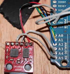
I chose to solder the wires to the Arduino from the IMU as if these connections are not good it will just not work properly.
Before anyone asks what are the extra wires on the remaining analog ports there for, I should just say I have a collection of Arduino boards now that have all been previously used in other projects. The extra wires on the analog ports 0 - 3 are there because I was too lazy to de-solder them! Please ignore them, they do nothing in this project.
Step 7: Powering the Arduino

Keeping it simple here.
Just using 6 x AA batteries and a switch.
Plenty of things to go wrong at the debugging stage so keep simple the things you can keep simple.
Step 8: Wiring Sabertooth to the Motors

Step 9: Setting Up the Sabertooth

Step 10: More on Sabertooth Wiring

Step 11: Powering the Sabertooth

Step 12: Deadman, Steering and Balance-point Adjustment Switches

I use a good quality microswitch for my deadman switch which "clicks" between 2 states, either on or off and nothing in between.
Pushbutton push-to-make switches, especially cheap hobby ones, have a mid zone if you only gently press the button of "just about unreliably on" which is totally not suitable for a machine like this. I have found this out the hard way by falling off.
The code has a variable that counts down to zero over 0.5 sec then cuts all power if you let go of the deadman switch. This means if the switch has dirty contacts, it will tolerate a disconnection lasting less than 0.5 sec without throwing you off.
Little things like this are important for a good user experience and again, I have been learned this the hard way!
Alternative for even better reliability would possibly be to use a double pole micro-switch, if such a thing exists, as deadman switch and wire the connections in parallel so if one contact is dirty and unreliable, the other will still do the job.
People often ask me how to use a potentiometer to create more proportional steering. It can be done of course but I would say keep it as simple as possible until you get your machine balancing OK with you on it, then, and only then, start worrying about other things. A rocker switch (NB: with a mid point where neither output is connected to GND) is simplest way to achieve steering. It is in fact "proportional" as machine tries to turn more, the longer the time you flick the switch left or right for.
Step 13: Hand Controller Detail View

Step 14: Libraries You Need to Download and Put in Your Arduino Libraries Folder

Download the folder "FreeSixIMU" from this website and put whole folder into your Arduino libraries folder so then the libraries listed above can be accessed by the Arduino.
Instructions on how to download this folder and put it into your Arduino libraries folder can be found here on
this website (scroll down the page about half way):
http://bildr.org/2012/03/stable-orientation-digital-imu-6dof-arduino/
Step 15: Putting "FreeSixIMU" Into Your Libraries Folder

Step 16: The CODE

A) FULL CODE:
This was written on Arduino Version 1.5
I have tried to attach it as an .ino file as used by Arduino 1.5 but Instructables will not let me upload it.
Therefore have also attached it as a text document which, if copied and pasted into a new empty Arduino sketch, should then compile OK and save OK.
B) NOTE: IMU TESTER CODE:
I have also attached a sketch (again as a text file) that allows you to wire up the IMU only, attach the Arduino via its USB cable to your computer, open the "Serial View" window (set to 9600 Baud) then play with tilting the IMU. The Angle of tilt from vertical will be displayed on the computer screen in the serial view window at half second intervals.
Zero is level, -ve values appear (in degrees of tilt from "level") if you tilt it one way and similar sized +ve values appear if you tilt it the other way. Start with your IMU flat on table with the surface mount components facing upwards.
This allows you to test the IMU and Arduino are talking to each other, before you attach everything else such as the Sabertooth, rocker switches and deadman switch.
Here is a video of the IMU tester code sending the tilt angle to the laptop screen with the Arduino serial view window open:
https://www.youtube.com/watch?v=wwLp6DeW5Gk&feature=youtu.be

Step 17: Digital Pin Listing for the Arduino
Two of the analog pins are also the pins SCL and SDA that connect to the Sparkfun IMU.
This has already been covered earlier on.
Lets now just confirm what each of the Digital Pins are connected to:
Arduino Digital (not analog) Pin What it does
2 Balance fine trim switch nose down slightly
3 Balance fine trim switch nose up slightly
4 Turn left connection on steering rocker switch
5 Turn right connection on steering rocker switch
9 Deadman switch (if you let go of this button all power to motors is cut).
Safety feature.
1 Tx (transmit) pin from Arduino to Sabertooth motor power controller.
It sends the motor power commands to the Sabertooth via a
Serial communication.
***********NOTE NOTE NOTE NOTE NOTE*************************************
NOTE: You have to UNPLUG this Digital 1 Pin from the Arduino while you load the
program (sketch) else it will not load.
Once sketch is loaded, put this pin back into its socket on the Arduino again
so it can talk to the Sabertooth.
****************************************************************************************
Note (for the experts) I could not use SoftSerial for this communication with the Sabertooth,
and so use a more convenient pin, as softserial would not work.
Not sure if running out of memory or what!
10 LED 1
11 LED 2

Participated in the
Full Spectrum Laser Contest


