

Introduction: Arduino Throttle Body Syncronization Shield


A common Motorcycle maintenance task is to synchronize the throttle bodies on the engine to smooth out any rough idle. This is done by monitoring the vacuum on each throttle body and using the idle screw to make the adjustment.
While this sounds rather advanced, with a little knowledge, a few standard tools to access the engine, and a TBS tool (Throttle Body Synchronization); the maintenance item really isn’t that hard.
Now you can buy a tool or build a TBS tool using fluids and tubes (there are examples of this out there on the interwebs), but I wanted to use an Arduino and some electronics to build my own to do the job. This instructable describes my journey in making my own Arduino Throttle Body Synchronization shield.
Step 1: Research
A TBS tool is rather simple in what it does; it will measure the vacuum that each cylinder is actively producing when the engine is running. To measure vacuum with an Arduino I needed to build a shield that would contain a vacuum sensor for each cylinder on my engine (4 in my case).
There are many vacuum sensors available from your favorite electronics parts stores. The interesting range that I need to measure is around -33 kPa (-4.78 psi). This is the value that should be measured on my motorcycle on a single cylinder when the engine is warm and at idle. You should consult a service manual for the specifics for your engine. So I picked one that measured a range between 0 kPa to -50 kPa.
Then I needed to understand how to connect this to my engine. The service manual helps here also, but I also found many great write ups on the web. I just needed some standard engine vacuum hose with an inner diameter of 1/8th inch which will push onto a service nipple already present on the throttle body. This same hose will directly push onto the vacuum sensor. I found this in bulk at my local automotive store. I needed four hoses each with at least 3 feet length so I could put the Arduino and sensors in a safe place.
Step 2: Designing the Shield


The sensor I picked required a pretty simple schematic. It just needed three capacitors. Further, providing that it got 5v to run on it would provide an analog voltage that represented the vacuum reading in the range of 4.6v ( at 0 kPa) to 0.1v (-50 kPa). This is great for connecting directly to the Arduino analog input pins.
I used the free version of Eagle to design the first sensor schematic. Eagle is a PCB design software that is commonly used by many hobbyist to design schematics and layouts for circuit boards. There are many videos and instructions on how to use Eagle, and like all moderately complex software it just takes a little time using it to become familiar with how it works.
Then all I had to do was replicate the schematic for a single sensor four times and add the connector for pushing the shield onto the Arduino.
With the schematic complete, I switched to board layout mode and followed some other shield layouts to build an outline that would simply press onto an Arduino like all shields do. I finished it by then placing all the parts and running all the trace lines.
Once I had the completed design and layout, I did research and found a company that did PCB prototype creation. They accepted Eagle files directly, making it easy to upload, pick the number I wanted, and submit my order. I then just needed to wait for my boards to be shipped to me.
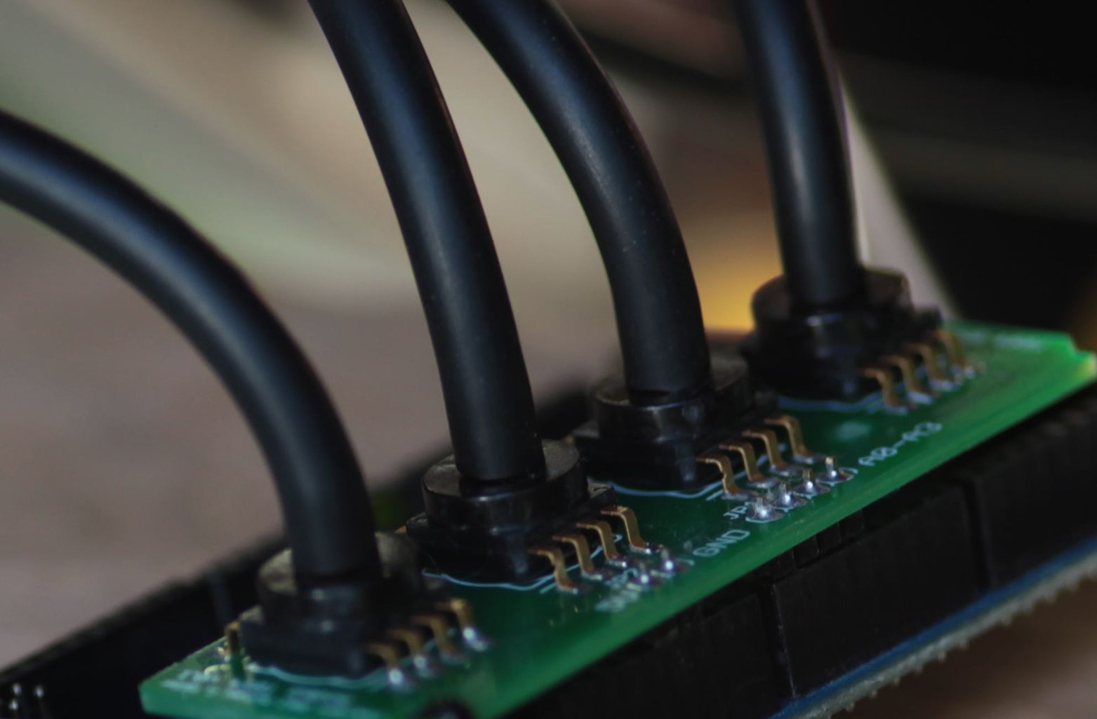
Step 3: Assembling the Shield


(4) vacuum sensors MPXV5050VC6T1CT-ND
(4) 470.0 pf ceramic capacitors (surface mount 0603) 478-6201-1-ND
(4) 0.01 uf ceramic capacitors(surface mount 0603) 445-5100-1-ND
(4) 1.0 uf cermic capacitors(surface mount 0603) 311-1445-1-ND
I suggest a good quality soldering iron when soldering surface mount parts by hand. There are many techniques to soldering surface mount parts, some are better when you have a lot of soldering to do; but I just do it by hand. Again, searching the interwebs will give you lots of ideas. While a fine tip on the soldering iron is not a requirement, I found that a flat tip that wasn’t too large was very helpful. Also use fine high quality solder.
Having a solder helper is also very handy. Mine has multiple alligator clips to pinch the board in and they can rotate to hold the board flat. Further, mine also has a tray in the base to hold the solder spool.
I found having some sort of vision enhancement was a requirement. While my vision is still very good, I could not imagine soldering such small parts without some magnification. I found using reading glasses with a decent magnification works really well. I only lost two capacitors out of the 12 I had to solder in. They were close to the size of a grain of sand. Next time I will use larger SM parts.
I applied a little solder flux liquid (comes in a bottle) to each SM pad and a little between. This stuff is sticky and helps hold the part to the board while you solder. Then I lightly press the soldering iron to one side while being careful not to move the part. I then hold some solder to what little of the pad that is left showing next to the part lead, and it will just flow around the pad and lead. Let it cool for 15 seconds and then repeat for the other leads.
Once complete, I used some alcohol and a Q-Tip to wash away any left over solder flux to clean up the board.
Step 4: Writing Some Software

My software came in two parts. One part ran on the Arduino and collected the ADC values, filtered them, and sent the summary out the serial port. The second part ran on the PC and listened for the data from Arduino and provided a nice UI to visualize the results.
On the Arduino, I just needed to read the ADC pins to get values, and then convert these into kPa.
Int Sample1 = analogRead(A0);
Int Sample2 = analogRead(A1);
Int Sample3 = analogRead(A2);
Int Sample3 = analogRead(A3);
Since the ADC reads as 0-1023 for 0v-5v, the sensors will read 0.1v as 50 kPa and 4.6v as 0 kPa; I can then use the following snippet of code to convert them. Note that I am using integer math (no decimals) so I treat the actual values as the number * 1000 (thus the addition to the name with kPa1000).
const static long kPa1000PerAdcUnit = 54; // 0.05425347 per ADC unit;
const static long adcValueFor0Kpa = 942; // 4.6v
long kPa1000Value = ((adcValueFor0Kpa - adcValue) * kPa1000PerAdcUnit);
I applied some filtering, collected min and max values over a period, and a few other things with the primary goal of reducing the amount of information that gets collected.
The values can then be sent to the PC using the serial feature where the second part of the software comes in.
On the PC, I wrote a Windows WPF application in C# that listened to the serial port for data coming from the Arduino, and then had it draw four bar graphs to display the data along with useful values. I added a few buttons and serial commands between the Arduino and PC to control calibration and when to start and stop sampling and spewing all the data.
Step 5: Syncing My Throttle Bodies


Once I thought I had everything working, it was time to attach my new tool to my motorcycle and sync the throttle bodies.
For my motorcycle this required that I lift the gas tank to get the maintenance vacuum ports. Once I had access, I just needed to spot them in all the complexity. They were pretty simple, they were little rubber nipples with a wire clip to help retain them. I had to remove these rubber covers and attach my hoses to all four of the ports.
Then I started my software, requested a calibration, started the engine and let it warm up. The PC software will update real-time graphing the results and showing the readings. I then use the idle adjustment screws to adjust the values per service manual instructions and I am done.
In the image, the red box is one of my hoses connected to the maintenance ports. The red circle shows the adjustment screw for the idle setting for that cylinder. There are four of each of these.
I will continue to fine tune my software but it was good enough to get the job done.
For the hardware, I would like to 3D print a nice box for it that supports and exposes the hoses while protecting the electronics.
I now have a nice idling motorcycle and very nice tool in my tool set.
Step 6: Sources So You an Buid Your Own
I have shared all the project files on GitHub so that that this project can evolve and grow with contributions from others.
Schematics for the Shield: Git Hub Eagle Files
Arduino Library for the Shield: Git Hub Arduino Shield Library
Arduino Sketch for the tool: GitHub Arduino Sketch
Windows C# Application for the tool: GitHub Windows Project

Participated in the
Wheels Challenge

Participated in the
Make It Real Challenge


