

Introduction: Arduino Timer Interrupts


Timer interrupts allow you to perform a task at very specifically timed intervals regardless of what else is going on in your code. In this instructable I'll explain how to setup and execute an interrupt in Clear Timer on Compare Match or CTC Mode. Jump straight to step 2 if you are looking for sample code.
Normally when you write an Arduino sketch the Arduino performs all the commands encapsulated in the loop() {} function in the order that they are written, however, it's difficult to time events in the loop(). Some commands take longer than others to execute, some depend on conditional statements (if, while...) and some Arduino library functions (like digitalWrite or analogRead) are made up of many commands. Arduino timer interrupts allow you to momentarily pause the normal sequence of events taking place in the loop() function at precisely timed intervals, while you execute a separate set of commands. Once these commands are done the Arduino picks up again where it was in the loop().
Interrupts are useful for:
Measuring an incoming signal at equally spaced intervals (constant sampling frequency)
Calculating the time between two events
Sending out a signal of a specific frequency
Periodically checking for incoming serial data
much more...
There are a few ways to do interrupts, for now I'll focus on the type that I find the most useful/flexible, called Clear Timer on Compare Match or CTC Mode. Additionally, in this instructable I'll be writing specifically about the timers to the Arduino Uno (and any other Arduino with ATMEL 328/168... Lilypad, Duemilanove, Diecimila, Nano...). The main ideas presented here apply to the Mega and older boards as well, but the setup is a little different and the table below is specific to ATMEL 328/168.
Step 1: Prescalers and the Compare Match Register


The Uno has three timers called timer0, timer1, and timer2. Each of the timers has a counter that is incremented on each tick of the timer's clock. CTC timer interrupts are triggered when the counter reaches a specified value, stored in the compare match register. Once a timer counter reaches this value it will clear (reset to zero) on the next tick of the timer's clock, then it will continue to count up to the compare match value again. By choosing the compare match value and setting the speed at which the timer increments the counter, you can control the frequency of timer interrupts.
The first parameter I'll discuss is the speed at which the timer increments the counter. The Arduino clock runs at 16MHz, this is the fastest speed that the timers can increment their counters. At 16MHz each tick of the counter represents 1/16,000,000 of a second (~63ns), so a counter will take 10/16,000,000 seconds to reach a value of 9 (counters are 0 indexed), and 100/16,000,000 seconds to reach a value of 99.
In many situations, you will find that setting the counter speed to 16MHz is too fast. Timer0 and timer2 are 8 bit timers, meaning they can store a maximum counter value of 255. Timer1 is a 16 bit timer, meaning it can store a maximum counter value of 65535. Once a counter reaches its maximum, it will tick back to zero (this is called overflow). This means at 16MHz, even if we set the compare match register to the max counter value, interrupts will occur every 256/16,000,000 seconds (~16us) for the 8 bit counters, and every 65,536/16,000,000 (~4 ms) seconds for the 16 bit counter. Clearly, this is not very useful if you only want to interrupt once a second.
Instead you can control the speed of the timer counter incrementation by using something called a prescaler. A prescaler dictates the speed of your timer according the the following equation:
(timer speed (Hz)) = (Arduino clock speed (16MHz)) / prescaler
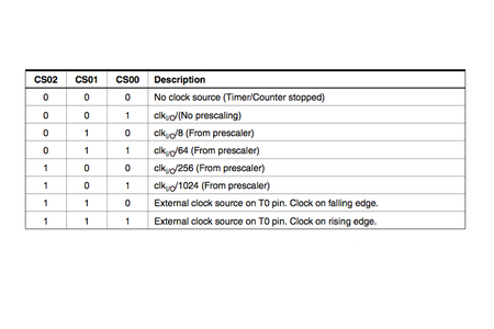
So a 1 prescaler will increment the counter at 16MHz, an 8 prescaler will increment it at 2MHz, a 64 prescaler = 250kHz, and so on. As indicated in the tables above, the prescaler can equal 1, 8, 64, 256, and 1024. (I'll explain the meaning of CS12, CS11, and CS10 in the next step.)
Now you can calculate the interrupt frequency with the following equation:
interrupt frequency (Hz) = (Arduino clock speed 16,000,000Hz) / (prescaler * (compare match register + 1))
the +1 is in there because the compare match register is zero indexed
rearranging the equation above, you can solve for the compare match register value that will give your desired interrupt frequency:
compare match register = [ 16,000,000Hz/ (prescaler * desired interrupt frequency) ] - 1
remember that when you use timers 0 and 2 this number must be less than 256, and less than 65536 for timer1
so if you wanted an interrupt every second (frequency of 1Hz):
compare match register = [16,000,000 / (prescaler * 1) ] -1
with a prescaler of 1024 you get:
compare match register = [16,000,000 / (1024 * 1) ] -1
= 15,624
since 256 < 15,624 < 65,536, you must use timer1 for this interrupt.
Step 2: Structuring Timer Interrupts


Timer setup code is done inside the setup(){} function in an Arduino sketch.
The code involved for setting up timer interrupts is a little daunting to look at, but it's actually not that hard. I pretty much just copy the same main chunk of code and change the prescaler and compare match register to set the correct interrupt frequency.
The main structure of the interrupt setup looks like this:
//https://www.instructables.com/id/Arduino-Timer-Interrupts/

void setup(){

cli();//stop interrupts

//set timer0 interrupt at 2kHz
  TCCR0A = 0;// set entire TCCR0A register to 0
  TCCR0B = 0;// same for TCCR0B
  TCNT0  = 0;//initialize counter value to 0
  // set compare match register for 2khz increments
  OCR0A = 124;// = (16*10^6) / (2000*64) - 1 (must be <256)
  // turn on CTC mode
  TCCR0A |= (1 << WGM01);
  // Set CS01 and CS00 bits for 64 prescaler
  TCCR0B |= (1 << CS01) | (1 << CS00);
  // enable timer compare interrupt
  TIMSK0 |= (1 << OCIE0A);

//set timer1 interrupt at 1Hz
  TCCR1A = 0;// set entire TCCR1A register to 0
  TCCR1B = 0;// same for TCCR1B
  TCNT1  = 0;//initialize counter value to 0
  // set compare match register for 1hz increments
  OCR1A = 15624;// = (16*10^6) / (1*1024) - 1 (must be <65536)
  // turn on CTC mode
  TCCR1B |= (1 << WGM12);
  // Set CS10 and CS12 bits for 1024 prescaler
  TCCR1B |= (1 << CS12) | (1 << CS10);
  // enable timer compare interrupt
  TIMSK1 |= (1 << OCIE1A);

//set timer2 interrupt at 8kHz
  TCCR2A = 0;// set entire TCCR2A register to 0
  TCCR2B = 0;// same for TCCR2B
  TCNT2  = 0;//initialize counter value to 0
  // set compare match register for 8khz increments
  OCR2A = 249;// = (16*10^6) / (8000*8) - 1 (must be <256)
  // turn on CTC mode
  TCCR2A |= (1 << WGM21);
  // Set CS21 bit for 8 prescaler
  TCCR2B |= (1 << CS21);
  // enable timer compare interrupt
  TIMSK2 |= (1 << OCIE2A);


sei();//allow interrupts

}//end setup
Notice how the value of OCR#A (the compare match value) changes for each of these timer setups. As explained in the last step, this was calculated according to the following equation:
compare match register = [ 16,000,000Hz/ (prescaler * desired interrupt frequency) ] - 1
remember that when you use timers 0 and 2 this number must be less than 256, and less than 65536 for timer1
Also notice how the setups between the three timers differ slightly in the line which turns on CTC mode:
TCCR0A |= (1 << WGM01);//for timer0
TCCR1B |= (1 << WGM12);//for timer1
TCCR2A |= (1 << WGM21);//for timer2
This follows directly from the datasheet of the ATMEL 328/168.
Finally, notice how the setup for the prescalers follows the tables in the last step (the table for timer 0 is repeated above),
TCCR2B |= (1 << CS22); // Set CS#2 bit for 64 prescaler for timer 2
TCCR1B |= (1 << CS11); // Set CS#1 bit for 8 prescaler for timer 1
TCCR0B |= (1 << CS02) | (1 << CS00); // Set CS#2 and CS#0 bits for 1024 prescaler for timer 0
Notice in the last step that there are different prescaling options for the different timers. For example, timer2 does not have the option of 1024 prescaler.
The commands you want to execute during these timer interrupts are located in the Arduino sketch encapsulated in the following:
ISR(TIMER0_COMPA_vect){ //change the 0 to 1 for timer1 and 2 for timer2
//interrupt commands here
}
This bit of code should be located outside the setup() and loop() functions. Also, try to keep the interrupt routine as short as possible, especially if you are interrupting at a high frequency. It may even be worth addressing the ports/pins of the ATMEL chip directly instead of using the digitalWrite() and digitalRead() functions. You can find more info about that here.
Example- the following sketch sets up and executes 3 timer interrupts:
//timer interrupts
//by Amanda Ghassaei
//June 2012
//https://www.instructables.com/id/Arduino-Timer-Interrupts/

/*
 * This program is free software; you can redistribute it and/or modify
 * it under the terms of the GNU General Public License as published by
 * the Free Software Foundation; either version 3 of the License, or
 * (at your option) any later version.
 *
*/

//timer setup for timer0, timer1, and timer2.
//For arduino uno or any board with ATMEL 328/168.. diecimila, duemilanove, lilypad, nano, mini...

//this code will enable all three arduino timer interrupts.
//timer0 will interrupt at 2kHz
//timer1 will interrupt at 1Hz
//timer2 will interrupt at 8kHz

//storage variables
boolean toggle0 = 0;
boolean toggle1 = 0;
boolean toggle2 = 0;

void setup(){

  //set pins as outputs
  pinMode(8, OUTPUT);
  pinMode(9, OUTPUT);
  pinMode(13, OUTPUT);

cli();//stop interrupts

//set timer0 interrupt at 2kHz
  TCCR0A = 0;// set entire TCCR2A register to 0
  TCCR0B = 0;// same for TCCR2B
  TCNT0  = 0;//initialize counter value to 0
  // set compare match register for 2khz increments
  OCR0A = 124;// = (16*10^6) / (2000*64) - 1 (must be <256)
  // turn on CTC mode
  TCCR0A |= (1 << WGM01);
  // Set CS01 and CS00 bits for 64 prescaler
  TCCR0B |= (1 << CS01) | (1 << CS00);
  // enable timer compare interrupt
  TIMSK0 |= (1 << OCIE0A);

//set timer1 interrupt at 1Hz
  TCCR1A = 0;// set entire TCCR1A register to 0
  TCCR1B = 0;// same for TCCR1B
  TCNT1  = 0;//initialize counter value to 0
  // set compare match register for 1hz increments
  OCR1A = 15624;// = (16*10^6) / (1*1024) - 1 (must be <65536)
  // turn on CTC mode
  TCCR1B |= (1 << WGM12);
  // Set CS12 and CS10 bits for 1024 prescaler
  TCCR1B |= (1 << CS12) | (1 << CS10);
  // enable timer compare interrupt
  TIMSK1 |= (1 << OCIE1A);

//set timer2 interrupt at 8kHz
  TCCR2A = 0;// set entire TCCR2A register to 0
  TCCR2B = 0;// same for TCCR2B
  TCNT2  = 0;//initialize counter value to 0
  // set compare match register for 8khz increments
  OCR2A = 249;// = (16*10^6) / (8000*8) - 1 (must be <256)
  // turn on CTC mode
  TCCR2A |= (1 << WGM21);
  // Set CS21 bit for 8 prescaler
  TCCR2B |= (1 << CS21);
  // enable timer compare interrupt
  TIMSK2 |= (1 << OCIE2A);


sei();//allow interrupts

}//end setup

ISR(TIMER0_COMPA_vect){//timer0 interrupt 2kHz toggles pin 8
//generates pulse wave of frequency 2kHz/2 = 1kHz (takes two cycles for full wave- toggle high then toggle low)
  if (toggle0){
    digitalWrite(8,HIGH);
    toggle0 = 0;
  }
  else{
    digitalWrite(8,LOW);
    toggle0 = 1;
  }
}

ISR(TIMER1_COMPA_vect){//timer1 interrupt 1Hz toggles pin 13 (LED)
//generates pulse wave of frequency 1Hz/2 = 0.5kHz (takes two cycles for full wave- toggle high then toggle low)
  if (toggle1){
    digitalWrite(13,HIGH);
    toggle1 = 0;
  }
  else{
    digitalWrite(13,LOW);
    toggle1 = 1;
  }
}

ISR(TIMER2_COMPA_vect){//timer1 interrupt 8kHz toggles pin 9
//generates pulse wave of frequency 8kHz/2 = 4kHz (takes two cycles for full wave- toggle high then toggle low)
  if (toggle2){
    digitalWrite(9,HIGH);
    toggle2 = 0;
  }
  else{
    digitalWrite(9,LOW);
    toggle2 = 1;
  }
}


void loop(){
  //do other things here
}
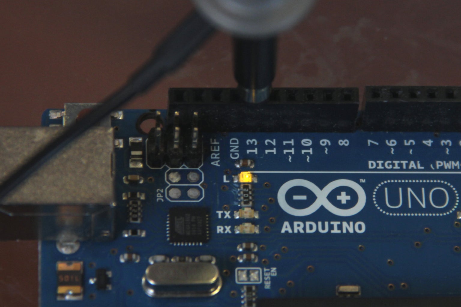
The images above show the outputs from these timer interrupts. Fig 1 shows a square wave oscillating between 0 and 5V at 1kHz (timer0 interrupt), fig 2 shows the LED attached to pin 13 turning on for one second then turning off for one second (timer1 interrupt), fig 3 shows a pulse wave oscillating between 0 and 5V at a frequency of 4khz (timer2 interrupt).
Step 3: Example 1: Bike Speedometer
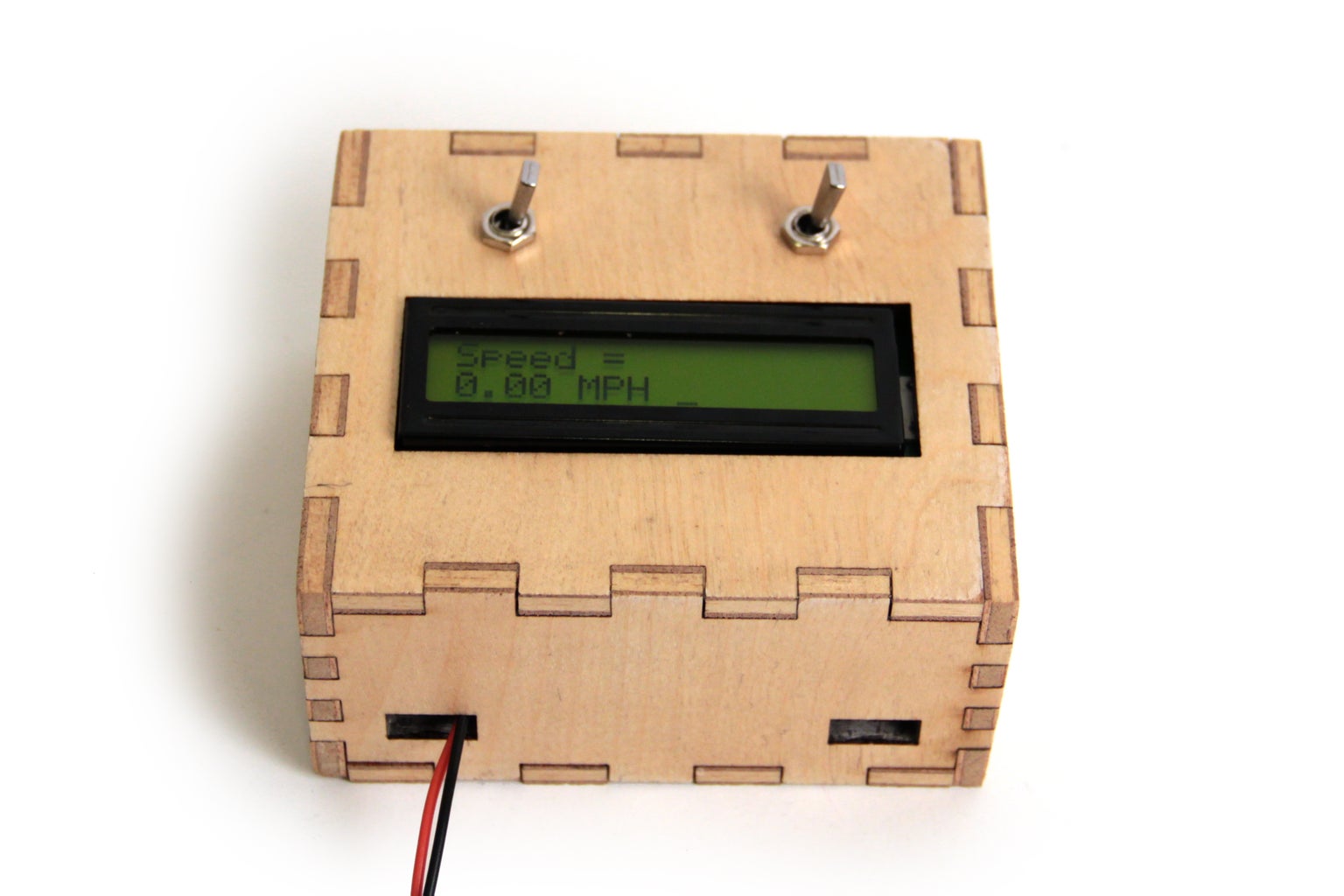

I set timer 1 to interrupt every ms (frequency of 1kHz) to measure the magnetic switch. If the magnet is passing by the switch, the signal from the switch is high and the variable "time" gets set to zero. If the magnet is not near the switch "time" gets incremented by 1. This way "time" is actually just a measurement of the amount of time in milliseconds that has passed since the magnet last passed by the magnetic switch. This info is used later in the code to calculate rpm and mph of the bike.
Here's the bit of code that sets up timer1 for 1kHz interrupts
cli();//stop interrupts
//set timer1 interrupt at 1kHz
TCCR1A = 0;// set entire TCCR1A register to 0
TCCR1B = 0;// same for TCCR1B
TCNT1 = 0;//initialize counter value to 0
// set timer count for 1khz increments
OCR1A = 1999;// = (16*10^6) / (1000*8) - 1
//had to use 16 bit timer1 for this bc 1999>255, but could switch to timers 0 or 2 with larger prescaler
// turn on CTC mode
TCCR1B |= (1 << WGM12);
// Set CS11 bit for 8 prescaler
TCCR1B |= (1 << CS11);
// enable timer compare interrupt
TIMSK1 |= (1 << OCIE1A);
sei();//allow interrupts
Here's the complete code if you want to take a look:
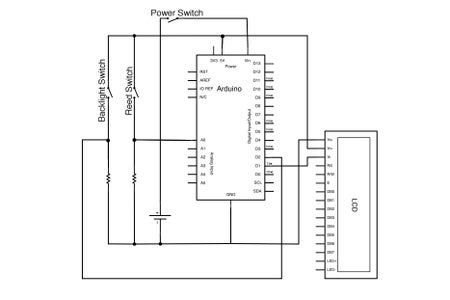
Step 4: Example 2: Serial Communication

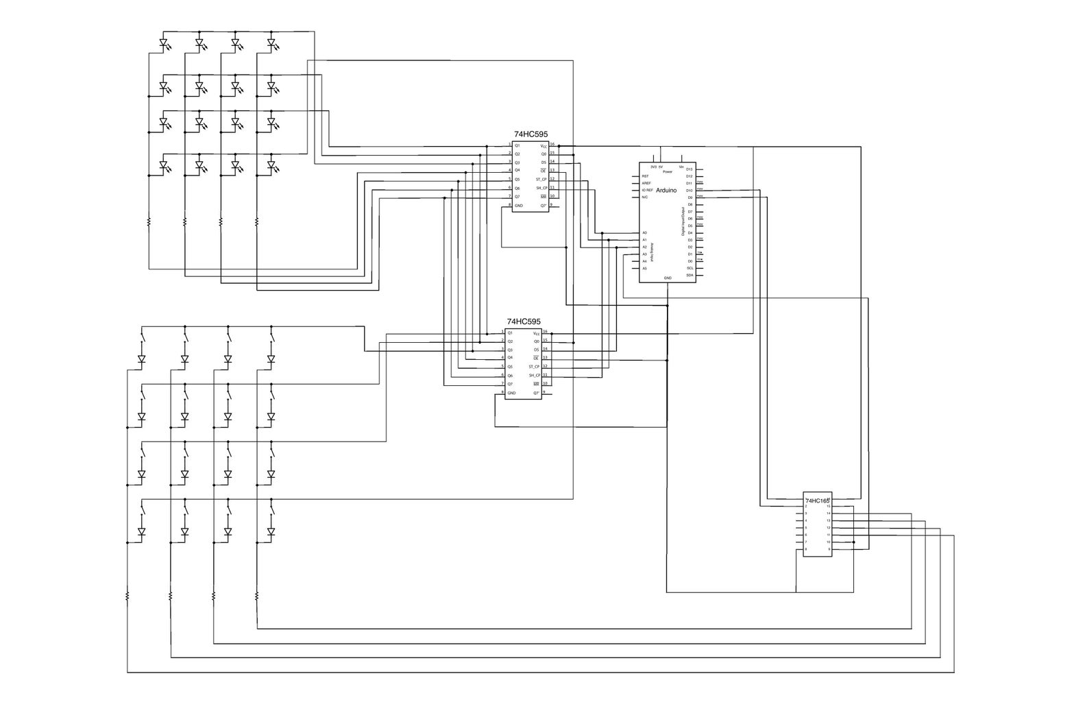
For this project, I used timer2 interrupts to periodically check if there was any incoming serial data, read it, and store it in the matrix "ledData[]". If you take a look at the code you will see that the main loop of the sketch is what is actually responsible for using the info in ledData to light up the correct LEDs and checking on the status of the buttons (a function called "shift()"). The interrupt routine is as short as possible- just checking for incoming bytes and storing them appropriately.
Here is the setup for timer2:
cli();//stop interrupts
//set timer2 interrupt every 128us
TCCR2A = 0;// set entire TCCR2A register to 0
TCCR2B = 0;// same for TCCR2B
TCNT2 = 0;//initialize counter value to 0
// set compare match register for 7.8khz increments
OCR2A = 255;// = (16*10^6) / (7812.5*8) - 1 (must be <256)
// turn on CTC mode
TCCR2A |= (1 << WGM21);
// Set CS21 bit for 8 prescaler
TCCR2B |= (1 << CS21);
// enable timer compare interrupt
TIMSK2 |= (1 << OCIE2A);
sei();//allow interrupts
Here's the complete Arduino sketch:
download the MaxMSP patch below (it will run in Max Runtime as well).
Attachments

Step 5: Example 3: DAC
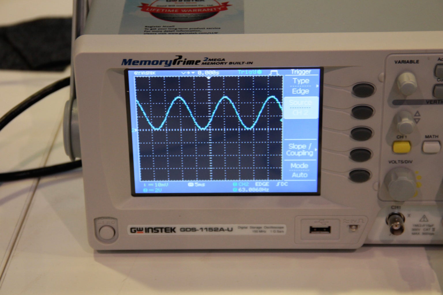


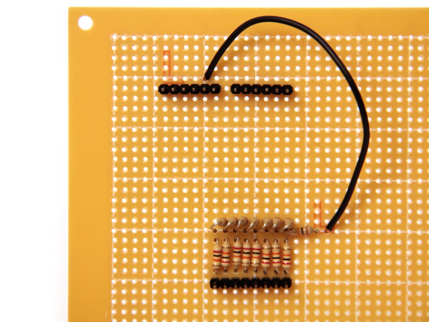

I connected the output from the DAC up to an oscilloscope. If you need help understanding how to use/read the oscilloscope check out this tutorial. I loaded the following code onto the Arduino:
I set up a timer interrupt that increments the variable t at a frequency of 40kHz. Once t reaches 627 it resets back to zero (this happens with a frequency of 40,000/628 = 63Hz). Meanwhile, in the main loop the Arduino sends a value between 0 (00000000 in binary) and 255 (11111111 in binary) to digital pins 0 through 7 (PORTD). It calculates this value with the following equation:
PORTD=byte(127+127*sin(t/100));
So as t increments from 0 to 627 the sine function moves through one complete cycle. The value sent to PORTD is a sine wave with frequency 63Hz and amplitude 127, oscillating around 127. When this is sent through the 8 bit resistor ladder DAC it outputs an oscillating signal around 2.5V with an amplitude of 2.5V and frequency of 63Hz.
The frequency of the sine wave can be doubled by multiplying the (t/100) term by 2, quadrupled by multiplying by 4, and so on...
Also notice that if you increase the frequency of the timer interrupt too much by decreasing the prescaler or OCR2A the sine wave will not output correctly. This is because the sin() function is computationally expensive, and at high interrupt frequencies it does not have enough time to execute. If you are using high frequency interrupts, instead of performing a computation during the interrupt routine, considering storing values in an array and simply calling these values using some kind of index. You can find an example of that in my arduino waveform generator- by storing 20,000 values of sin in an array, I was able to output sine waves with a sampling frequency of 100kHz.
Step 6: Timer and Arduino Functions
One last thing to note- certain timer setups will actually disable some of the Arduino library functions. Timer0 is used by the functions millis() and delay(), if you manually set up timer0, these functions will not work correctly.
Additionally, all three timers underwrite the function analogWrite(). Manually setting up a timer will stop analogWrite() from working.
If there is some portion of your code that you don't want interrupted, considering using cli() and sei() to globally disable and enable interrupts.
You can read more about this on the Arduino website.


