

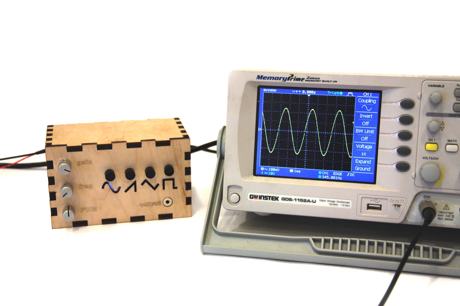
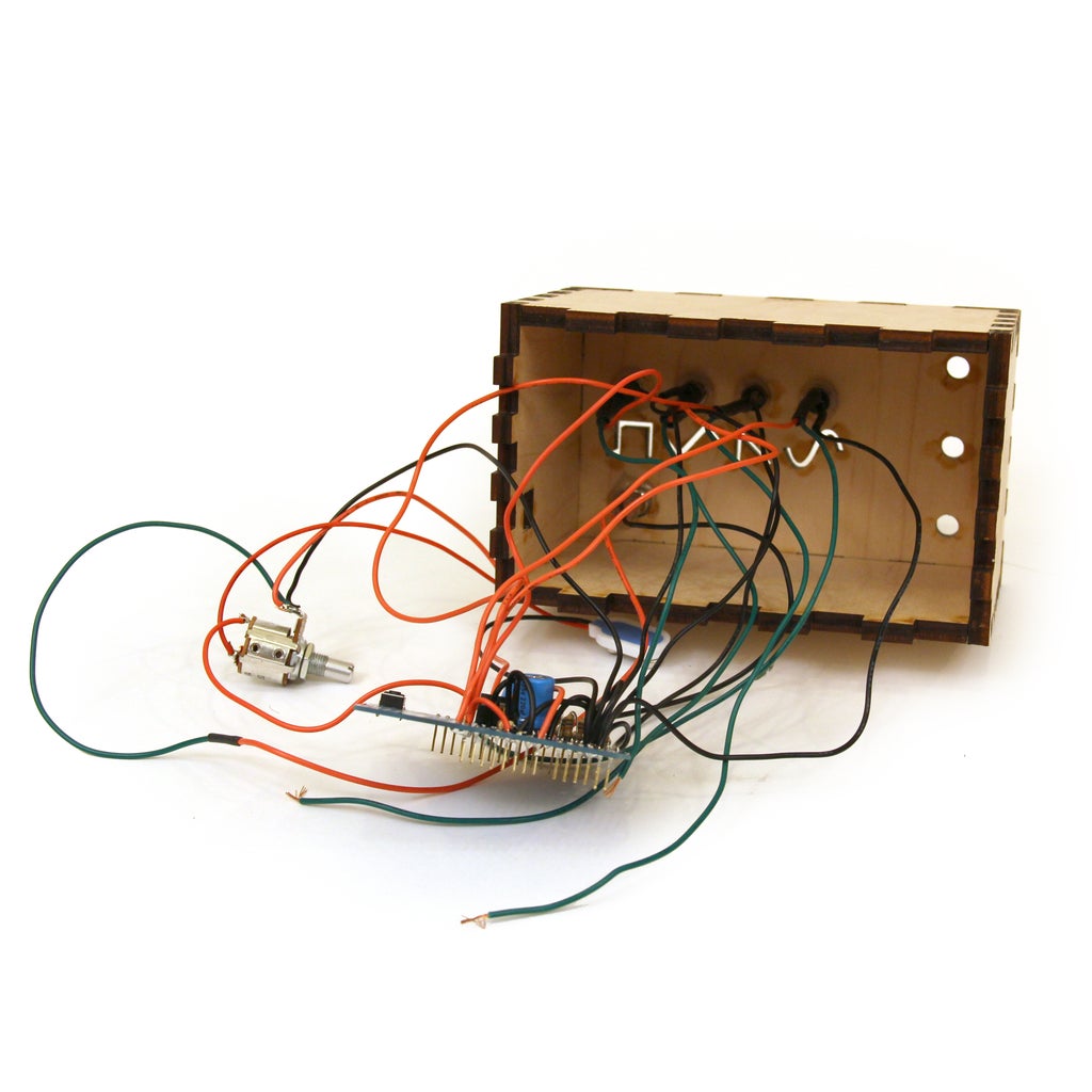
Introduction: Arduino Waveform Generator


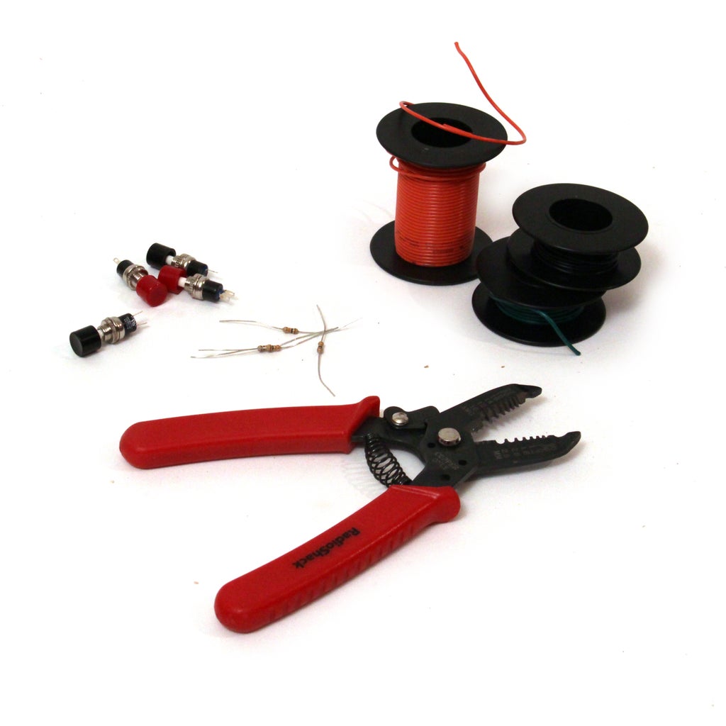
Parts List:
(4x) Mini SPST 1.5-Amp Momentary Pushbutton Switch (2 packages) Radioshack #275-1556
(8x) 10K Ohm 1/4-Watt Carbon Film Resistor (2 packages) Radioshack #271-1335
(9x) 20K Ohm 1/4-Watt Carbon Film Resistor (2 packages)
(1x) 50K-Ohm Linear-Taper Potentiometer Radioshack #271-1716
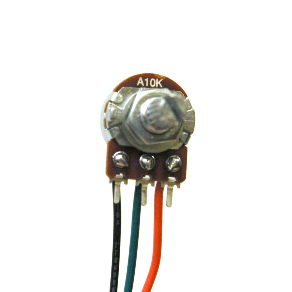
(1x) 10K-Omh Audio-Taper Potentiometer Radioshack #271-1721
(1x) 10K-Ohm Audio Control Potentiometer with SPST Switch Radioshack #271-215
(1x) 1/8" Stereo In-Line Audio Jack Radioshack #274-274
(1x) 10.01µf 50V Ceramic Disc Capacitor Radioshack #55047551
(1x) 4.7K Ohm 1/4-Watt Carbon Film Resistor Radioshack #271-1330
(1x) 8 Pin Socket Radioshack #276-1995
(1x) LM386 Low Voltage Audio Power Amplifier Radioshack #276-1731
(2x) 220µF 35V 20% Radial-lead Electrolytic Capacitor (or anything between 200 and 300 uF) Radioshack #272-1029
(1x) Arduino Uno REV 3 Radioshack #276-128
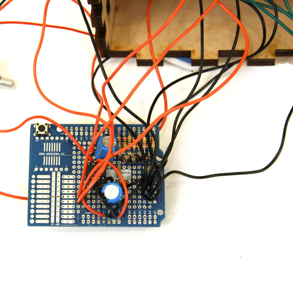
(1x) Arduino Proto Shield Radioshack #276-140
(4x) White Super-bright LED Indicator Radioshack #55050633
(4x) 740 ohm 1/4W 5% Carbon Film Resistor (1 package) Radioshack 271-1317
(1x) 300Ohm resistor
Additional Materials:
Heat Shrink Radioshack #278-1611
22 Gauge Wire Radioshack #278-1224
Solder Radioshack #64-013
Drill
Hot Glue
Glue
Black diffusor material (tissue paper, plastic, etc)
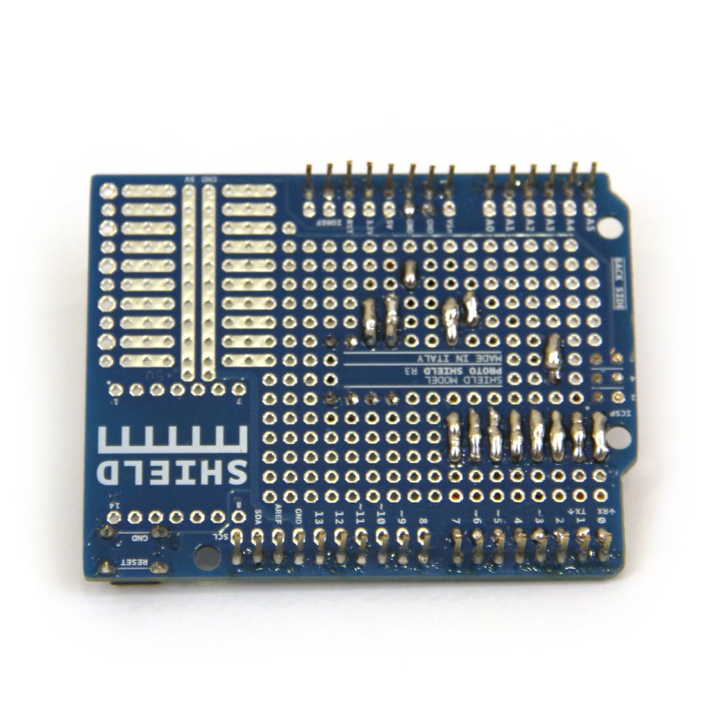
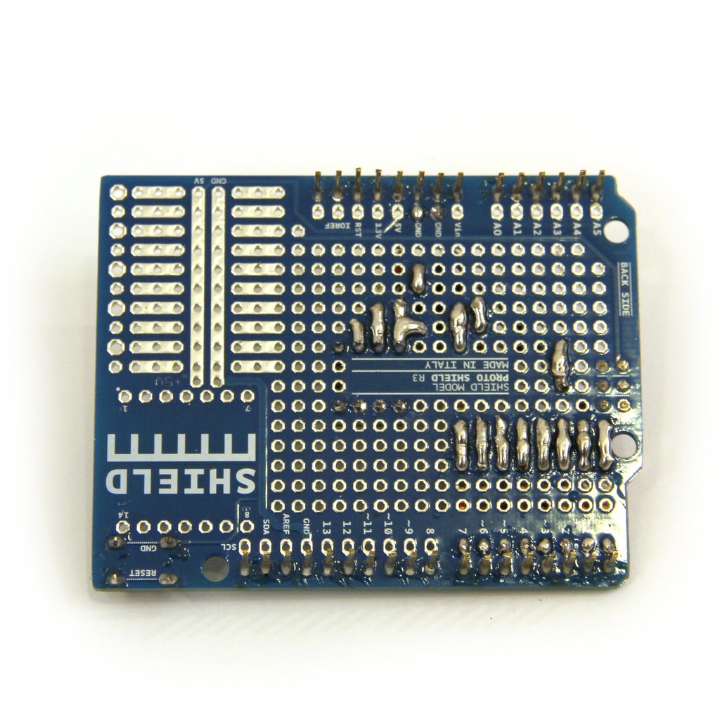
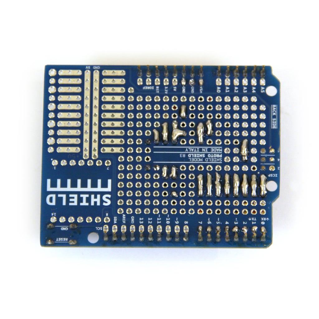
Step 1: Prepare Arduino Proto Shield
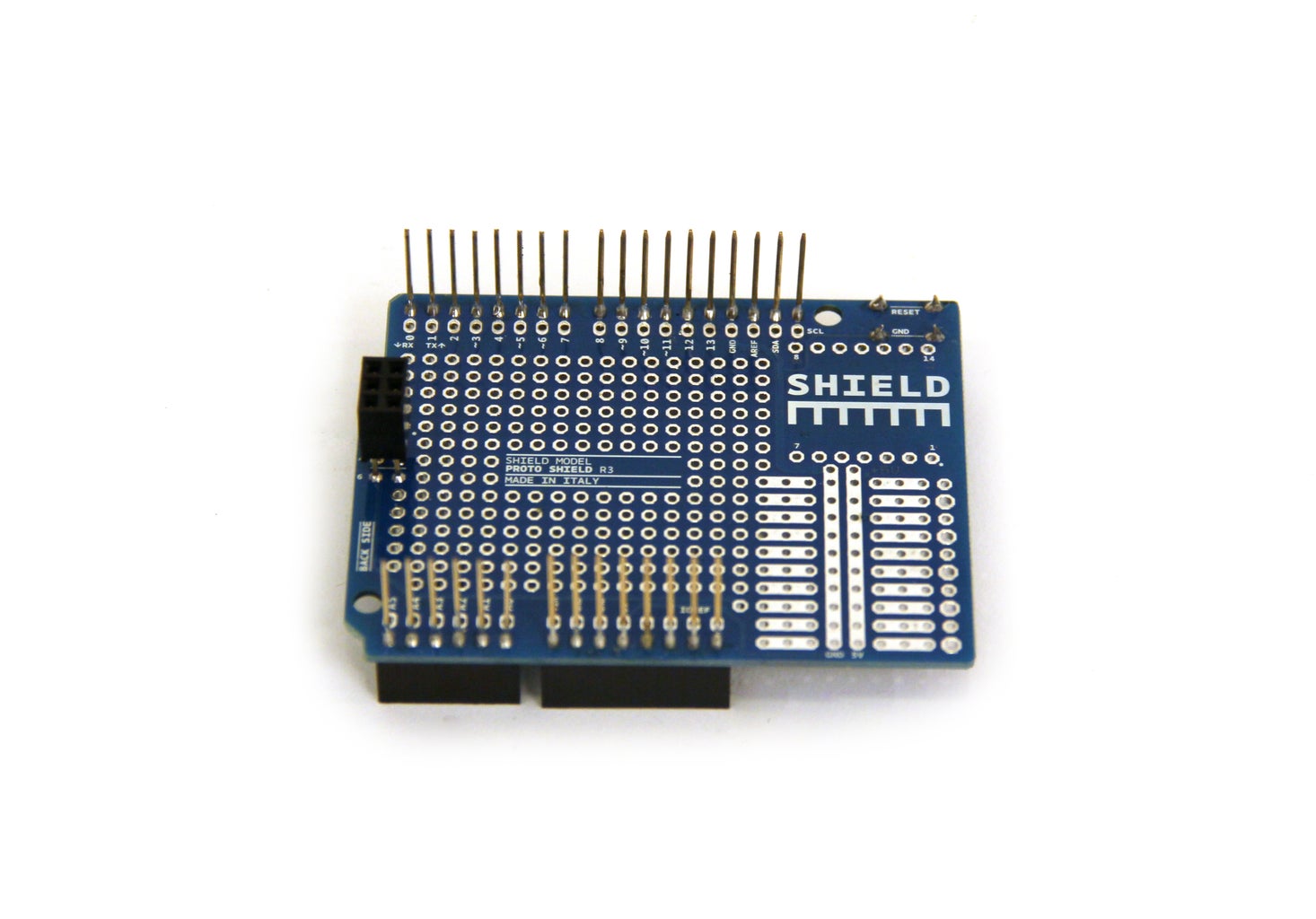
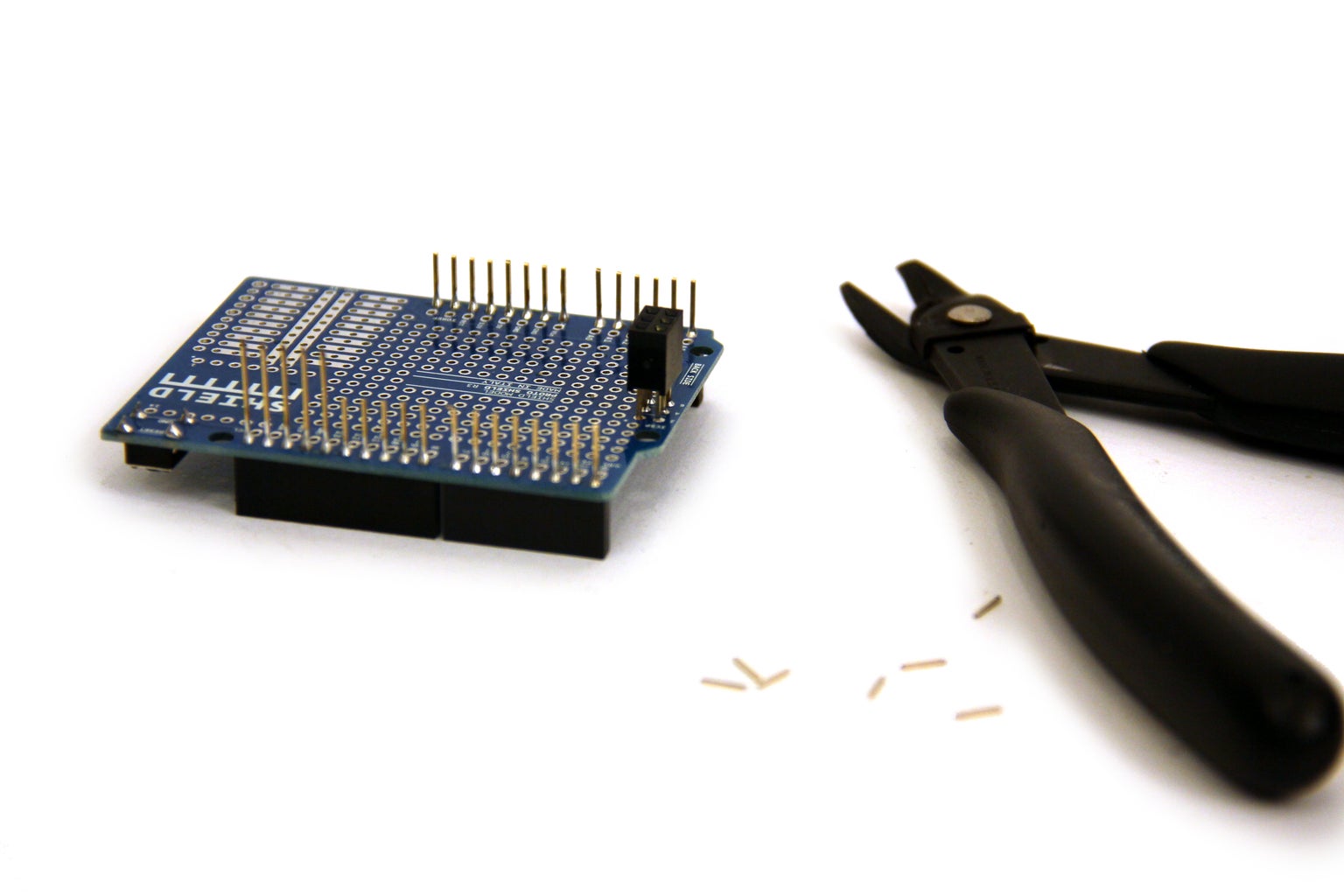
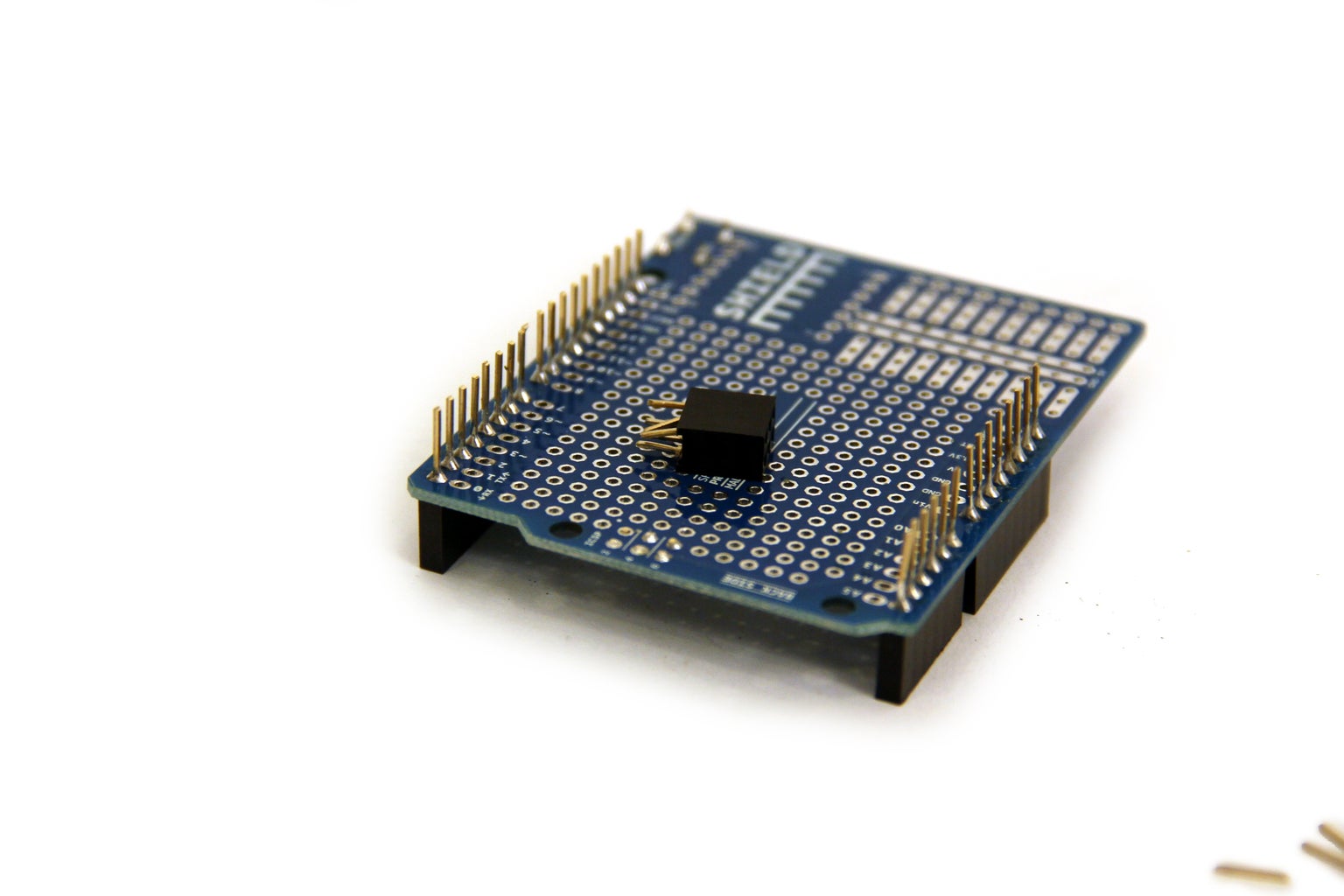


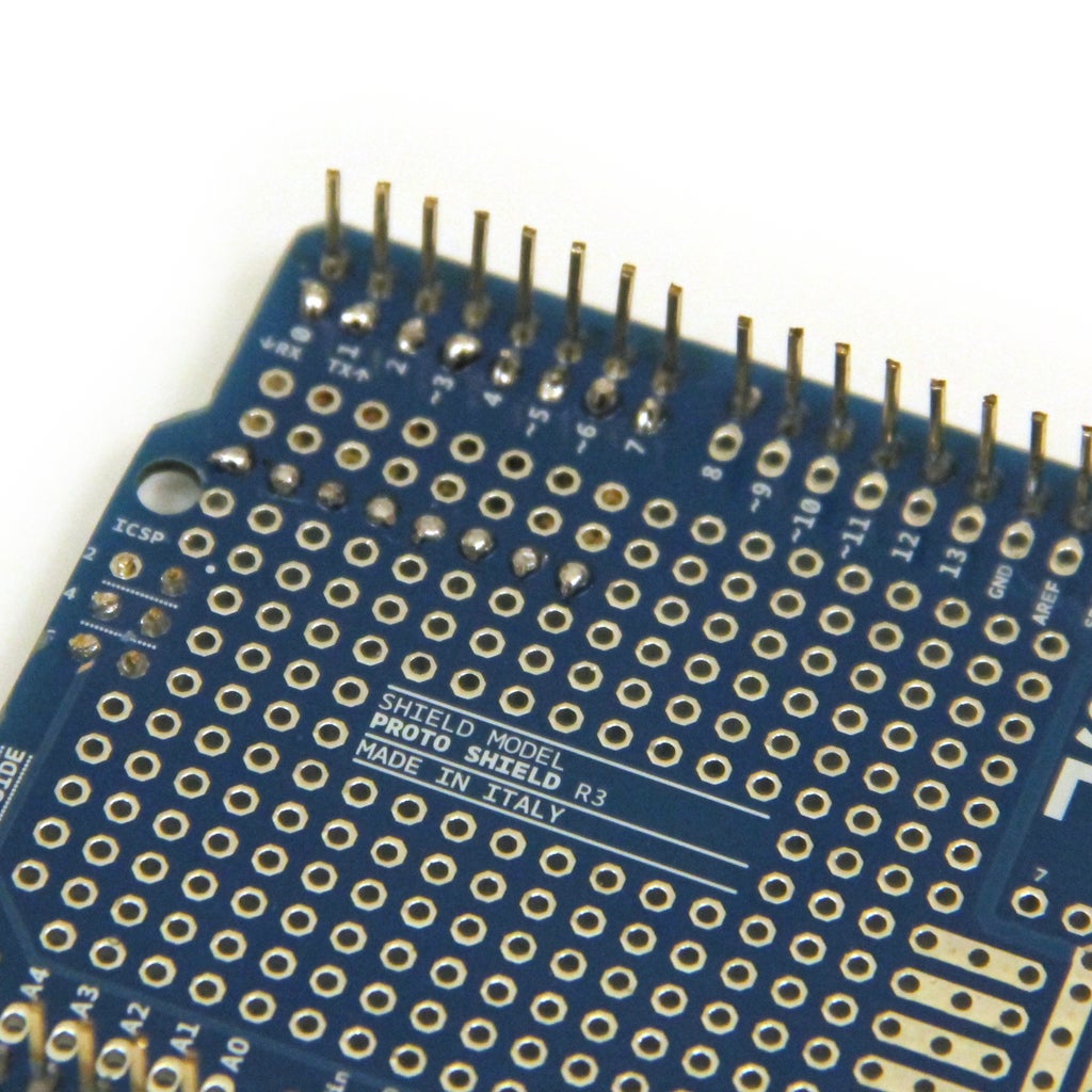
The Arduino Proto Shields are a convenient way to attach circuits to an Arduino, but I like to trim them down a little bit first so they do not take up so much room in the project enclosure. Start by trimming the pins down with a pair of wire cutters. Next, cut off the six pin socket. Finally, cut the sockets from the top of the board.
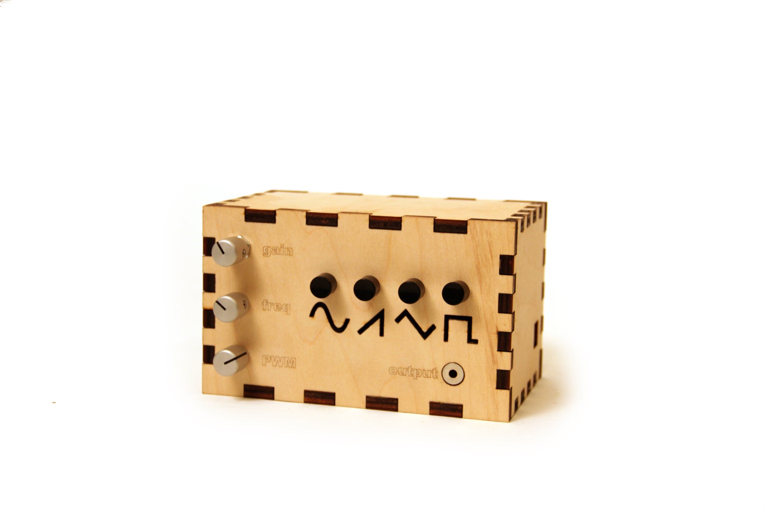
Step 2: Enclosure


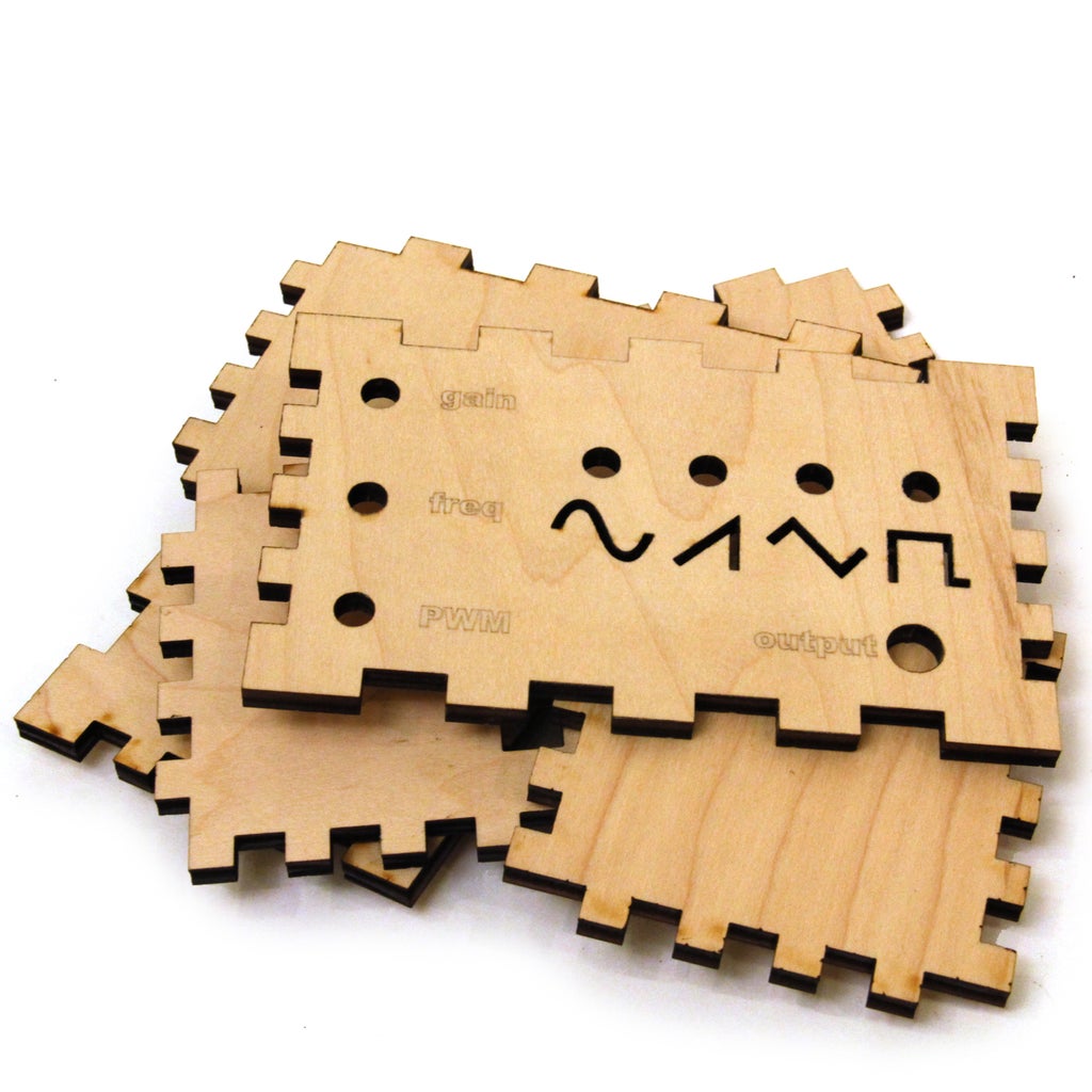
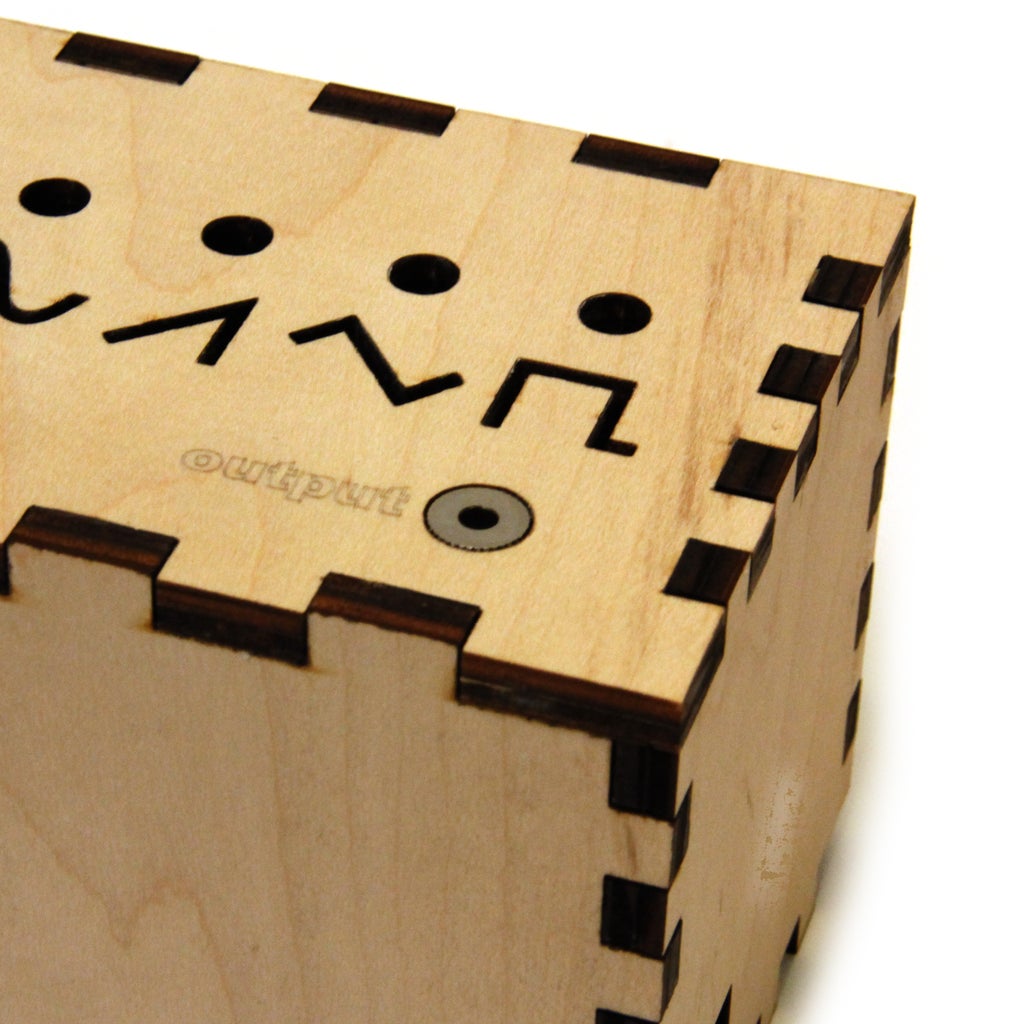
I decided to laser cut a custom enclosure for my project. I designed the enclosure using AutoCAD, Autodesk 123D Make, and Corel Draw, and I've included corel draw and adobe illustrator 2D files as well as the STL, and DWG files from this process below. If you do not have access to a laser cutter, you can use my 2D files a guide and drill the necessary holes in a project enclosure of some kind. Figure 4 shows the holes that should be drilled on the front panel:
(3x) 7mm holes for gain, freq, and PWM pots
(3x) 7mm holes for four push buttons- sin, saw, tri, and pulse
(1x) 10mm hole for audio out
I cut out shapes of all four waveforms in the front of the enclosure so that I could backlight them with indicator LEDs, you may choose to just drill four 5mm holes for these LEDs in the front panel of the enclosure, place one LED under each momentary switch.
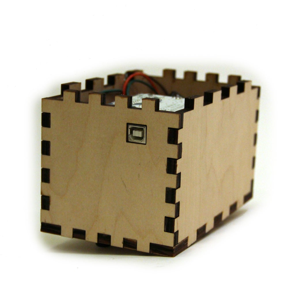
Also include a rectangular (11mm tall, 12mm wide) cutout somewhere on the side of the enclosure for the arduino's usb port.
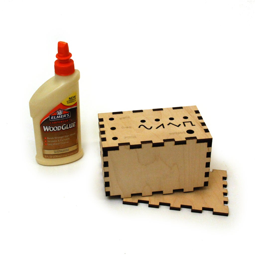
I made my project enclosure out of wood, so I had to glue all the pieces (except the bottom) together with wood glue. I will attach the bottom panel on later in this instructable.

Step 3: Solder Button Leads
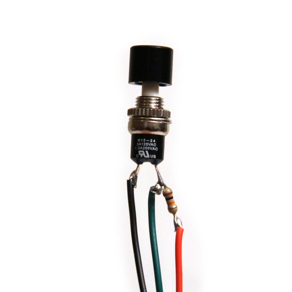

Solder a 10kOhm resistor to one lead of each of the four push buttons. As shown in the second image, solder a green wire to the junction between the button and the resistor and a red wire to the other end of the resistor. Solder a black wire the the second lead of the push button. It's a good idea to cover these connections with a bit of heat shrink to prevent short circuits (fig 2).
Step 4: Install Audio Jack


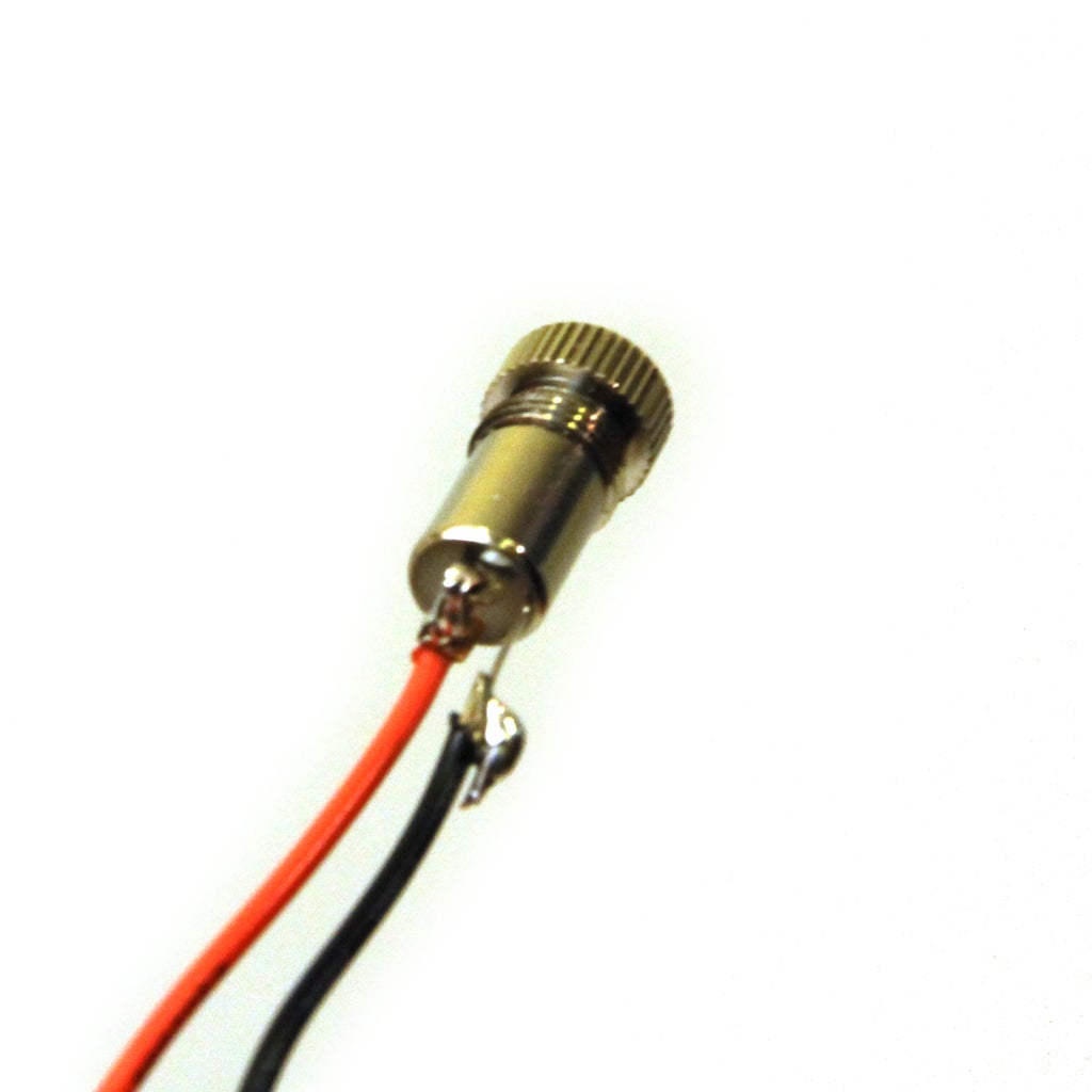
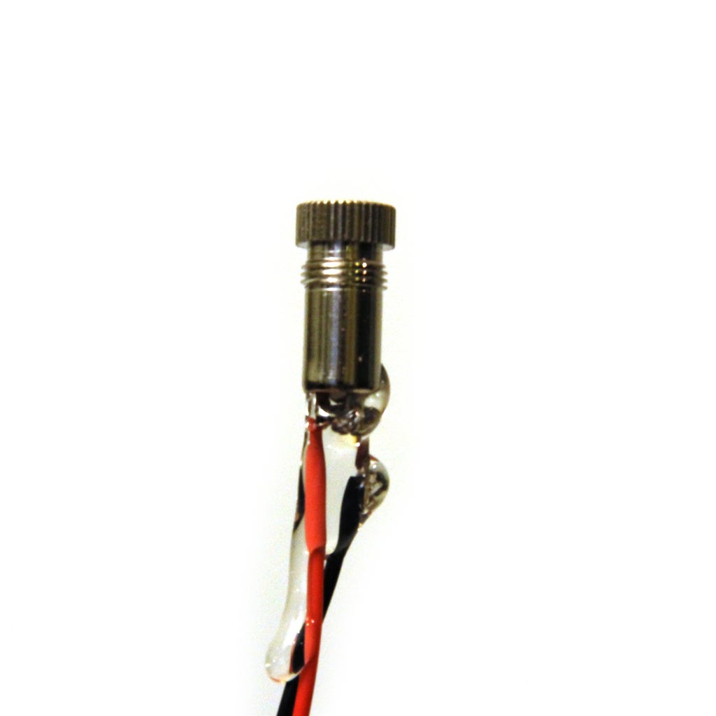
Unscrew the plastic casing from the audio jack. Solder a red wire to the two stereo out pins and solder a black wire to the ground pin (fig 3). I used hot glue to prevent short circuiting the jack and to give the soldering joints some extra support. Finally, mount the audio jack in the enclosure with super glue.
Step 5: Install Buttons

Snap the top of the button off and fit them into the wooden enclosure. Secure with hot glue. Once dried, snap the black button tops back on.
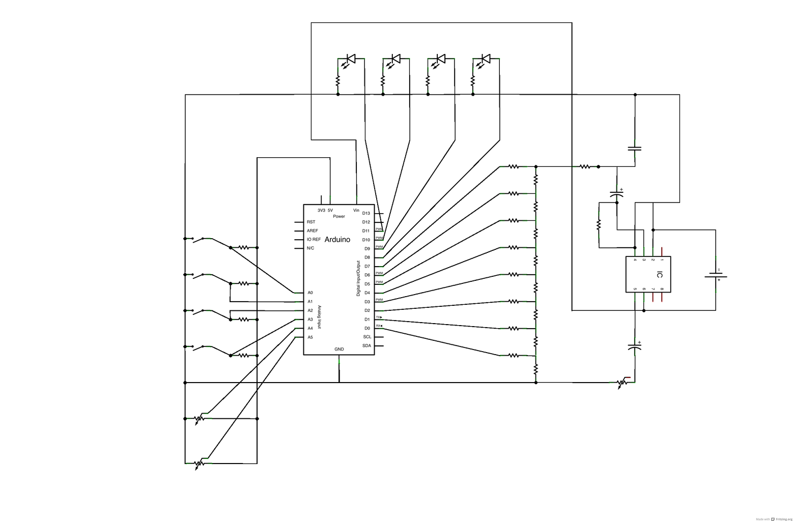
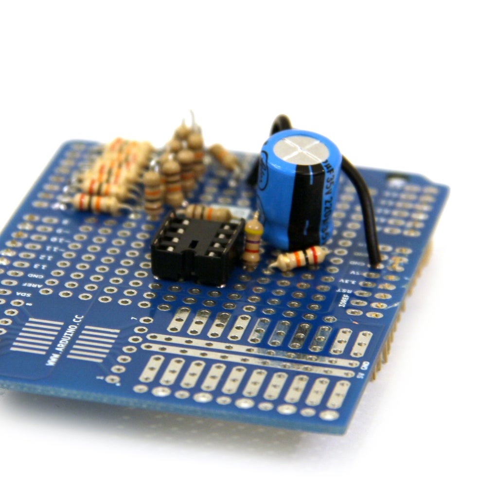
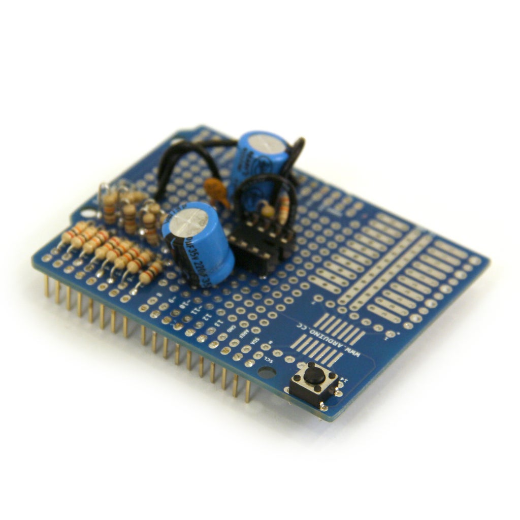
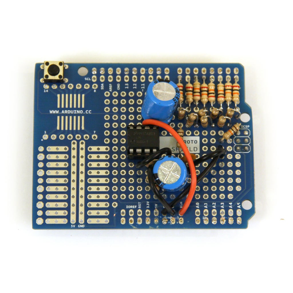
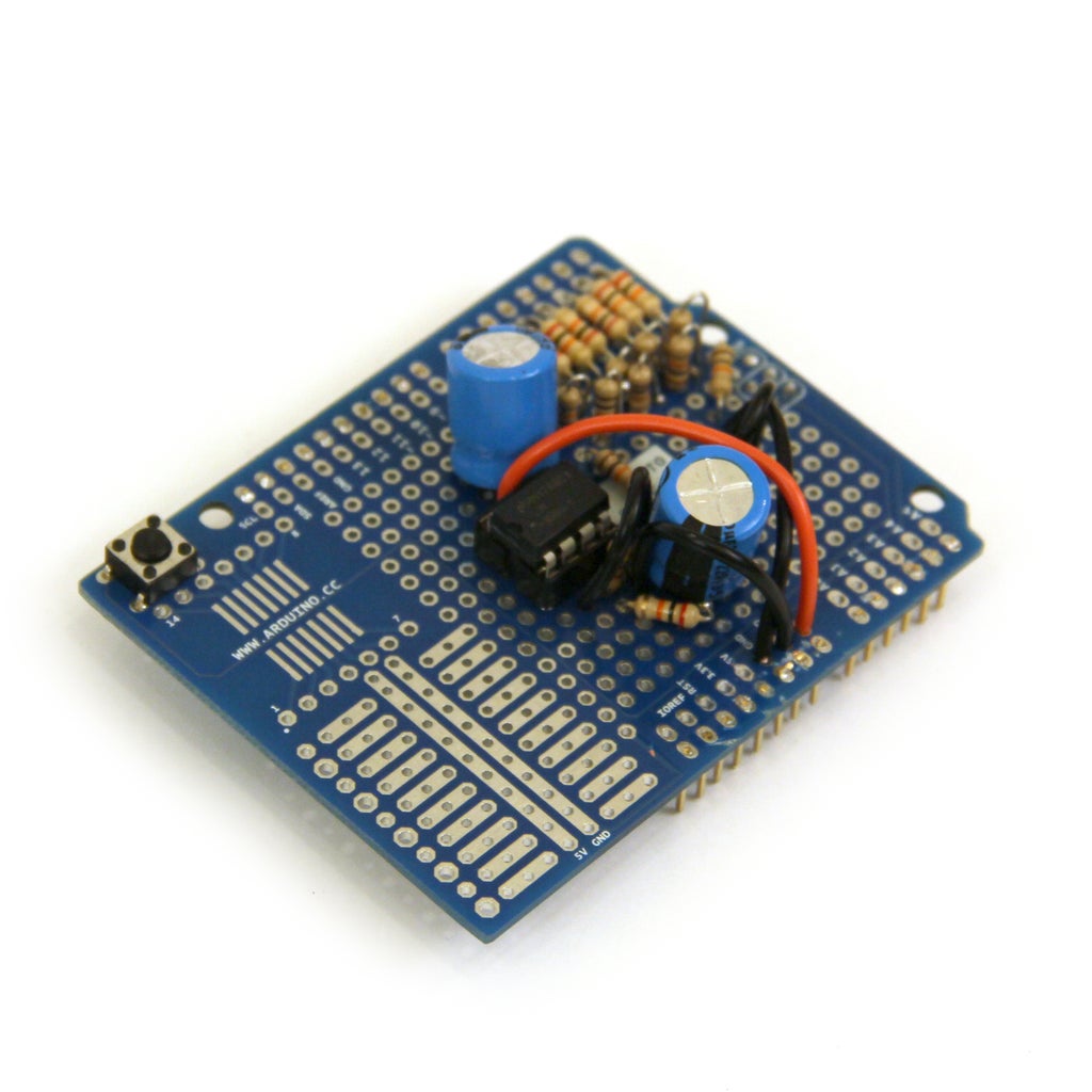
Step 6: R2R DAC on Arduino Shield: Part 1

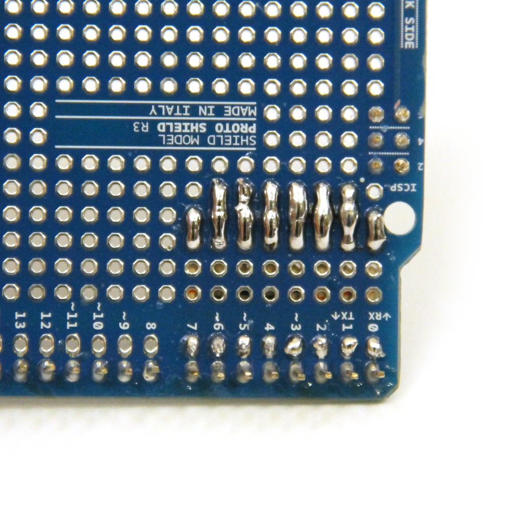
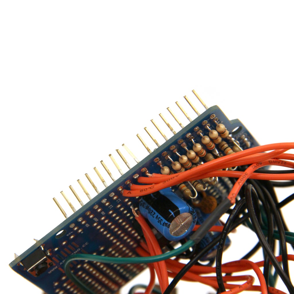
Solder eight 20kOhm resistors to the arduino protoshield. One end of each resistor should connect to digital pins 0-7.
Step 7: R2R DAC on Arduino Shield: Part 1
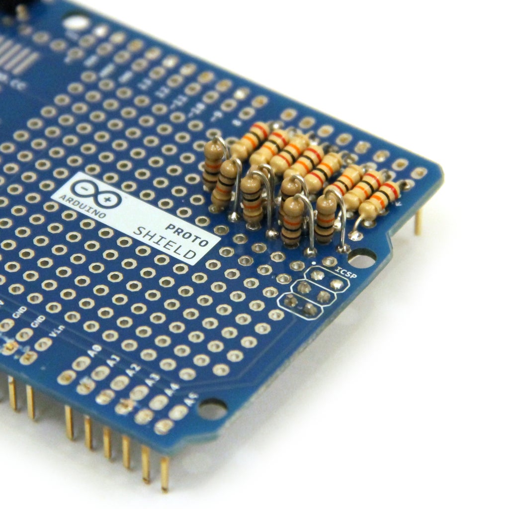
Solder 7 10kOhm resistors to the protoboard so that they bridge the leads of the 8 20kPhm resistors you have just soldered.
Step 8: R2R DAC on Arduino Shield: Part 3
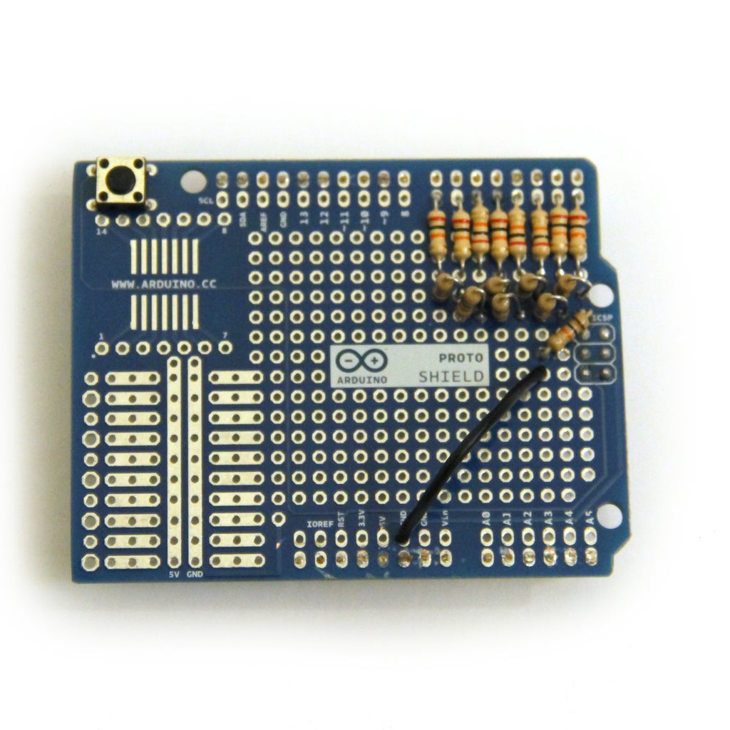

Solder a 20kOhm resistor to the protoshield so that one end is connected to the 10kOhm resistor attached to digital pin 0 and the other end is connected to a jumper wire to ground.
Step 9: IC Socket
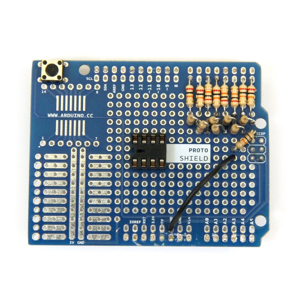

It's a good idea to use sockets for your ICs, this way you won't risk burning the IC with your soldering iron and you can easily replace the IC if it breaks. Solder an 8 pin socket to the protoboard as shown in the image.
Step 10: Low Pass Filter


Use a resistor and capacitor in series to create a low pass filter. Low pass filters let low frequencies pass through and silence (attenuate) high frequencies. Connecting a low pass filter to the output from the dac will smooth out the steps in the wave.
Here's how I calculated the value of the components in my low pass filter:
corner frequency = 1/(2*pi*R*C)
According to Nyquist's Theorum, signals cannot contain frequencies higher than half their sampling rate. If I used a sampling rate of 100kHz, then the highest frequency I can produce is 50kHz.
if I use a 300Ohm resistor and I want a corner frequency of 50kHz:
50000 = 1/(6.28*300*C)
C = 1.06*10^-8 F
round this to:
C = 0.01uF
Connect one end of the the 300Ohm resistor to the 10kOhm resistor connected to digital pin 7. Connect the capacitor to the other end of the 300Ohm resistor. The other side of the cap should connect to ground.
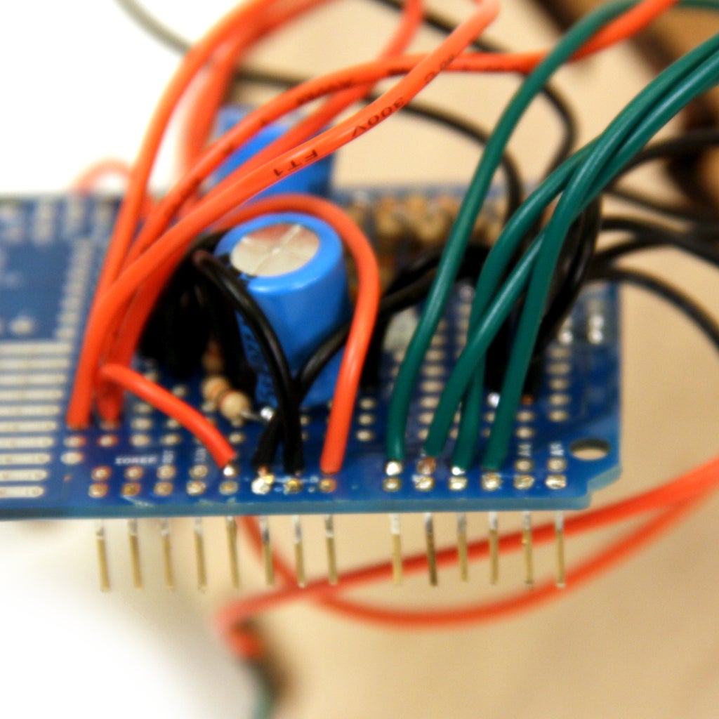
Step 11: Amplifier: Part 1
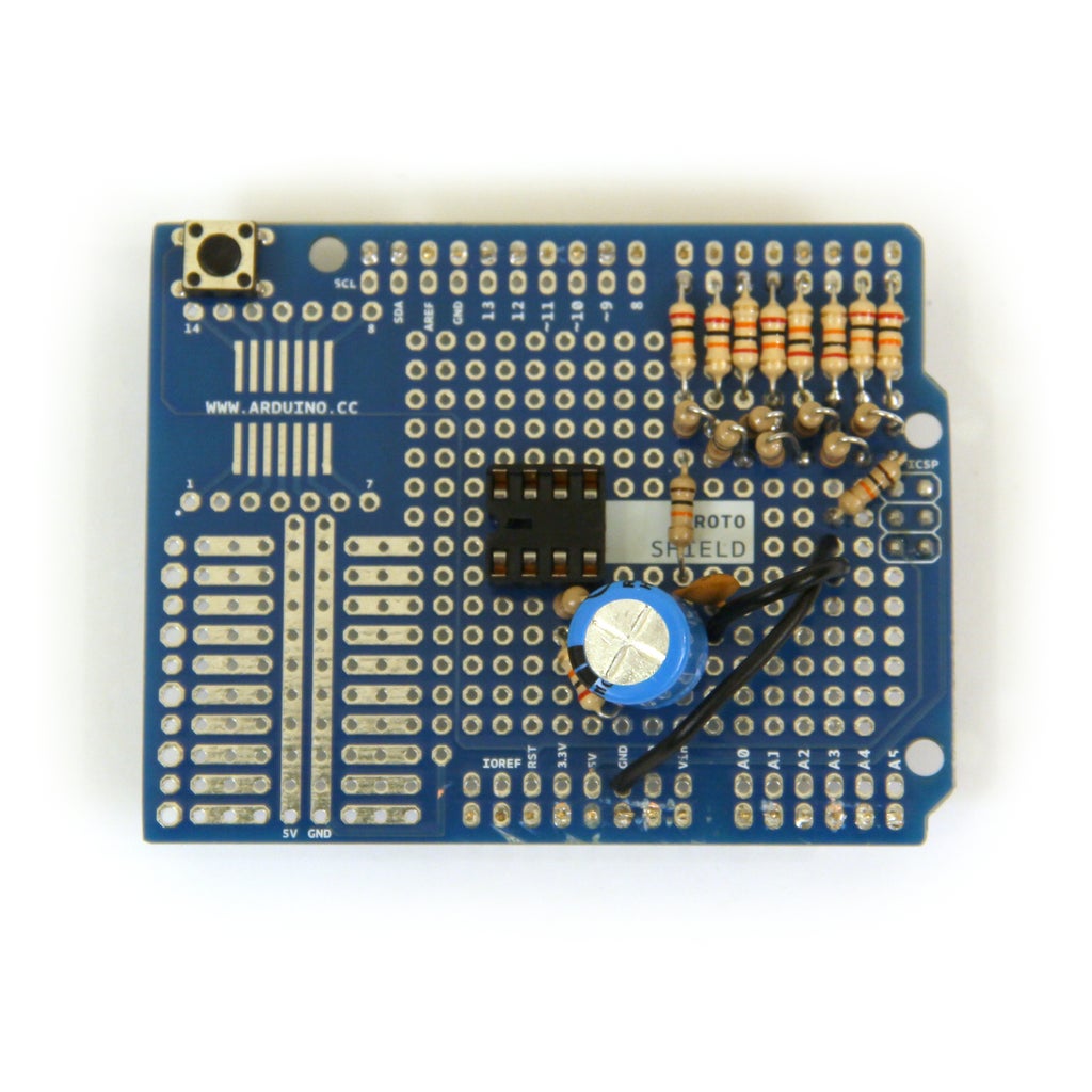

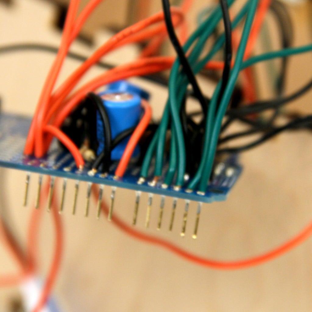
Connect the positive lead of the 220uF capacitor to the junction between the resistor and capacitor of the low pass filter. The other end of the 220uF capacitor connects to a 20kOhm resistor that is connected to pin 3 of the IC socket. A 4.7kOhm resistor bridges pins 3 and 4 of the IC socket.
Step 12: Amplifier: Part 2
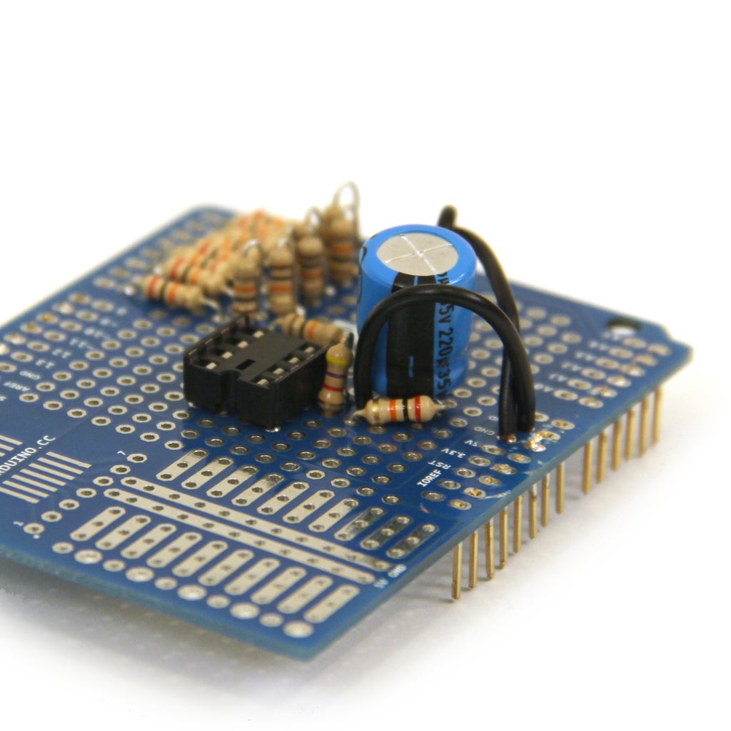
Connect ground to pin 4 of the IC socket.
Step 13: Amplifier: Part 3

Connect the positive lead of a second 200uF capacitor to pin 5 of the IC socket. The other end of the cap will be connected to the gain pot in a later step.
Step 14: Amplifier: Part 4
Connect pin 6 of the IC socket to Vin, pin 2 to ground, and snap the IC into the socket.
Step 15: Wire Gain Pot

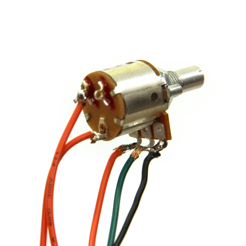
Volume or gain of the audio signal will be controlled with the 10k audio taper pot with switch. Connect the audio out from the amplifier and ground to either side of the potentiometer as indicated in the picture. The middle is audio out, it will be hooked up directly to the audio jack.
Also connect a wire to the bottom and left leads on the back of the pot (figure 2). This is the switch that will be used to connect to power in the next step.
Step 16: Connect to Battery
Connect the black wire from the battery clip to ground on the Arduino Shield. Connect one lead from the gain pot switch to the red wire from the battery clip and connect the other gain pot lead to Vin on the Arduino Shield.
Leave the battery disconnected for now.
Step 17: Connect Output to Headphone Jack
Connect the output from the amplifier (the negative lead of the cap connected to the IC at pin 5) to the red wire we attached to the gain potentiometer in an earlier step. Connect the green wire from the amplitude pot to the red wire connected to the audio jack. Connect the black wire from the audio jack and the black wire from the pot to ground on the Arduino Shield.
Step 18: Wire Buttons
Connect all read leads from the button to 5V and all the black wires to ground on the arduino shield (fig 1). Connect the green wires to analog in 0-3 in the following order:
analog 0 = pulse
analog 1 = triangle
analog 2 = saw
analog 3 = sine
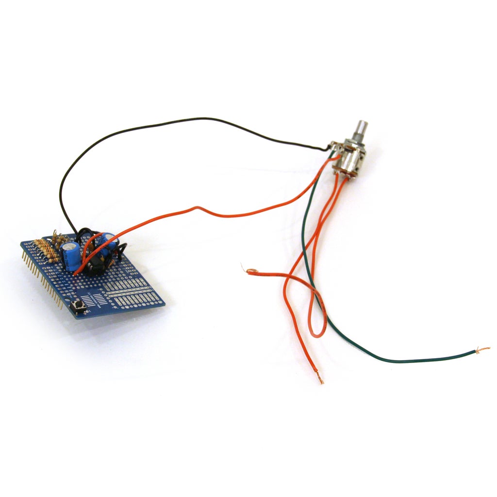
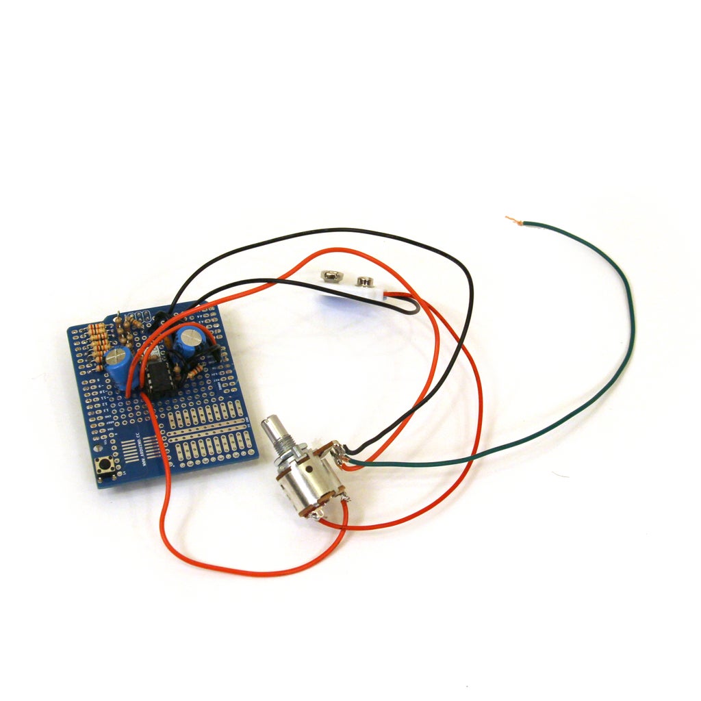
Step 19: Wire Frequency and PWM Pots
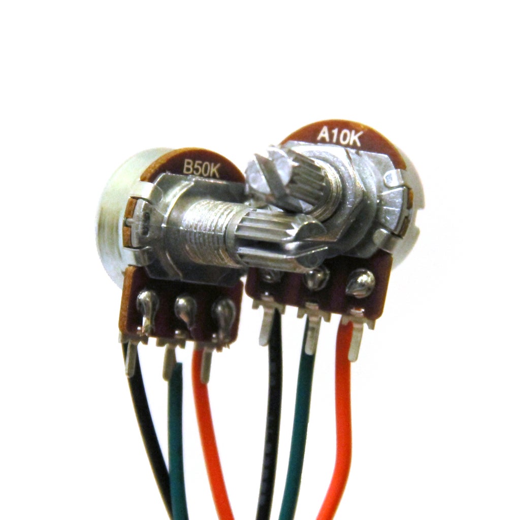
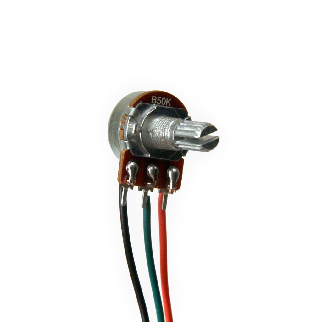
Connect a red, black, and green wire to the 10kOhm and 50kOhm potentiometers as shown in the images. Connect the red lead to 5V and the black leads to ground on the arduino shield. Connect the center green wires to analog pins 4 (PWM) and 5 (frequency).
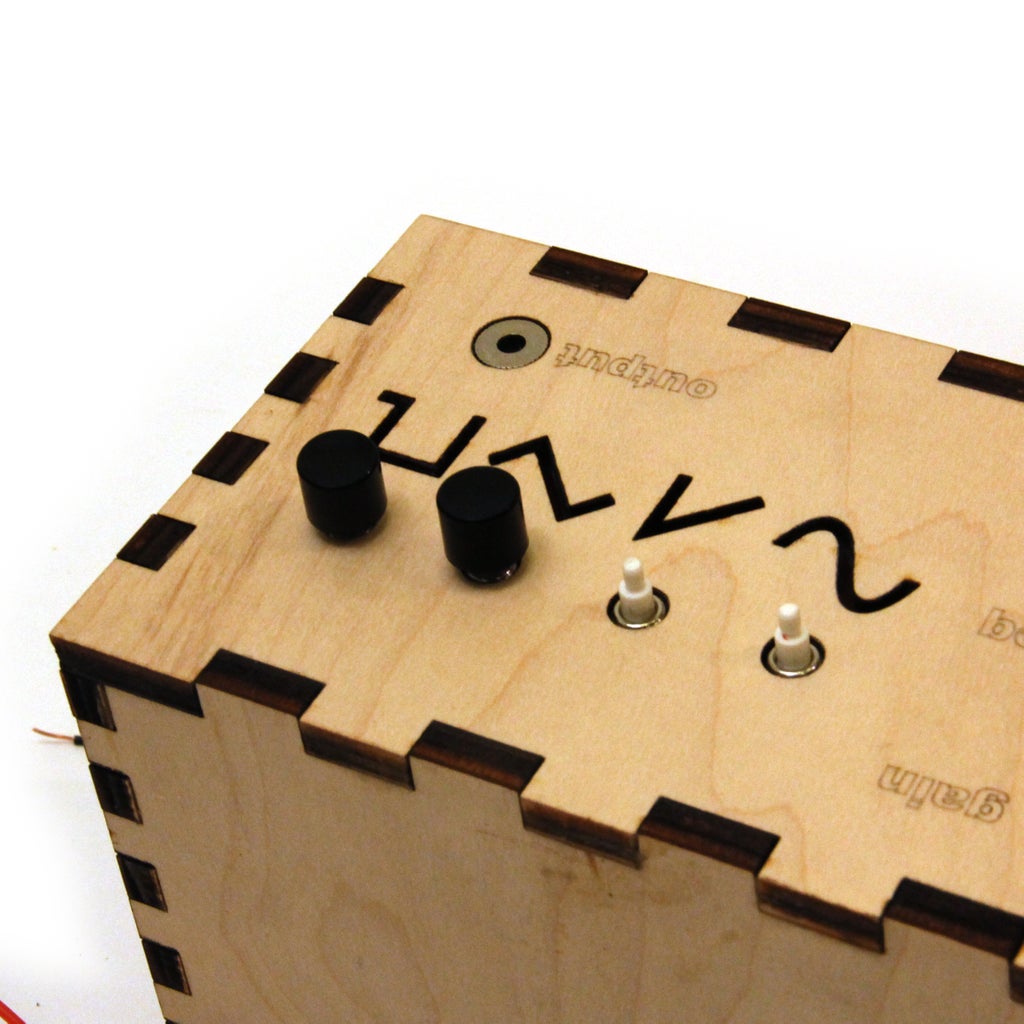
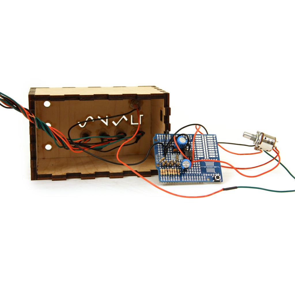
Step 20: Install Pots


Remove the side tab on all of the pots before installing in the enclosure, this will allow them to sit flush against the wood. Remove washer and nut from each of the pots, place pot through hole in enclosure, and secure with nut. Install all three pots in the enclosure.
Step 21: Wire LEDs: Part 1


Attach a 470Ohm resistor to the cathode of each of the four LEDs. Solder a black wire to the other end of the resisotr and a red wire to the anode of the LED. Cover these connections with shrink wrap to prevent short circuiting.
Step 22: Wire LEDs: Part 2
Solder the black leads from all four LEDs to ground on the arduino shield. Solder the red leads to digital pins 8-11.
Step 23: Black Diffuser

Glue a light diffusing material behind the wave cutouts in the front panel. I used a piece of a black plastic garbage bag.
Step 24: Glue LEDs

Glue the LEDs in the enclosure so that they are each pointed towards one of the cutout symbols on the front panel. Here is a table for reference:
digital 8 = pulse
digital 9 = triangle
digital 10 = saw
digital 11 = sine
Step 25: Firmware

Upload the code at the bottom of this step onto the Arduino. The code uses a timer interrupt at a frequency of 100kHz to send new data out to the DAC. The rest of the code monitors the state of the buttons and knobs and adjusts variables accordingly. Since the interrupts occur at such a high frequency, I had to keep the interrupt routine, the piece of code encapsulated in the ISR(TIMER1_COMPA_vect){} as short as possible. Time intensive operations like mathematical operations with floats and using the sin() function take too much time to complete. I used several work around to get by this:
For triangle and saw I created the variables sawByte, triByte, sawInc, and triInc. Every time the frequency changed I calculated the amount that the triangle and saw function would have to increment at a sampling rate of 100kHz:
triInc = 511/period;
if (triInc==0){
triInc = 1;
}
sawInc = 255/period;
if (sawInc==0){
sawInc = 1;
}
then all the needed to be done in the interrupt routine was some simple math:
case 1://triangle
if((period-t) > t);
if (t == 0){
triByte = 0;
}
else{
triByte += triInc;
}
}
else{
triByte -= triInc;
}
if (triByte>255){
triByte = 255;
}
else if (triByte<0){
triByte = 0;
}
wave = triByte;
break;
case 2://saw
if (t=0){
sawByte=0;
}
else{
sawByte+=sawInc;
}
wave = sawByte;
break;
For the sine function, I wrote a simple python script which outputs 20000 values of 127+127sin(x) for one complete cycle:
import math
for x in range(0, 20000):
print str(int(127+127*math.sin(2*math.pi*x*0.00005)),)+str(","),
I stored this array in the Arduino's memory called sine20000[] and recalled the values I needed to send to the DAC. This is much faster than calculating the values individually.
Attachments
Step 26: Last Few Connections
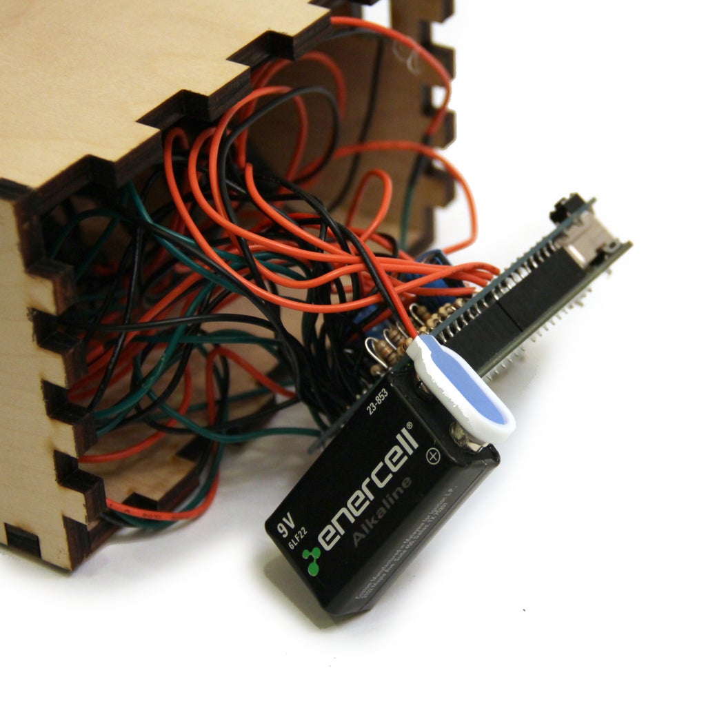

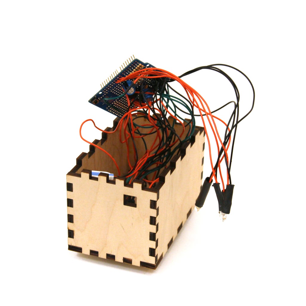
Plug the Arduino into your shield. Connect a 9V battery to the battery clip. Secure these items inside the enclosure. Make sure that the Arduino's usb port is accessible from the outside of the enclosure. Upon startup you should see the sine wave LED light up.
Step 27: Screw Back Panel

Drill four holes in the back panel and secure with screws.
Step 28: Add Knobs
Screw knobs on the three potentiometers.
Step 29: Test
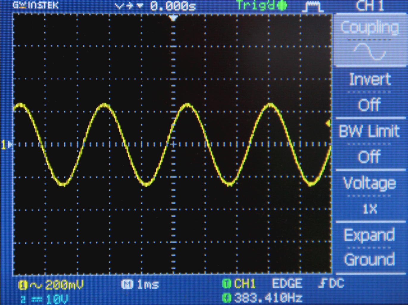

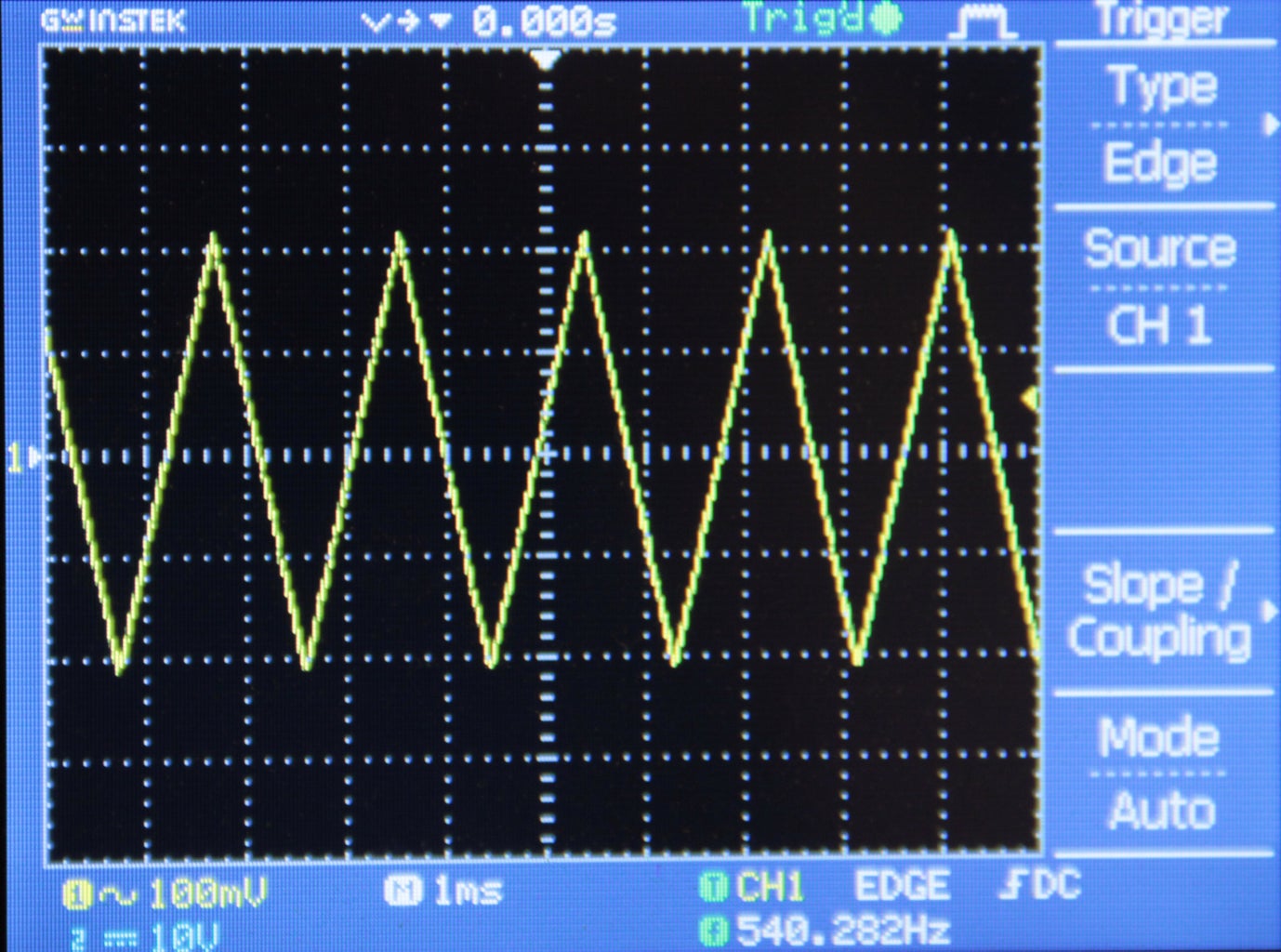
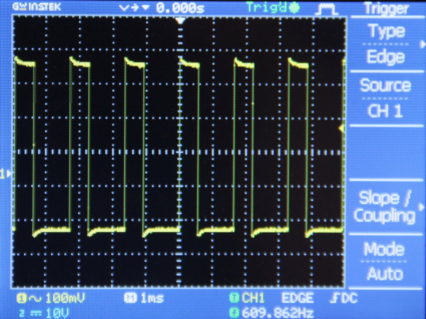
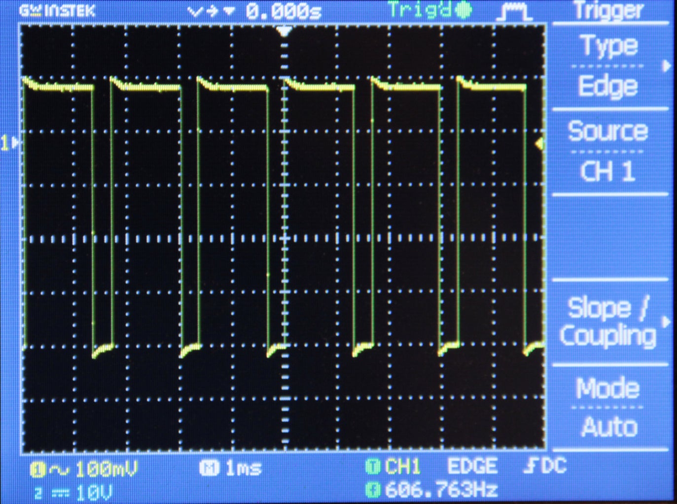
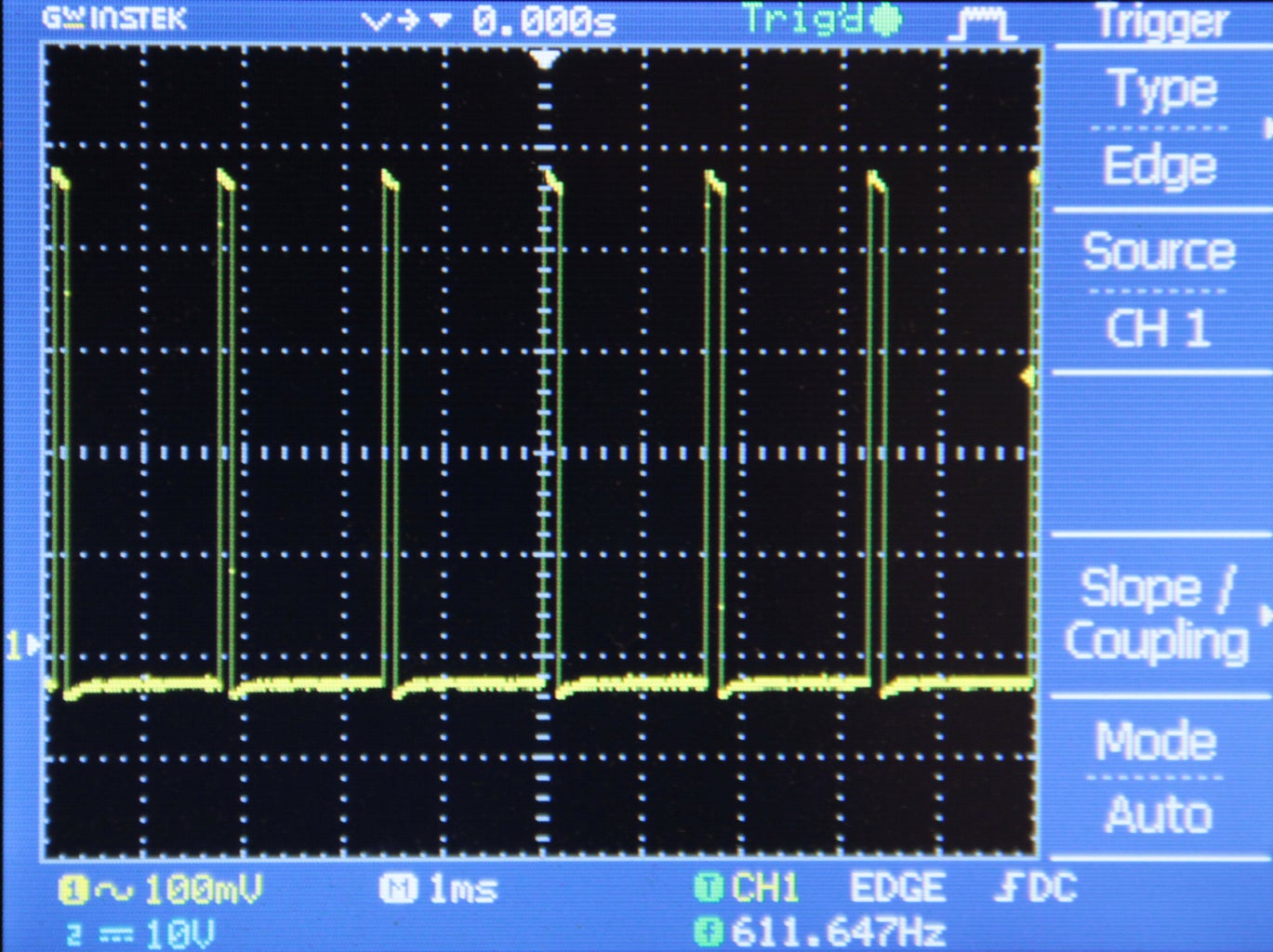
Turn up the gain knob to turn on the function generator. Plug an eighth inch jack into the output and hook up the function generator to an oscilloscope. Test out each of the waveforms and adjust the frequency and gain to make sure they are working properly. Switch the output to pulse and check if the pulse width modulation knob works (figs 4-6).
You will notice that the pulse wave is the only wave which truly ranges from 1Hz to 50kHz. Since the sampling rate is 100kHz, the sine, triangle, and saw waves start to become somewhat unrecognizable at about 25kHz (they are only comprised of 4 samples per cycle- 100kHz/25kHz). The saw and triangle waves only go down to about 100Hz, this is because the values of triInc and sawInc get so low that they are rounded to zero below this frequency. The sine wave reaches all the way to 1 HZ but the resolution stays the same for anything under 5Hz, since the Arduino only has enough memory to store about 20 thousand samples.

Participated in the
LED Contest with Elemental LED

Participated in the
Hurricane Lasers Contest


