

Introduction: Arduino Serial UART Scrolling Display Terminal Using a 2.2" TFT


I have been making projects based around a 2.2" TFT display which uses the ILI9341 driver chip, this display can be connected to and controlled by an Arduino UNO. As a bit of background reading you may find my instructable here useful.
During debugging of one of my battery powered Arduino projects I needed to have a portable terminal to look at the debug output being printed to the serial pins. To achieve this I built the small portable display terminal described herein.
The unique part of this project is that the sketch uses the built in hardware scrolling feature of the ILI9341 chip, this takes the processing burden off the Arduino AVR microcontroller and means that the display can keep up with serial text messages at 9600 baud.
The ILI9341 and GFX libraries featured in this instructable has been optimised for speed, some of the speed enhancing features use direct PORT access to the ATmega328 registers so it is important to use an Arduino board based on that processor chip. These speed improvements means that characters in the proportional font 2 can be printed to the screen at more than 1000 characters per second... which is a bit faster than I can read them!
Though the development has been done with a UNO, the final battery powered terminal will be based around the smaller Pro Micro, with a battery pack and 3 AA batteries this will be nice and portable.
Step 1: Connecting It Up
The connections between the display and UNO are not the same as my other instructable, for this project connect as follows:
- UNO +5V to display pin 1 (VCC)
- UNO +5V through a 56 Ohm resistor to display pin 8 (LED)
- UNO 0V (GND) to display pin 2 (GND)
- UNO digital pin 7 through a 1K2 resistor to display pin 4 (RESET), add a 1K8 resistor from display pin 4 to GND
- UNO digital pin 9 through a 1K2 resistor to display pin 5 (DC/RS), add a 1K8 resistor from display pin 5 to GND
- UNO digital pin 10 through a 1K2 resistor to display pin 3 (CS), add a 1K8 resistor from display pin 3 to GND
- UNO digital pin 11 through a 1K2 resistor to display pin 6 (SDI/MOSI), add a 1K8 resistor from display pin 6 to GND
- UNO digital pin 13 through a 1K2 resistor to display pin 7 (SCK), add a 1K8 resistor from display pin 7 to GND
It is important to include the 1K8 resistors to GND with this 2.2" display as otherwise it will not work. The 1K2 and 1K8 resistors are a "potential divider", acting as a logic level shifter so that the logic level at the display is reduced from 5V to around 3V. Pin 9 of the display does not need to be connected up.
Once programmed the Terminal can be connected to another Arduino to monitor the serial output:
- Set the baud rate on the Arduino to be monitored to 9600 baud (or modify the Terminal sketch to match)
- Connect the Terminal UNO GND to GND on the Arduino to be monitored
- Connect the Terminal UNO Rx pin to the Tx pin on the Arduino to be monitored
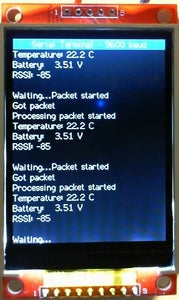
Output text messages sent using Serial.print from the other Arduino to the Terminal will be displayed. At 9600 baud the Terminal manages to keep up with the data flow.
Step 2: The Sketches and Libraries
The libraries and sketches needed are attached as zip files. The Terminal sketch is included as one of the examples within the Adafruit_ILI9341_AS library.
The Adafruit_GFX_AS library attached contains some significant speed improvements that permit drawing font 2 characters at over 1000 per second, this is needed to keep up with with a full speed 9600 baud rate. This version of the library requires the use of the ATmega328 processor (as used on UNO) since direct PORT access is performed. To use the library with other processors, such as the ATmega2560, the sketch will need to be modified to the correct hardware SPI pins and the following line must be commented out:
#define F_AS_T
within the "Adafruit_ILI9341_FAST.h" header file located in the Adafruit_ILI9341_AS library folder.
No changes are needed when using the ATmega328 based Arduinos providing the pins listed above are used.
A speed demo sketch has been included here, this is the one I use to test the speed improvements, it is an adapted version of a sketch that comes with the Arduino UTFT library.

Step 3: Operating at Higher Baud Rates
In most cases characters don't get lost at 9600 baud but it is a good idea to increase the serial Rx buffer from 64 bytes to 512 or 1024 bytes, especially if higher baud rates are used. The sketch does not use much RAM so even a 1024 byte Rx buffer leaves RAM spare.
To increase the serial buffer space the method described here works well:
http://www.hobbytronics.co.uk/arduino-serial-buff...
The TFT ILI9341 driver scrolls the display almost instantly, but it takes the Arduino about 13 milliseconds (ms) to erase a line on the display during the scroll process. In this time more characters may be arriving, so the buffer helps by storing the serial data until the ATmega processor gets around to taking more bytes out of the buffer.
The line erasure code in the sketch is optimised by storing the length of each line of printed text and then only over-writing that area, this means the worst case where 1 character is printed on every line it does not take 13ms to scroll and erase a line, but more like 1ms.
Step 4: Adapting the Sketch

Using the hardware scrolling feature of the display is not easy to understand, it is one of the more esoteric facilities the ILI9341 driver chip provides. The concepts of circular buffers and how the pixel y coordinate changes as the display scrolls will need to be understood, otherwise changes to the sketch are likely to give seemingly unpredictable results. If you are really keen then read the ILI9341 data sheet!
Just for fun I created a "Matrix" falling characters effect by scrolling the screen! Sketch is attached in case anyone may be interested... :-)
Attachments
Step 5: The Future...
Any updates or bug fixes to the code will be posted here, so come back and check for updates if you are having a problem.


