

Introduction: BLU-BOARD, Control Your Home With Blue Tooth!


Big thanks to the fine people at Hack-A-Day for sharing this with the world!
if you'd like to donate to the project: https://www.suprmasv.com/projects/167/blu-board
This project has been in the works for along time, three months if I reckon Correctly, but anyways, this device will allow you to control devices in your home, whether it be your homes thermostat or your lights it all can now be done over blue tooth with ease. so lets begin.
Step 1: Step 1: Sourcing Parts

you will need the following parts :
bareduino kit : $8.95
2 channel relay : $5.85
bluetooth module : $8.52
random header pins and sockets~$2.00
small piece of pcb~$2.00
programmer (optional) $9.00
enclosure (optional) $19.51
a led ~10 cents
Step 2: Step 2: Producing Main Board


first we must produce the pcb for this device, in this instructable im not going to go over how to etch a pcb, if you dont know, just google it, anyways i designed the pcb in inkscape and it is available for download here in a zip file.
EDIT: peter__s created a gcode file as well if you wish to mill the board. thanks peter!

Step 3: Populate the Pcb

solder up your components as the image shows, this should be relatively self explanatory at this point, just make sure that the chip has its notch pointing to the left and that the led has its long leg going to the a0 pin on the chip.
Step 4: Relay Controller Modifications

this next step is going to require you to use a header socket to replace the control pins on the relay module, this will require some de-soldering which can be tricky if youve never done it before . basically it should look like this when your done
Step 5: Header Construction


on the main board we have to use some extra long header pins to create a connection to the relay module, to do this cut a segment of header pins that is 4 pins long and push the little plastic piece to the end of the pins like shown in the photos and then push it through the board and solder it in place like so.
Step 6: Finish Populating the Board

now add the last two header connections to the board like so, and plug your new main board into the modified relay module.
Step 7: Upload Firmware

this step requires the arduino ide and the included firmware to make this thing operate, i designed this to work with the cp10102 uart tool for programming so you may need to make a special adapter to use a different programmer, but its fairly simple. when the board has its firmware the led should blink once when it turns on to let you know its alive and running.
Attachments
Step 8: Plug It In!

now you can install the bluetooth module by simply plugging it in as shown in the photo, after which you can power it up and use a bluetooth dongle with your computer to send it commands. the board should be listed as hc-06 when you scan for the device and you can use the arduino ide to send it commands, to control it send a 1 or a 2 to control the first relay and 3 or 4 to control the second relay.
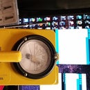
Step 9: The Case


this step is entirely optional but adds a nice finished product touch to it. to make it easy i had the case manufactured by ponoko and you can order one here
also i included the original svg file if you happen to be lucky and already have access to a laser cutter
Attachments
Step 10: Final Thoughts

it was a long time coming to getting this far to the release of this to the public but i just want to let you know i went through 5 different iterations of the main board to get it all working right, but in the end it was totally worth it

Finalist in the
Hardware Hacking

Participated in the
Make It Glow Contest

Participated in the
Workshop Contest


