

Introduction: Bike Trailer Conversion: Kid to Cargo (with 3-Axis Caster Hitch)


I have no car, and it's difficult to take large cargo on the bus or train, so I decided I needed a bike trailer. I've been getting around almost exclusively by bike for about seven months now, working on this trailer on and off during that time, and just recently completed it. I used it to transport moderately heavy loads two times in the week following its completion, as well as a few times since, and it has worked great! It makes my life a lot easier to be able to transport larger things than I can strap onto my bike's rack without having to ask for a ride from someone with a car, or carry them to the bus stop and through the train station.
This instructable shows how I went about converting a bike trailer given the materials available to me and the skills I had. You will probably have to modify the steps quite a bit unless you have exactly the same materials and tools. Nevertheless, I'll present what I did in as much detail as I can to make that easy for you.
The part of this instructable that's most likely applicable to your project is the caster hitch, which is described in steps 8–16, with steps 8–13 being the hitch itself and steps 14–16 being improvements. I also link to several other instructables about caster hitches in step 8, in case my version doesn't work for you.
In this instructable, many steps start with a photo of the end product of that step, for easy browsing.
Wheels Contest
I was planning to enter this in the Make it Move Contest, but I was too slow for that. Fortunately, a related contest came along a few months later! The electric skateboard would be a more convenient way for me to get to school (though I'd have to figure out how to add studs to the wheels for traction on the ice in the winter).
Homemade Gifts Contest
Another member of Protospace saw my trailer and commented that he'd like to make some for some homeless people he knows who get around by bike. I think a cargo trailer would be a great gift for anyone who gets around by bike but can't carry enough stuff, homeless or not.
Step 1: Find an Old Bike Trailer (or Jogging Stroller) and Take It to Your Workshop


Check garage/yard sales, your local classified ads websites, etc., for used bike trailers. I would lean toward ones with fabric that's wearing out or that are otherwise not in great condition, and leave the good ones for people with kids to buy.
In my case, I had been talking about wanting to build or convert a bike trailer for a while, and a friend soon found an old trailer and an old jogging stroller at garage sales. I took them home.
When I went to get them out to convert them, I forgot where I'd put the trailer, so I got out the stroller first, and took it to Protospace. I didn't have much luck figuring out how to convert it (though Tsanabe recently posted an instructable about converting a very similar jogging stroller to a bike trailer).
Later, I found the trailer, and took it to Protospace and started converting it.
Since then, I found a third old bike trailer at a garage sale a few blocks from home, and as I was buying it, the seller's next-door neighbor came home and offered me his bike trailer (lacking wheels) for free, so now I have a bit of a collection.
Step 2: Take Off the Fabric (optional)


Depending on how your donor bike trailer is made, you may have to cut off some or all of the fabric. I used a snap-off blade knife to do this. I also had to remove a few bolts and nuts to get some of the fabric off. (It was anchored to the metal rectangle on the sides by bolts, and was also sewn around the horizontal bar of the upper part of the frame, which I just unbolted and slid out.)
Save any retroreflective patches, buckles, and other useful things from the fabric, if you like.
Step 3: Find Something to Make a Platform Out Of


From seeing other bike trailer projects online, I decided on a wire rack for the cargo platform.
It seems to be the case that if you start a bike trailer project, and decide to use a wire rack, a suitable wire rack will soon show up for you to use (based on two other bike trailer projects I saw online, and my experience). I happened to find this one on the Protospace free shelf the same day I decided to use one. It fits perfectly and is very strong. It also seems to be rustproof.
It has some weird tapered tube things attached to its corners. I don't know what these were for; they seem to be to mount the wire rack on something. I decided to keep them, because they might be useful, and because removing them would create openings in the rustproof plating.
Step 4: Figure Out How to Attach the Platform


I decided to use some 2×4 pieces to mount the wire rack to the trailer frame.
The pieces I used are leftover pieces from the Protospace picnic table build this past summer. They are preserved wood, so they should last a while outside. When working with preserved wood, be careful to not breathe the dust—use both dust collection and a respirator, preferably. Fortunately, we got the central dust collection system in Protospace's wood shop installed and running a few months previously. Also, I had to make cuts in the wood, and the preservative is only at the surface, so I used some preserved wood sealant (specifically made for sealing cuts in preserved wood) that was also from the picnic table.
You can also use un-preserved wood, as long as you either paint it or take care to keep it dry (i.e. dry it off after every ride, and store it in a low-humidity place).
To make the pieces of wood fit on the trailer frame, I had to make some cuts in them. For the middle piece, I rabbeted both ends so that they'd fit over the sides of the trailer frame. (I later decided to add a second middle support for additional stiffness.) I did this on the sliding compound miter saw, but it would also be easy to do it with a hand saw and maybe a chisel or a sanding block for fine tuning. For the front and back pieces, I cut coves on the table saw, to fit over the round front and back tubes of the trailer frame. That step could also be done with a molding plane, or probably several other hand tools I don't know about. Of course, depending on your frame, you might not need to do that at all.
Step 5: Figure Out How to Mount the Hitch on the Trailer


The donor trailer had a towing arm, but I couldn't think of a good way to mount a caster to it. Its end was also not quite on the center line of the trailer.
I decided to add a wooden tongue to the trailer to mount the hitch. The tongue is crossed with the front piece of wood that supports the rack. I accomplished that by dadoing both pieces and fitting them together to form a cross half lap joint. I did that on the sliding compound miter saw and the table saw, but it could also be done with a hand saw and a chisel or hand plane.
Step 6: Add Stiffness


At this point, I noticed that if I supported the trailer at the tip of the tongue, the front of the bed dipped down, and the tongue/front support did not stay in line with the bed. I didn't get a photo of that, but in the second photo, you can see the opposite happening: the front of the bed is supported, and the tongue is sagging. I first attempted to remedy this by tightly zip-tying the front support to the wire rack, but it wasn't enough, and it would put a lot of stress on the wire rack when carrying a load.
I decided to use some angle irons to connect the tongue to the cross-braces, mainly because we had some lying around and it seemed easier than making a wooden piece to do the same job. I found two pieces the same length, held them up to the trailer frame, and marked where they needed to be cut out, then cut and filed them. I also made cuts in the wood (at a slight angle, because the angle iron isn't exactly 90°). I shared the cutout roughly evenly between the angle iron and the wood, so that both pieces retained enough material to be strong. I put the angle irons on the upper side of the wooden pieces of the frame for two reasons:
- Cutting into the top of the wood (where the wood will be in compression under load) is better than cutting into the bottom of the wood (where it will be in tension under load, and a cut will serve to start a crack).
- The attempted rotation of the tongue/front support under load will try to move the aft ends of the angle irons downward, and it's easier to prevent that by resting them on top of the wood than by strongly screwing them into the bottom of it. (This does require strong screwing into the top of the tongue/front support, though, but I guess I found that easier at the time.)
Then I just drilled into the wood and screwed the angle iron on. Now the tongue is very stiff and it supports loads well.
Step 7: Figure Out How to Attach the Hitch to Your Bike, and Build That


I wanted to have the hitch directly behind the rear wheel of my bike, because I don't like hitches that attach to one side of the bike frame (usually clamping to the chainstay and seatstay). To do that, I needed a frame to hold the hitch there. I built it out of more of the preserved wood, because I know how to work wood (not well, to be sure, but passably).
To attach the hitch frame to my bike, I bent some aluminium sheet into brackets to connect to some unused screw holes on my bike frame near the rear dropouts. I cut the aluminium with a bench-mounted shear, but hand sheet metal shears would work too. I bent it in a bench-mounted box & pan brake, but you could also bend it with sheet metal bending pliers. I smoothed the edge with a milling bit in a Dremel rotary tool. Then I drilled some holes in the brackets to screw and bolt them to the wood.
I then used transfer punches to transfer the hole locations to the wood, and drilled them. I installed the screws and bolts, using a large impact driver (with a long stack of sockets and adapters to connect the screw bit to it) for the screws. The screws have Robertson drive, which is common in Canada and works a lot better than Phillips when you need to use a lot of torque. The bolts squeeze the wood together around the screws—this will hopefully prevent splitting.
I connected the two side pieces of wood using a third at the back (which is where the hitch will mount), using long lag screws. I later added a deck screw to each side to keep the back piece from rotating about the lag screws. I also cut the front of each side piece at an angle, to not collide with the derailleur (for the right side) and for symmetry (for the left side).
Then I added diagonal braces, using angled cross half lap joints to the lower part of the frame, going up to the diagonal parts of my rear rack (Planet Bike Versa Rack). I cut the joints on the miter saw, with the depth stop set, making lots of individual cuts side-by-side. Then I smoothed the surfaces with a chisel. This would also be easy using a hand saw. I actually made the surfaces slightly slanted, so that the diagonal braces are angled inward as you go up, because they need to be closer together at the top to attach to my rear rack. I drilled holes through them and the bottom parts of the frame, with them clamped together, and then installed bolts and nuts to hold them together. The bolts and nuts needed washers, but the only washers I could find at Protospace were a bit too big for the bolts, so I 3D printed some adapters that have an ID appropriate for the bolt and a protrusion into the ID of the metal washers to hold them in place. That will keep the metal washers from getting off-center. The design was very simple to do in OpenSCAD (and would be just as simple in any other tool).
The tops of the diagonal braces need to attach to the rear rack. I cut slots in them with a hand saw and a round file. I also cut crossing slots in them, and drilled holes, for zip ties. Then some rubber from a popped inner tube goes between the wood and the rear rack's frame before it gets zip-tied on.
I also added some rubber to the aluminium brackets to cushion them against the bike frame.
A much better way to make a hitch frame would be to weld it out of metal tubes (the same kind of metal as your bike frame) and then weld that to your bike frame. I will probably do this eventually, because the wooden frame is a bit wobbly. The other bike trailer instructables that I link to in the next step give more ideas for attaching the hitch to your bike, as well.
Step 8: The Caster Hitch: Idea and Early Experiments


The first photo shows the caster hitch I built and which is described in the following five steps. It's shown with paint, a unified ring washer, and a knob—those improvements are in the three steps following the next five.
I got the idea for the caster hitch from some other bike trailer instructables, namely building a strong flexible bicycle trailer coupler by weblar and bike rack, panniers, adventures: 4 packs, trailers, and fun—step 4: adventure idea: bench transporter by mikerushford. Others that you might find more adaptable to your trailer include bike trailer hitch by campbesj7, bike trailer hitch by moaibob, jogging stroller / bike trailer hack / conversion by jrobie, welded bike trailer by venicafe, and flatbed bicycle trailer by Tsanabe (also mentioned up in step 1). It is very important to note that if you have a trailer with more than one wheel it will not be able to tilt as you lean your bike to the side, so your hitch needs to accommodate that with a free-spinning roll axis. That means three hinged axes (pitch, roll, and yaw). Two linked instructables, jrobie's and venicafe's, violate that rule—they both lack a roll axis. (Perhaps they intend their trailers to support their bikes, so they don't have to balance?) Conversely, if you have a trailer with one wheel, you should not include a roll axis in your hitch, so that the trailer leans with you when you lean into a turn. All of my trailers (so far) are two-wheeled, so I'm building a 3-axis hitch.
(The rest of this step is about my early experiments. What actually worked is in the next steps.)
I found some old casters at Protospace that were in such a condition that they couldn't really be used as casters anymore, and drilled out their axles to remove the wheels. I then tried to find a pin that would fit, but I ended up having to drill the holes larger to accept the pin I was able to find. I didn't want to offset the casters like mikerushford did, so I had to bend one caster's fork open a bit and the other's fork closed a bit. I couldn't get them bent evenly, and they rubbed on each other such that the pitch axis didn't rotate very freely.
The fourth photo and the eighth photo show using a bolt with a nut as the pitch axle. I don't remember for sure why I thought that was a bad idea and pursued the pin option instead—I was probably worried that the nut would unscrew while riding. (In my final hitch, I used a bolt and nut, but that's because that's what those casters used for their axles. That nut has a nylon friction element, so it stays on just fine.)
In the last two photos, the relative orientation of the casters is the same as that shown by mikerushford, and the same as I eventually went with in my hitch. In the third and fourth photos, I was trying out an alternative orientation meant to use both casters in compression rather than tension. However, in the fifth photo, you can see there's a ball bearing for tension as well as for compression, so the basic configuration (the last two photos, as well as the first) should be fine with these casters. (In my final hitch, I used the same configuration, but the new casters don't have ball bearings for tension. Nevertheless, it seems to work just fine and not be wearing out yet, probably because they have lots of grease.)
Step 9: The Caster Hitch, With New Casters, First Attempt (Don't Do This)


(This step is about another version that didn't work out. I again present it for educational purposes. It contains some information about the casters that's necessary for the later, working version, so I suggest reading it.)
With my experiments with the old worn-out casters not going well, I went to the hardware store and bought some new ones. As well as them being in better condition, using new casters means I can buy more of the same type when I need them for future trailers or replacements. These ones happen to have the same bolt pattern for mounting as the old ones, but that's where the similarities seem to end. They have bolts with nuts for the axles, rather than rivets, and the fork springs open when unbolted. They also don't have ball bearings for operation in tension.
The forks being springy means I wouldn't be able to fit one inside the other and bolt them together (and if I did, there would be a lot of friction between them). So I decided to use a square steel tube (which I found a scrap of in a bucket of metal bits at Protospace) to connect the two casters. (I originally thought of using a similarly-shaped piece of wood, because, while I'm not very good at woodworking, I'm even less good at metalworking. However, the metal tube turned out to be quite easy to work with.) I would drill two holes through it, one for each caster's axle. But it would have to be anchored rigidly to one caster, to keep the tube from swinging back and forth, and the trailer from surging (moving forward and backward relative to the bike when braking and accelerating), which is annoying and dangerous.
My first attempt was a failure. I got help from a friend to cut the tube at a 45° angle. We used an abrasive chop saw, but a hacksaw could also be used. I then drilled it with a hand drill and tried mounting it to one of the casters. It turned out that it wasn't rigidly mounted at all! (See last photo.) I don't know how I didn't see that coming. Having two places where it can rotate about the pitch axis like this (the unintended one shown here and the intended pitch axis of the other caster) will allow the trailer to surge. Also, I found it was hard to drill the hole in just the right location for the tube to rest perfectly against the caster fork. The concept of using a steel tube to connect the casters was promising otherwise, though, so I continued with it.
Step 10: The Caster Hitch, With New Casters, Working Version, Part 1


(This is the version of the caster hitch I recommend using.)
Undaunted by the failure of the 45° version, I came up with a new concept for the hitch tube. It would fit over the rim of the round part of the caster fork so it wouldn't rotate. This would make it even more important than in the previous version for it to be a perfect fit between the bolt and the crown of the fork. To achieve that, I decided to drill the holes a bit further away from the mating end than they needed to be, and file to fit.
This technique worked very well and I recommend you do the same. But don't do that yet—you need to do another couple of filing operations first, because they also impact the fit:
First, you will also need to file the mating end of the tube to fit the caster. The hub of the caster's vertical axis needs a cutout in the tube. This isn't a mating surface (because it will be rotating relative to the tube), so just file it so they don't touch. I found a large aggressive file in the drawer at Protospace that made quick work of this, and then cleaned it up with a round file. To fit over the fork crown rim, you need to file a notch in each side of the end of the tube. This is the mating surface, so make sure it fits well. (It's difficult when you haven't yet drilled the hole, because you have nothing to compare it to. Just try to get it so that it fits firmly without rocking side to side when you hold it such that the caster's wheel axis passes through the tube somewhere near its midline.) I used a round file to make a rounded notch in each side, and used a square to make sure they were the same depth.
Second, you might need to file your caster's fork. At the factory, they don't necessarily cut it perfectly straight across, because it doesn't matter in the caster's normal application. I was confused for a while why my tube wouldn't sit straight in the caster until I noticed this. I filed it until it was visually straight across, and this worked. The disadvantage to filing here is that you'll lose some of the galvanization or other rustproofing (such as paint), if your caster has any. (I noticed my caster starting to rust there once I started using it, and applied some primer to protect it.) If you want to preserve the caster's coating, you can file one notch in your tube a bit deeper to accommodate the slant in the rim.
Go through the photos and read their notes for more in-depth instructions.
Step 11: The Caster Hitch, With New Casters, Working Version, Part 2


Now it's time to do the thing mentioned in the previous step where you drill too far away and slowly file the hole closer until it fits. You just need a small round file. The far side of the holes doesn't matter. The holes can be too large there without causing a problem, but if their close side is too close, that's hard to fix without welding or starting over. So drill a bit too far along the tube from the mating end, and then start filing it and keep checking frequently whether the caster's axle bolt fits through.
Go through the photos and read their notes for more in-depth instructions.
Step 12: The Caster Hitch, With New Casters, Working Version, Part 3


The tube now needs another hole through it, parallel to the first, for the second caster's axle bolt. This one will be allowed to rotate, so the end of the tube needs to be clear of the top of the caster's fork. This means that there's no need for precision here; just drill holes for a slightly loose fit in approximately the right location.
I used a square again, in conjunction with a scriber, to mark how far along the tube I wanted to drill, as well as approximately halfway across the width of the tube. (It doesn't matter exactly where the holes are, as long as they're reasonably closely aligned from one side of the tube to the other,* so be careful with how you use your square, but don't bother to set it precisely.) A straddle square would also work well, if you have one.
Once you have your 'crosshairs' scribed or otherwise marked, use a center punch at that location. Then drill for clearance on the shoulder of the axle bolt.
If the holes aren't aligned well from one side to the other, use a small round file again to align them. Don't forget to deburr them. Then check how it fits with the caster.
Go through the photos and read their notes for more in-depth instructions.
*Unless you're making a unified ring washer (step 15), in which case it will be easier to design if the holes are exactly on the midline of the tube.
Step 13: Mount the Hitch


Hold your hitch up to both your trailer tongue and your hitch frame (one at a time) and measure to be sure it's centered (if you care about that). Then mark and drill the holes. Install with bolts and nuts. Now you can tow your trailer!
Step 14: Paint the Tube


Unless you live in a very dry place, the tube, being steel, will rust if left exposed. Therefore, we need to paint it.
First, rough it up a bit using files, sandpaper, and/or abrasive blasting. I used all three. Then apply some metal primer and let it dry. Follow that with a couple of coats of rust paint. Don't forget to paint the inside.
You can use the holes to suspend it while it dries.
Some chipping or abrasion of the paint is to be expected, and you'll probably need to scrape the paint out of the holes so the bolts can fit. Despite that, and riding in the winter with lots of snow and slush, I haven't noticed significant rust on the exposed bits past the first week or so, prior to painting (last four photos), when it rusted a bit and I filed the rust off.
Step 15: Add Some Washers


The caster forks rubbing on the tube will quickly wear the paint off, and there's some sideways looseness even when the nuts are tightened all the way. I would have put on regular mass-produced metal washers, but Protospace didn't have any the right size for my casters' bolts (M6). So I modeled a washer in OpenSCAD and printed several of them, just as I had for the hitch frame on my bike.
I started with four individual circular washers. I used spray adhesive to hold them onto the hitch tube. These worked okay, but they fell off despite the adhesive and were difficult to hold in place when reassembling the hitch. I kept them for the bike side of the hitch, because I rarely disconnect that side, but replaced them with a "unified ring washer" for the trailer side. This stays on by friction alone and is always perfectly aligned to put the bolt through. The print didn't come out perfectly, but it works just fine. If I were to print it again, I would just make the whole thing the necessary thickness of the washers, rather than having circles of that thickness, and then there would be no problems with the transition.
Step 16: Ergonomize the Hitch Some More

For the first couple of rides I did with my trailer, I used the caster's nut as it came, using an adjustable wrench. This was inconvenient, because I had to hold the bolt, nut, and wrench in precise alignment while also supporting some of the weight of the trailer and cargo with my hand. Also, because I hadn't developed the unified ring washer yet, I had to hold both washers up too (one at a time as I inserted the bolt). It was extremely inconvenient, especially in the cold.
So, at the same time as I created the unified ring washer, I added a knob to the bolt. I just did a search on Thingiverse for 'nut knob' and found several that would work. I went with taposk's M6 nut knob, but you can use whichever one you like, as long as it's parametric/customizable or designed for your size of nut. After hammering the nut into the knob, I can now hitch and unhitch my trailer with ease and no wrench, even with gloves on.
I thought of adding a knob to the head of the bolt too, to help orient it so that its shoulder points fit into the hole, but I didn't get around to that, and I can orient it okay with my fingers.
Step 17: Attach the Bed and Taillights


I used zip ties to attach the wire rack to the metal frame of the trailer. The wooden parts of the trailer aren't really attached to the metal frame or the wire rack at all, but just sandwiched in between. This turns out to work really well, in my case. It helps to have the angle irons attaching the wooden parts to each other. The rear support piece isn't attached to the angle irons, but it's clamped well enough between the metal frame and the wire rack, and it has grooves for the wire rack's perimeter wire, so it won't slide sideways.
I started with some releasable zip ties, so I could easily take the rack off and put it back on without wasting zip ties. However, I didn't have enough of them to hold it on very strongly, so I replaced them with a lot of permanent zip ties when I was sure I was ready.
I bought a set of battery-powered red-only Christmas lights and attached them to the upper frame of the trailer to serve as taillights. They do a pretty good job. I only taped the battery box on, though, so I'll have to redo that when the batteries die.
Step 18: Take It for a Test Ride


Take your trailer out for a test ride, with no or a small load. Watch it carefully to see if anything breaks.
(I didn't actually do that. I loaded it up with a heavy load and went all the way home (~8 km/5 mi). Luckily, it was fine. Do as I say, not as I do.)
Step 19: Transport Cargo, and Impress Your Friends


I don't have pictures of the first load I carried with it (or the second) but I do have video, which I recorded to prove to my disbelieving friends that my bike trailer was done (well, done enough to use—it can always be improved).
The wire rack makes it really easy to strap things down using bungee cords or ratchet straps. I carry a long hookless ratchet strap in my pannier, along with a jar of bungee cords on top of my rear rack (held in place by my panniers' linked handles). I also carry a small polyethylene painting dropsheet and a large plastic shopping or garbage bag or two to protect loads from precipitation and dash.
First few loads carried:
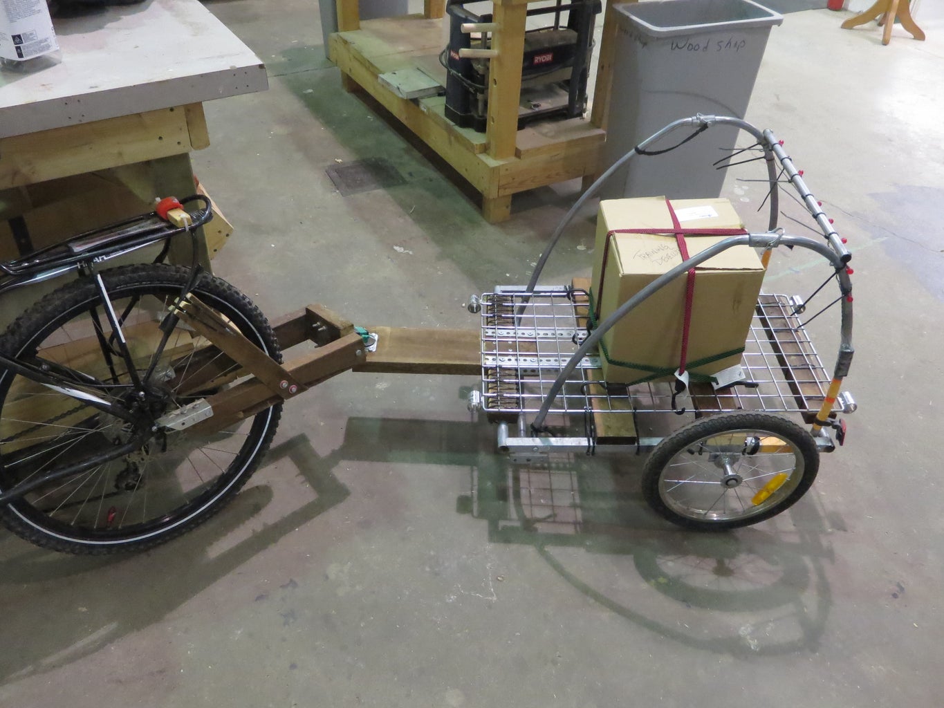
- Nuclear Data 62 (pictured in step 17) (in a black bag for protection from snow) with the collapsed jogging stroller strapped on top and a few other things strapped on as well, 8 km/5 mi (start of trip shown in video)
- HP 7210A pen plotter, 12 km/7.5 mi (no photo/video, but I'll try to remember to get one when I transport it next)
- Mobility scooter chassis and kids' electric kick scooter, 8 km/5 mi (photos)
Pro tip: If you turn the bike side of the hitch upside-down (so the tube points up rather than down) before hitching the trailer, the front of the trailer will be a bit higher, leaning the trailer back, and the load on the hitch (and the weight on your bike's back wheel) will be a bit less. Might be helpful for balancing.
Step 20: Possible Improvements
Here are some ways I want to improve this trailer in the future:
- Remake the frame out of welded aluminium. I need to learn welding first. Fortunately, Protospace now has a great welding curriculum, thanks to several members who are welders, but I haven't taken the courses yet.
- Add a dashboard (in the horse-drawn vehicle sense) over the upper opening of the hitch frame.
- Add a piece of flexible dryer exhaust hose over the hitch, to further protect it from dash and precipitation.
- Add a folding front leg or wheel, as well as a handle at the back, so I can disconnect it from my bike and use it as a shopping cart.
- Remake the trailer tongue in a shape similar to a Sukhoi fighter, so that I can put the hitch on the underside of the tongue, both for compressive loading of the casters and in support of the previous improvement (reusing the caster as mentioned in the third-last photo of step 7).
I hope you found this instructable informative. If I missed anything, or if something is unclear, please let me know.

Participated in the
Homemade Gifts Contest 2017

Participated in the
Epilog Challenge 9

Participated in the
Wheels Contest 2017


