

Introduction: Build a Better Raspberry Pi Power Button


It's very easy to make a Raspberry power-off or shutdown button. There are lots of such projects on the web and a few here on Instructables, but none of them (that I can see) tell you when your Pi has actually finished shutting down and hence it's safe to pull the power. In fact they don't even acknowledge that the button-press has been seen.
There are projects, too, to restart a Pi that has been shut down, but neither do these give you any visual feedback.
But who needs such a button? If you're a bit of a nerd like me, or even just an aspiring nerd, you can always log in to your Pi locally or over the network and type sudo shutdown -h now. But if you're building a project for non-technical users, that just won't do. True, you can nearly always get away with just pulling the power cord, but note, I said nearly always! Everybody's luck runs out sooner or later. I had an SD card die on me only last week, though I'll never know whether or not it was really due to an abrupt power loss.
In my case I needed to add a power button to a Pi we use as a midi sequencer for recording and playing back hymns and songs in church, for when we don't have a live pianist available. I can always type the shutdown command but I need to de-skill it for when I'm not there.
My intention here is not to give you a finished product, complete with beautifully 3D printed case, like so many other Instructables. Everybody will have a different use for it or want to incorporate in their own project. Rather, I'll set you up with the technology that you can add to your project, whether it be a media centre, an IoT device, or anything else.
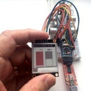
(In the video I'm demonstrating it with a Pi Zero v1.2 and a monitor I made from a repurposed laptop screen and a controller from the Far East.)
Step 1: The Design

This is what my power button will do for you:
- When the Pi is running, a LED is lit continuously. If it's shut down manually the LED goes off only when it's safe to unplug the power.
- Whilst running, if you press the button for at least a second a shutdown is initiated and the LED flashes off for a quarter of a second every second until it's safe to unplug the power.
- From a shutdown state (if the power hasn't been removed), pressing the button starts it booting and flashes the LED on for a quarter of a second every second until it's booted up. (It may take a little longer until all services such as ssh and vnc are running.)
The components are very cheap. All you need is:
- ATTiny85 (Arduino-compatible chip)
- 3 resistors: 2 x 330Ω and 1 x 10kΩ
- 1 LED - I suggest green or blue, but it's your choice
- breadboard and jumper wires, or stripboard, or however you want to build it.
Step 2: How It Works

As with all Pi power buttons, this one pulls a GPIO pin to a low state to signal a shutdown request to a helper program running on the Pi. I used GPIO4 (pin 7) but you can use any other pin.
The only way to tell that a Pi has completed shutdown is by watching TxD pin 8, which then goes low. This depends on the serial console being enabled, which it is by default. In fact TxD will regularly go up and down while it's being used as a serial console, but it will never go low for more than around 30mS at a time, even at the slowest common baud rate. It can still be used for a serial console as we just passively watch it.
To reboot, we need to briefly pull SCL1 (pin 5) low. This pin is used by any I2C devices (including my midi interface), but after initiating the boot we leave it alone.
Most of the complexity is in the Arduino sketch which we load into the ATTiny85. This implements a "state machine" - a very useful and powerful way of coding any problem that can be represented by a number of "states". A washing machine works in just the same way. The states represent the stages in the wash cycle, and each one defines what the machine should be doing at that point (motors or pumps to be run, valves to be opened or shut) and what sensor inputs (temperature, water level, timers) determine when to move to the next state and which next state to choose.
The hand sketch is my first draft of a state diagram, showing all the state transitions. This is just to show you how you can initially plan your states and state transitions - it may not be completely accurate as that was before I started debugging.
In our case, we have 6 states which I've called OFF, BOOT REQUEST, BOOTING, RUNNING, SHUTDOWN REQUEST, and SHUTTING DOWN. (After SHUTTING DOWN it moves back to OFF.) These are identified by comments in the sketch, and for each, further comments say what it should be doing and what events will move it to another state.
The helper program running on the Pi is just a little more complicated than for most shutdown buttons. It responds to a long low pulse on the GPIO pin by initiating a shutdown, but it also responds to a short pulse by itself briefly pulling the GPIO pin low. This is how the ATTiny85 can tell that it's running and so can move from the BOOTING to the RUNNING state.
Step 3: Building a Demo Prototype


For demonstration purposes you can prototype it on a solderless breadboard as shown but I've also given you the schematic so you can work out your own layout using stripboard or a custom PCB, perhaps part of a wider project.
Step 4: Programming the ATTiny85
The Arduino sketch and the helper program are attached to this step. In your Arduino sketches folder, create a folder called PiPwr and copy the file PiPwr.ino into it. Launching the Arduino IDE you will now find it in your sketchbook.
There are several ways of programming an ATTiny85. If yours has a bootloader installed you can use an ATTiny85 development board costing only a few pounds. This connects to your PC via a USB port. I used a Hidiot which is essentially the same but with a prototyping area.
In the Arduino IDE under File - Preferences, add
http://digistump.com/package_digistump_index.json
to the Additional boards manager URLs.
Under Tools - Board you should now see a number of Digispark options. Select Digispark (Default - 16.5MHz).
If your ATTiny85 doesn't have a bootloader (or you don't know) then you can get an AVR ISP programmer for a few pounds. Or you can use an Arduino Uno or cheaper Pro Mini or Nano as a programmer. Google for "arduino as isp attiny85" (without the quotes) for instructions.
If you want to modify the sketch you will find it fully commented and hopefully easy to follow. For debugging it's much easier to use an Arduino Pro Mini or Nano. Uncomment the serial.begin() in Setup and the print statements in loop() in order to see the steps it goes through using the serial monitor. There are alternate pin definitions in the source, commented out, for a Uno, Pro Mini or Nano.
On your Raspberry Pi, copy the file shutdown_helper.py to folder /etc/local/bin and set it as executable with the command
sudo chmod +x /usr/local/bin/shutdown_helper.py
Now edit the file /etc/rc.local with your favourite editor. (You will need to do so as root.) Before the last line (exit 0) insert the line
nohup /usr/local/bin/shutdown_helper.py &
Reboot, and the helper program will start automatically.


