Introduction: Build a CNC Router
Hello, it has been a long time since I read instructables and this is my second one. I assume that I will not enter in every details but if you need more, that would be a pleasure to add them :-) However, you will find every plans, STL files and main indications to build the machine.
Like every maker I enjoy create and develop new ideas that would help all of us in our everyday life. I don't have access to any workshop, that's why in addition to my 3D printer I started to develop an affordable CNC machine that everybody can easily build with very simple tools. This way I would be able to make the stuff I want!
When I started I had few aims :
- cost < 550$ all inclusive
- Simple design
- Good looking
- Dust protection
- Require only simple Tools : a drill, a dremel, jigsaw / handsaw
- Require 3D printer or at least beeing able to access one.
With that in mind, I started to draw some sketches and after a few days I came up with the main idea. The CNC would be closed on the side with the possibility to add a futur plexiglas Hood on the top. All the electronic would be on the back.
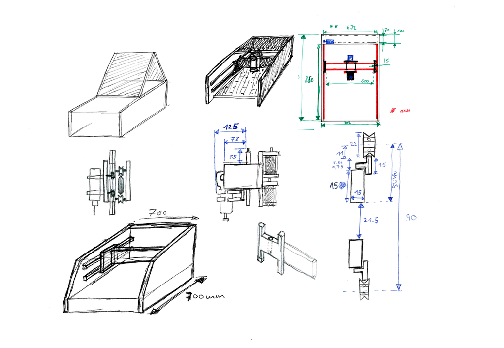
Note : some parts that should be 3D printed are in aluminium because I had the opportunity to make them during an internship in my studies.
Step 1: Required Parts
Bought in DIY store :
- 15mm thick birch plywood. See the dimensions according to the plans.
- 600x570mm 10-20mm thick MDF cutting bed
- 8x 1m aluminium T profil (see the PDF plan)
- 142x Wood screw length 22 to 30 mm
- 8x M4 Phillips flat head 25mm length
- 8x M4 secure nut
- 32x M5 hex head screw 35mm length
- 32x M5 hex head screw 16mm length
- 32x M5 secure nut
- 20x M5 nut
- 44x M5 washer
- M5 1m threaded rod
- M8 1m threaded rod
- 6x M8 secure nut
- 6x M8 nut
- 20x M8 washer
Bought on Ebay :
- 16x V-groove bearing
- 5m GT2 timing belt 6mm wide, 2mm pitch
- Closed timing belt 280, 6mm wide, 2mm pitch
- 2x Holder for GT2 timing belt
- 3x GT2 timing pulley 6.35mm bore (for stepper motor) (also 3D printable)
- 1x MR148zz bearing for threaded rod on Z axis
- 1x GT2 timing pulley 8mm bore (also 3D printable)
- 2x GT2 timing pulley bearing 5mm bore
- 1x 300mm Lead screw axis for Z axis
- 1x Power supply socket plug
- 1x Power supply 24V 15A
- 8x 608zz ball bearing Dint 8mm
- 3x Nema 23 stepper motor 270oz.in, 3A, model 23HS8430
- 3x stepper motor driver TB6560 3A
- 2 meter each, 4 colors 22AWG wires
- 20x 684ZZ bearings
In addition you will need :
- 1x router, I used a Makita RT0700C
- 1x Arduino uno
- bits for the router
Step 2: Wooden Plank
As almost every plank is square, I went to the DIY store and asked for wooden plank with the correct dimensions for the small ones. The bigger ones I did myself with a jigsaw but order it directly to the DIY store gives better results.
I recommend you to be specially precise with the wooden stick for the X axis and the drill holes. As you will see, some plank have oblong (long holes). Their purpose is to adjust bearings' positions during the assembly. I made them by drilling multiple holes and then by using a file as you can see here :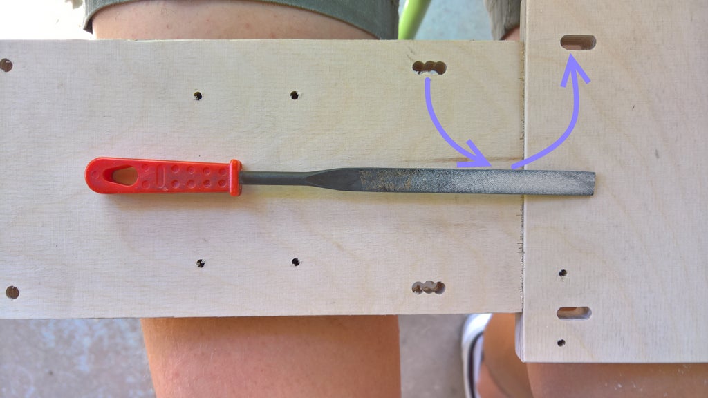
You will find a set of plan bellow
Step 3: Case and Y Axis
I recommend you to precisely assemble the X Axis rail. It has to be as horizontal as possible with a equal distance between the two all along the rail. I recommend to use 6 to 10 screw between the Case_bottom and the Case_side. 3 to 4 between the Case_side and the Case_insideBack / Case_back
Note : the schematics with colors of the inside of the case indicates the height of the rails.
Step 4: X Axis
A lot more screw to come! I recommend to use 6 wood screw between the two Axis_X_main. 6 for each Axis_X_TProfilAlu and 4 for each Axis_side. Start by assembling the wood parts and then the aluminium profils. I did not do that and it wasn't easy to be precise
Step 5: Z Axis
The bigger bearing near the motor will be used for the timing belt along the X Axis. When you screw the Axis_Z_TProfilAlu on the Axis_Z_Rail, make sure that the screw does not protude from the surface otherwise the bearing will touch them.
Mount the router support : Use the 3D printed parts :
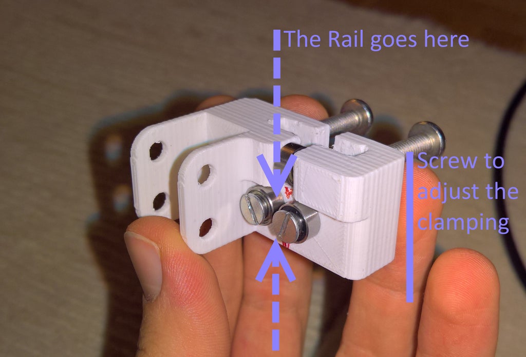
With the Router holder they go like this : (drill the holes with 3d printed parts in place if possible)
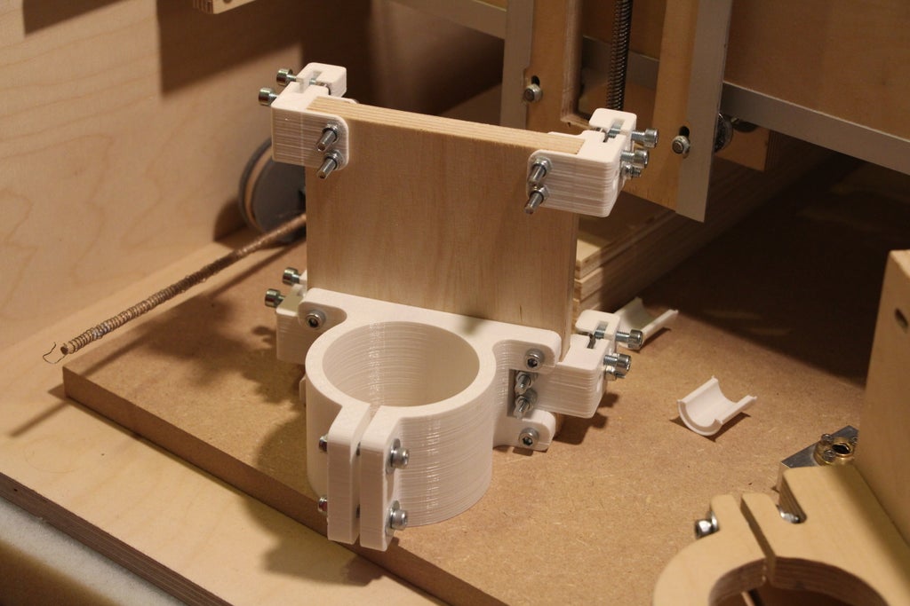
STL files bellow
Step 6: Assembly
Now it is the time to put everything together! The case, X, Y and Z Axis.
General Remark :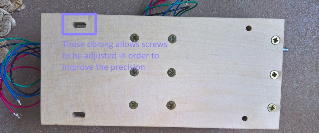
Z Axis
First of all, mount the X axis on the Z axis. Assemble both with M5 nut and threaded rod of 90mm long.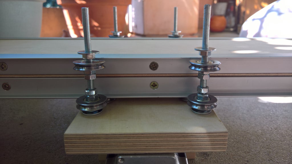
Between the two bearing must be placed two 3D printed parts to remove imprecisions. They hold together with a zip tie. You will find several version of it in the .zip bellow because the distance between the two bearing varies from 26mm to 27mm.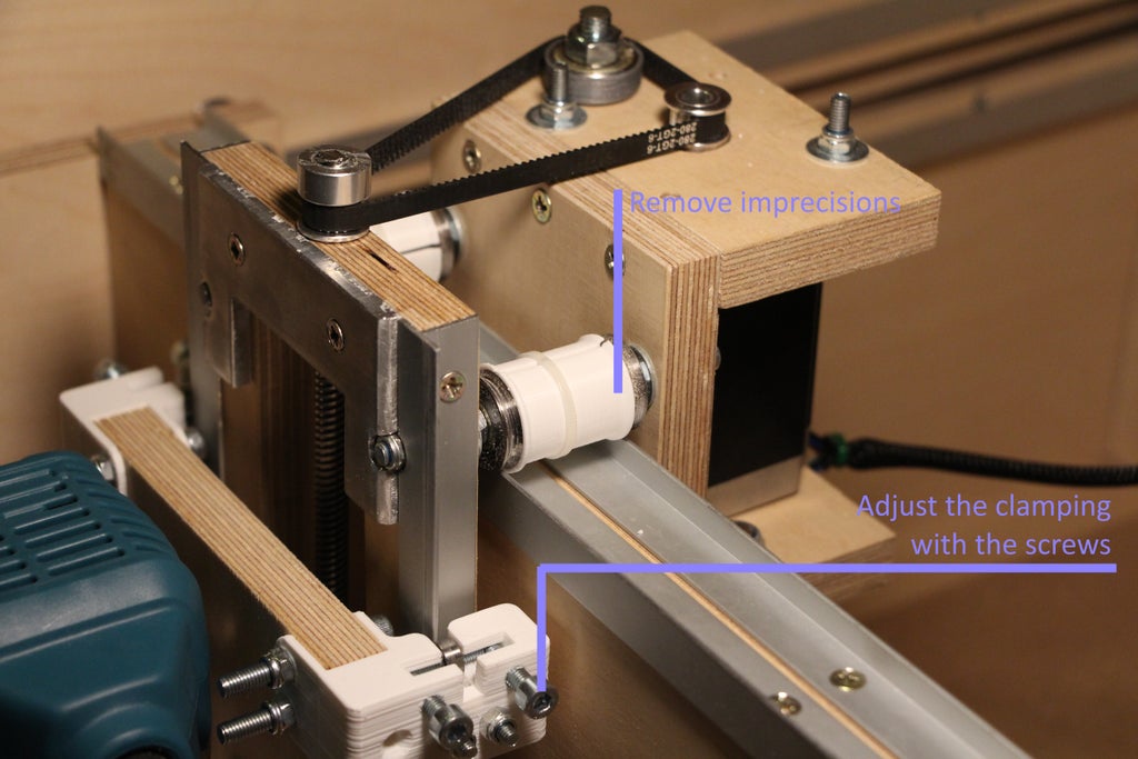
Add the Z axis threaded rod with the pulley (that can be 3D printed). The closed timing belt is stretched with a bearing. You may have to add a custom 3D printed ring to keep it in place.
Custom 3D printed pulley on thingiverse
To mount the part that hold the router (Makita RT0700C actually), use the 3D printed part (which is in aluminium here). Place it in the threaded rod and screw it with M5 hex head.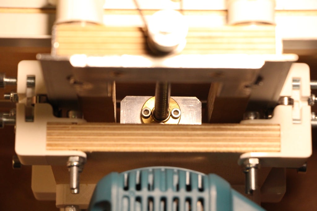
X Axis
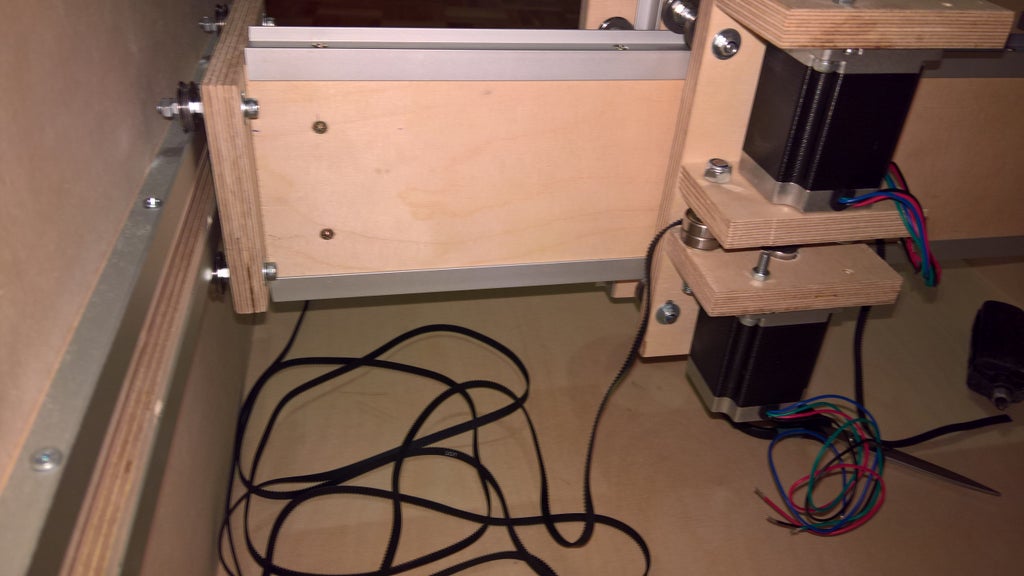
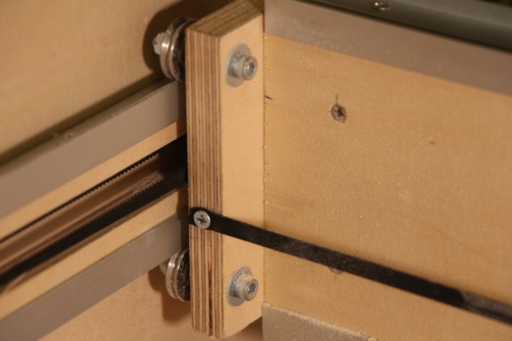
On the back of the X axis, I fixed the timing belt with a wood screw. This is probably not the best idea but it works. Maybe it would be great to add a washer. This timing belt go through the Z axis on the bearing and the motorised pulley.
Y Axis
The Y axis move the X axis from back to front. That's why we will put a timing belt between the two rail (as shown above).
First attach the belt of around 140cm (mesure it!) like that : (and one on each side)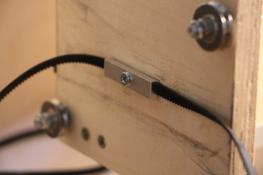
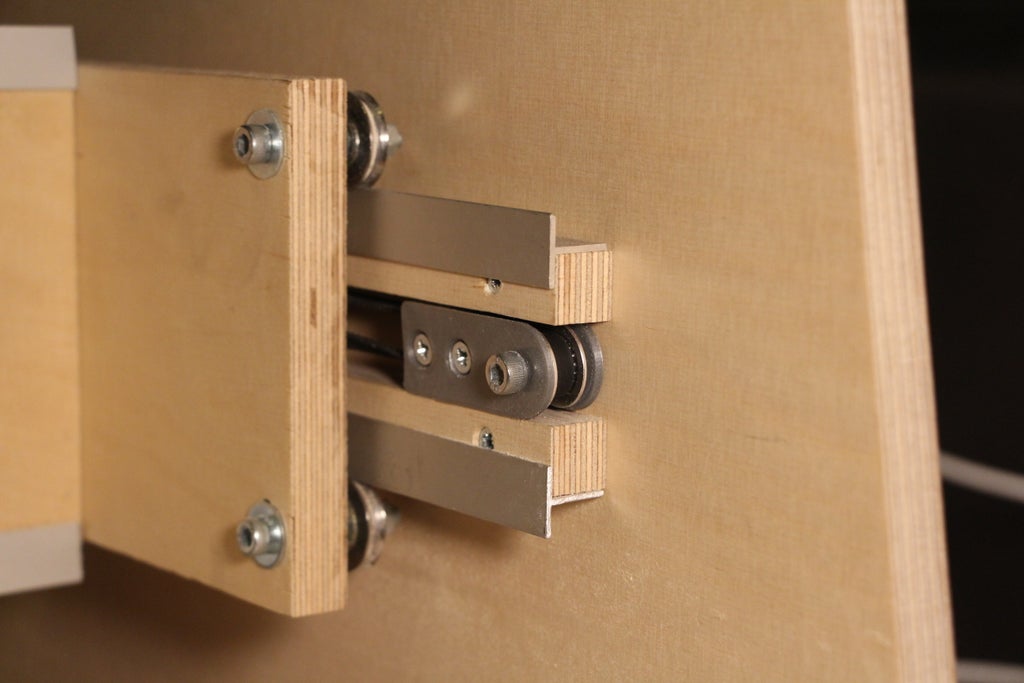
On the front end, the belt rotate arount a free pulley as shown bellow.
Note I use both aluminium and 3D printed version, one on each side.
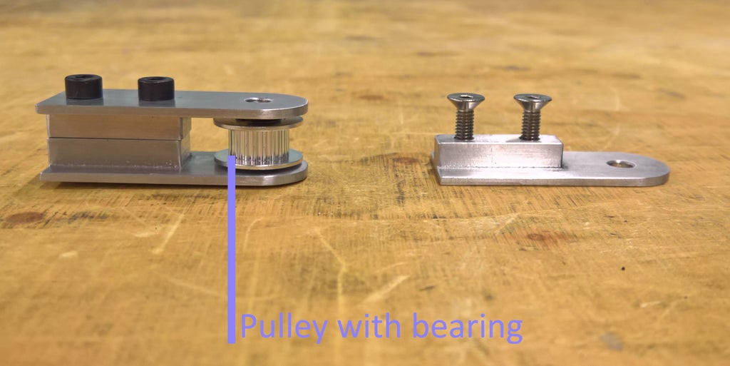
Mounted with two wood screw and a M5 screw for pulley, it looks like this :
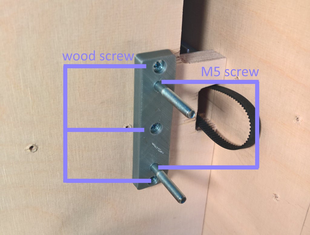
On the back, there is a system that connects the two belts to one stepper motor through a shaft. The shaft is a M8 threaded rod but you can use whatever you want but it is cheap and do the job. It rotates in 3D printed parts that can ajdust the belt's tension. The first part is mounted with 2 wood screw and two M5 screw that will enable the second part to connect to it and ajust the tension. The wood screw prevent the M5 screw to rotate because they tight the plastic.
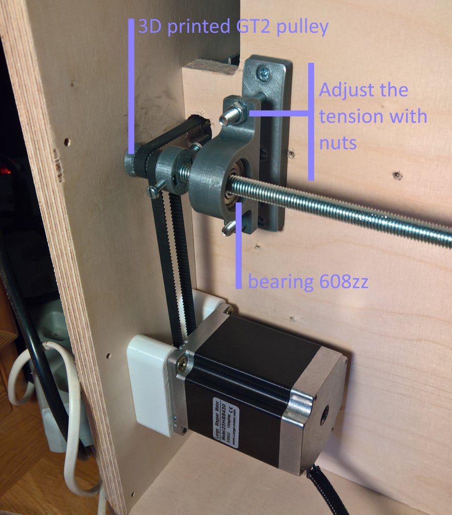
Then the second part is mounted as well a the support for the stepper motor
Now everything should be in place, let's connect everything with the electronics!
Step 7: Electronics
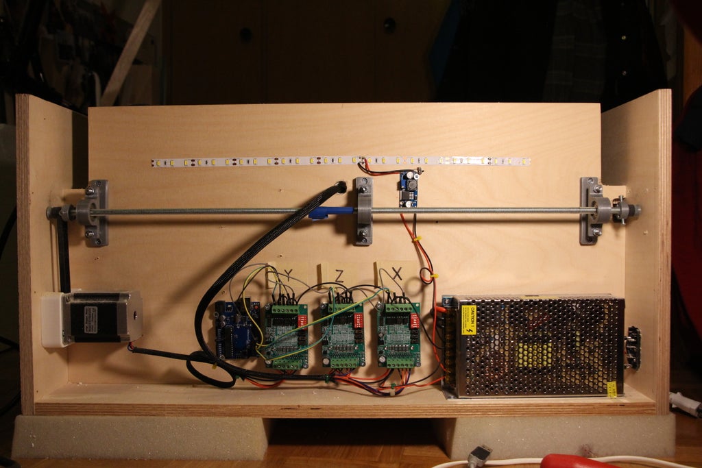
A cnc machine require only a few electronic components :
- Power
- Stepper driver → TB6560
- Gcode interpreter → Arduino uno
I will be using GRBL 0.9 with is an Arduino sketch available here. To upload it, simply follow the instructions on the website. It is very easy. It only require to upload a single sketch. Then connect the three stepper driver to the arduino by following those those images.
Note : I don't know what are the switches on the stepper driver for.
Note 2 : You will have to setup GRBL once it's on the arduino. It's important that 1mm in the code correspond to 1mm in reality. Everything is explained on the website.
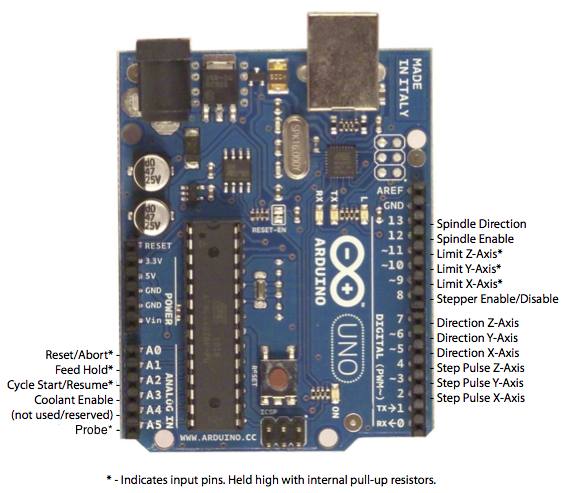
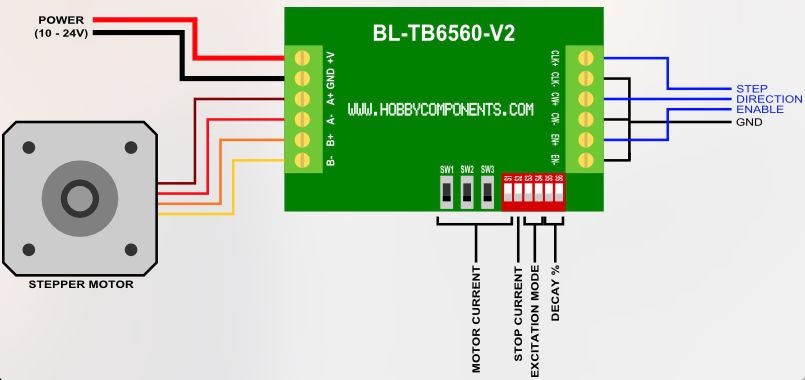
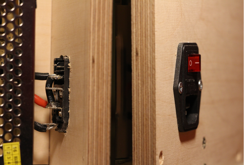
Then Power the stepper drivers with the power supply. I also used a plug socket with an interrupter. The arduino will be powered by the computer.
I decided to add some LEDs that light up when the machine is on. It requires a simple step down voltage converter and 40cm of white warm LED strip :-)
Step 8: Make It Alive!
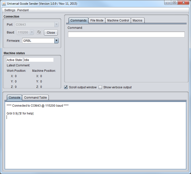
Now that the electronics is done and that GRBL is on the arduino, our cnc understand Gcode with is a machine language that tells when the motors have to move basically. We will use Universal Gcode Sender to setting it up. Here is how we are gonna do it :
- First plug in arduino to a computer with Universal Gcode Sender installed.
- Launch it.
- Set baud rate to 115200 and select Firmware GRBL.
- Clic Open.
- This is what you should have :
Then configure GRBL with the help of those instructions. On the Machine Control tab, we can move the three axis and see if it works!
Now let's test it with a pen :
Well that looks great! How does it go with plexiglas ? Not that bad
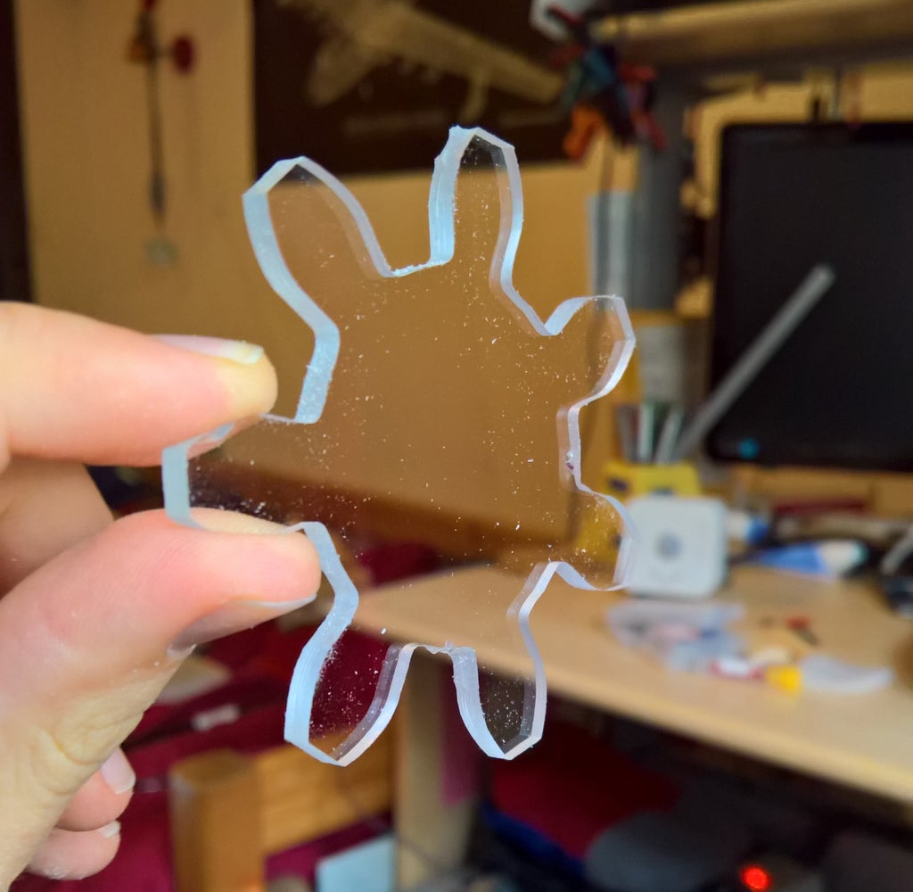
 For that I used Easel which is a free online CAM and CAD software developped by Inventables. It has built in GRBL support and work really well.
Then I tried to cut Birch wood and poplar wood and this is what it looks like :

Step 9: Conclusion and Future Improvements
Now that the machine has been running a few project, here is what I can say :
Great Points :
- Affordable ( < 550$)
- Simple design, easy to build
- Dust protection
- Great precision on Z and Y axis
- Nice looking
Improvements to bring :
- Reduce noise due to the vibrations of the stepper motor ans the router in the case. The case act as a crate of resonnance. I have to add a layer of cork or rubber between the motors and the case. I expect it will help dramatically. Eventually replace the router by a spindle which is way quieter.
- Increase precision by improving linear motion on X axis with a similar design as on the Z axis.
- Simplify the design with more 3D printed parts for more precision and an quicker assembly.
- Add a prexiglas hood for more dust protection
I hope you appreciated this project. In the following month (since January 2017) I will continue to work on this to improve the design and get better results!
See you next time!
PS : if you have any questions, it will be a pleasure for me to answer
UPDATE 2018 :
I suggest you not to make the same mistake as I did with my custom rails and go directly with a linear rail guide on each axis. Their prices dropped significantly on eBay or on aliexpress and they are now very affordable. It's harder, durable and easy to mount. Cheers!

First Prize in the
CNC Contest 2016

Fourth Prize in the
Design Now: 3D Design Contest 2016

Participated in the
Epilog Contest 8


