

Introduction: Build a PDK (Pocket Development Kit)


It's nice to be able to work on projects while on the road. This kit lets you carry an entire dev kit in your pocket.
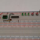
This instructable will show you how to build any of several different types of development kits (dev kit) which will all fit in your pocket. In the lower-left corner of the above photograph, you can see an Arduino compatible PDK. If you are familiar with the Arduino, you may recognize the Arduino IDE (Integrated Development Environment) on my notebook on the right side of the photo. We will discuss this one, plus several others, all of which can be inexpensively and quickly made.
Step 1: Select Your Microcontroller

For this kit, you will need to select a microcontroller. There are many controllers available, but the important thing, the thing that makes this kit work, is that the controller needs to have a bootloader preloaded.
Now, you are going to ask: "What's a bootloader?" Go ahead and ask... Well, a bootloader is simply a program loaded into a special section of the controller's program memory, called the bootloader memory. It's purpose is to allow you to download application programs through the serial port. When your application comes in over the serial port from the Integrated Development Environment (IDE - http://en.wikipedia.org/wiki/Integrated_development_environment), the bootloader then stores that into the main part of the controller's program memory. Once that is done, the bootloader allows your application program to run each time the microcontroller is reset, until you want to download another application program. What makes this so vital to our PDK is that there is no need for a microcontroller programmer (at least once you have the chip with the bootloader.)
There are several different bootloaders available, however we will just focus on a few.
Parallax is the company that got me going with microcontrollers, back in the '90s, with their BASIC Stamp (http://www.parallax.com/tabid/295/Default.aspx.) This is pictured at the top in the picture. The Stamp IDE will establish a link with the Stamp controller and download your application over the serial port. The Parallax Propeller will also work here, but it will take a lot of precious space.
In addition to Parallax, Atmel produces many different microcontrollers; many of them with bootloader sections in their program space. In the photo, you can see an Atmel AT-tiny2313 microcontroller. MCS Electronics (the publishers of BASCOM-AVR - the most powerful BASIC language for Atmel's AVR family) has a bootloader for most of the AVR microcontrollers. You can burn that bootloader into your choice of AVR and then use that chip for this kit. MCS Electronics offer a trial version of their BASCOM-AVR which includes that bootloader (http://www.mcselec.com/index.php?option=com_docman&task=cat_view&gid=99&Itemid=54 - click on the demo version link at the bottom of the page.) The IDE for this would simply be the BASCOM-AVR environment itself.
Many people have heard of the Arduino controller (http://www.arduino.cc/.) This open-source hardware board is taking the control-systems world by storm. It seems like nearly everyone and their dog are using the Arduino for something (Hack-A-Day is currently at 853 articles involving the Arduino - http://hackaday.com/category/arduino-hacks/.) While the full Arduino includes additional circuitry which makes it unweildly for this project (unless you produce your own PCB, which is certainly doable - https://www.instructables.com/pages/search/search.jsp?cx=partner-pub-1783560022203827%3Anpr2q7v5m6t&cof=FORID%3A11&ie=ISO-8859-1&q=pcb,) there is a stripped-down version which uses basically just the chip (see http://todbot.com/blog/2009/05/26/minimal-arduino-with-atmega8/.) This will let you use Arduino sketches, with the Arduino IDE, on your PDK.
Microchip (the producers of the famous PIC line of microcontrollers) also has many chips with bootloaders. For those of you interested in the PIC chips (or any other types of microcontrollers), you can do an Internet search for your favorite chip and "bootloader" for more information.
Step 2: Gather Your Parts

Now that you have chosen a microcontroller with a bootloader pre-installed, you need to gather all the parts together.
The parts that you will need for this project are:
1) The preprogrammed microcontroller that you chose in Step 1
2) An Altoids box (of course ;) ) - I also used an old Whitman's Chocolate Sampler metal box for my Arduino PDK
3) A couple of mini-breadboards.
4) A USB-to-TTL converter.
5) A piece of antistatic foam.
6) A miniature SPST NO (Normally Open) pushbutton switch.
7) Some miscellaneous parts to use for your projects/experiments.
Step 3: Fill the Box


Take the Altoids box and open it up. Take one of the mini-breadboards and remove the wax-paper backing from the foam tape on the bottom. Carefully attach this to the inside of the lid (we don't want to mount them to the outside of the lid because then your circuits will not be protect while you are transporting the kit.) You need to be careful to allow room for the sides of the bottom part of the box, or you won't be able to close the kit. The adhesive on these things is pretty strong - they do not want to let go once they touch the Altoids box, so mount them with care.
Once the breadboards are mounted to the inside of the lid, cut the antistatic foam and place it into the bottom of the Altoids box. You will probably want to add rubber cement or something else to glue it down into the box to keep it from falling out. The purpose of this foam is to hold your components in place so that they do not smash against your circuit when the box is closed and being moved around. You want to use antistatic for the foam to electrically protect those components which are static sensitive.
Step 4: Build Your Controller Circuit

Build up the circuit for your microcontroller. My USB-to-TTL converter provides a reset, power (both +5V and +3.3V), ground and the TX and RX signals. I used converters from Hittime on E-Bay (http://www.ebay.com/itm/350499583299?ssPageName=STRK:MEWNX:IT&_trksid=p3984.m1497.l2649#ht_3177wt_1398), and they were only $2.84 with free shipping to the USA and it seems most of the rest of the world as well - I bought a few of these.
Map out the pins on your USB-to-TTL converter like this:
Pin - Signal
1 - Reset
2 - +3.3V
3 - +5V
4 - TXD (Transmitted Data)
5 - RXD (Received Data)
6 - Gnd (Ground)
The diagram above shows one more very important point to keeping this dev kit "pocketable", we use the power from the USB port to power our circuit. The USB standard calls for a minimum of 100 mA to be available from any USB port that meets the standard. Most ports that I have dealt with (or even heard of) provide more than that. Either way, 100 mA is plenty enough to design and test small circuits (after all, you won't be developing an ENIAC or anything like that on the go, right?
You will also need to map out the pins on your microcontroller. Using the pinout included in the AT-tiny2313 datasheet, I came up with
Pin - Signal
1 - Reset
2 - RXD
3 - TXD
10 - Gnd (Ground)
20 - Vcc (+5V)
With the AT-tiny, you will have enough room on a single breadboard. If you use something bigger, like the AT-mega8 for the Arduino or the Propeller, you will need to take up some of the second breadboard for the serial port.
On my Arduino PDK, that I show in the Main Image, I used the schematic diagram provided by Todbot to come up with:
1 - Reset
2 - RXD
3 - TXD
7 & 20 - +5V
8 & 22 - Gnd (Ground)
Next, find a suitable place on your breadboard and place the chip and the converter (notice that on my ATtiny breadboard, the converter is plugged in to the top - towards the hinge of the Altoids box - with pin 1 at the very top of the breadboard.) On the Arduino PDK, the converter had to be plugged into the second breadboard. Now, using short wires, just "connect the dots." It is a good idea to use different colors for the different kinds of signals. On my breadboard you will notice that I used red and black (ok, so it's really brown - pretend) for the +5V and Ground. It would have been better if I had used different colors for reset and the data wires, but I did not have them available while doing this instructable. I skipped pin 2 on the converter, since I don't need +3.3V for this kit.
Be sure to keep your wires short and flat against the breadboard. This will keep the circuit from getting trashed when you close the lid and transport the PDK. You will remove the USB converter when it is time to close up the box and move on.
Step 5: Install Your IDE


Now, it's time to install the software on your computer. A nice small netbook (or tablet) computer will make it even easier to develop on the go. You will need to start with the driver that came with your USB-to-TTL converter. Follow the directions to get it up and running.
Next you will download and install the IDE for your microcontroller.
Arduino - http://arduino.cc/en/Main/Software
BASCOM-AVR - http://www.mcselec.com/index.php?option=com_docman&task=doc_download&gid=139&Itemid=54
BASIC Stamp - http://www.parallax.com/BASICStampEditorSoftware/tabid/789/Default.aspx
While installing the Arduino IDE, don't forget to add the additional text that Todbot gives in his Minimal Arduino page (http://todbot.com/blog/2009/05/26/minimal-arduino-with-atmega8/.) I just copied the text straight from the text box on Todbot's page and then opened the boards.txt, went to the end of the file and pasted the new text right in there. In my installation, the boards.txt file was not where Todbot said it would be - no problem, I just did a search and found it right away. As you can see in the Arduino picture, the atmega8-noxtal option is right there where it should be.
If you are using the BASCOM-AVR IDE, you will also need to install the bootloader into the chip. This will require temporary use of a programmer, but once you are done, you will not need a programmer to do your development work on the road with your PDK.
Step 6: Play

Now, grab some parts, and start developing some new product. A great (if I may indulge in some shameless self-plugging) set of parts can be found in my Digital Interface Pack (http://zenstore.granzeier.com/index.php?main_page=product_info&cPath=1&products_id=6) and my Analog Interface Pack (http://zenstore.granzeier.com/index.php?main_page=product_info&Path=1&products_id=7.) These packs were both designed to provide the experimenter with the most common required parts to get up and running in no time.
I hope that you enjoyed this instructable, but more importantly that you actually build one of your own (as Nike says, "just do it!") Remember, the I-Pod, and every other multi-million seller, was designed on equipment not very different than this; so get off your duff and make the next I-Pod. Getting filthy-rich has some advantages.


