

Introduction: Building Your Own CNC Router/milling Machine


Already when I was little I was thinking of making a machine which could make things! A machine which would give me the opportunity to create products for in and around the house. Years later I stumbled on the words 'Computer Numerical Control' or more specifically the CNC milling machine. After I found out people were able to build one themselves in their own shed, I knew it!
For three months I tried to find the proper parts (A dremeltool, drawer slides, pieces of wood, etc.), but I didn't really know how to build a CNC. The idea fell into oblivion.
In August 2013 the idea to build a CNC milling machine captivated me again. I just finished the first year of my bachelor in Industrial Design, so I was confident enough to start a build. The real difference between now and 5 years ago was, I learned to work with metal on manual milling machines and lathes and above all I had the right tools to design a machine.
This Instructable will show you how I built my CNC milling machine. I know a lot of CNC dreamers do not have the knowledge or tools to build a full metal machine. I still think and hope this Instructable inspires you to make your own machine. I include all of the necessary steps I went through in designing and building this CNC milling machine.
Step 1: The Design and CAD Model


It all started with a proper design, in my case a few sketches to get a good feeling for the dimensions and shape. Quickly after the sketching phase came the CAD model. I created my model in SolidWorks. If you plan to design your own machine I recommend a parametric CAD-modeling tool. Your machine will most likely have a lot of parts which have to fit together neatly, sometimes with some strange dimensions (for example pre-ordered parts). After all the parts were modeled, technical drawings were made. I used these drawings to machine all of the custom parts on the manual lathe and milling machine.
Since I'm a lover of good designed tools, I tried to make maintenance and the possibility to adjust things on the machine as easy as possible. Bearings could have been integrated in the machine, but I chose to place them in separate bearing blocks (in case it needs to be replaced in the future). Keeping your machine clean is very important too, so guiderails are all accessible (in case of the x-axis by detaching some cover plates)
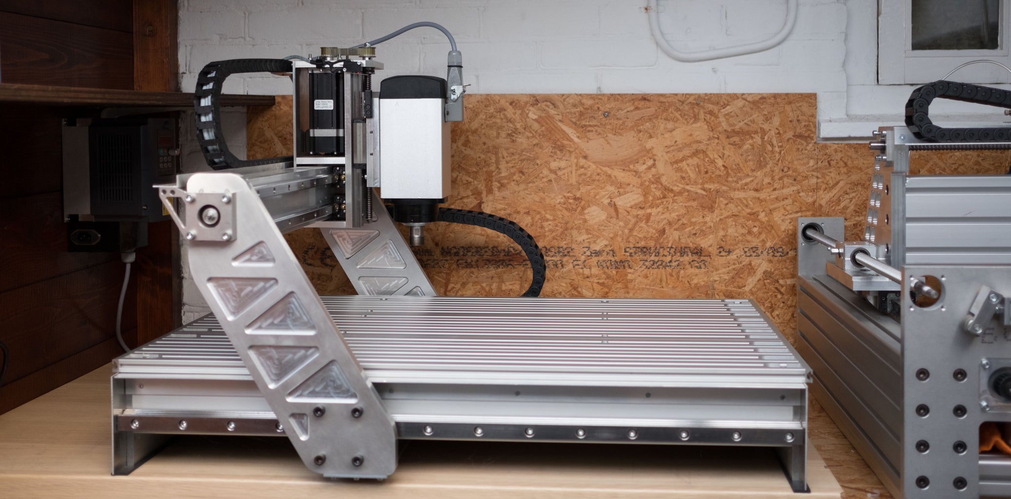
Step 2: The Frame


The frame provides the machine a rigid basis, not only to place it in your workshop but also for working on. To the frame the gantry will be mounted on sliding rails and later on a work surface. It also houses the stepper motor and spindle for the x-axis. I constructed my frame from 2 Maytec 40x80mm profiles, 2 endplates (both 10 mm thick aluminium), 4 corner pieces and a square structural piece.
All of the profiles are sawed right-angled and afterward milled exactly square. With the corner pieces a heavy (well relatively lightweight; it's all aluminium) frame was bolted together. The square frame made from the smaller profiles were mounted with 4 milled blocks (aluminium) on the inside of the Maytec profiles.
Since the frame sits beneath the worksurface dust could fall down on the guiderails (you want to keep them clean, more about that in step 5). To prevent this, dust covers were made and mounted around the guiderails. A angular profile mounted with brass milled t-nuts onto the may tech frame and 2mm aluminium plates mounted in the milled pockets on the endplates.
On both endplates bearing blocks are mounted for the spindle. They were hand milled and lathed to the right tolerances. On the front endplate mounting slots for the stepper motor were milled
Step 3: The Gantry


The gantry is the bridge between the x-axis guiderails and supports your milling motor above the workpiece. The higher you make it, the thicker the workpiece can be. There is however a disadvantage of high gantries. They work as levers on the guiderails and on the other hand the side plates tend to bend more easily by making them longer.
Most of the work I planned to do with the CNC involved milling aluminium parts. An average vise for the machine would be 60 mm high. Since the thickest blocks of aluminium easily available for me would be 60 mm high as well, I chose to space between the work surface and the piece of metal, which could hit the workpiece first, to be 125 mm. This gave me a starting point for the side plates. Since I wanted the center of an end mill hovering over the center of the runnigblocks (from the machines side view), the side plates had to be placed at an angle. Solidworks helped me to convert all of the measurements into the final parts. Because of all the complex dimensions I decided to mill these parts on an industrial CNC mill, this also gave me the opportunity to round all of the corners (would have been very hard to mill on a manual mill).
The part which supports the y-axis guiderails is formed out of an 5mm thick U-profile. It is mounted between the side plate with the help of two simple mounting blocks. On the inside the U-profile houses the y-axis spindle. Which is again supported by the same bearing blocks used for the x-axis. They are mounted on the outside of the side plates.
Beneath the main frame a plate was mounted on the underside of the gantry's side plates, giving a mounting point for the x-axis spindle nut.
Step 4: Last Movement


The last movement is what I call the Stepermotorhousing for the z-axis (plus the z-axis itself of course). It is constructed out of a frontplate mounted on the y-axis linear guiderails, 2 reinforcement plates, a motor mount and a backplate. On the front plate 2 linear guiderails were mounted for the z-axis onto which the Mountingplate for the milling motor was placed with the runner blocks.
The motor mount has the bearing for the z-axis spindle fitted into it. So I didn't use a bearing block for this spindle and is only supported on the top. he lower end is floating behind the mounting plate for the milling motor. The spindle nut for the Z-axis was directly bolted on the mounting plate for the milling motor.
The backplate provides a spot for the y-axis spindle nut to be mounted; it is mounted on the inside.
All of the custom mechanics are now ready. The CNC is assembled with the guiderails, spindles and a lot of bolts ;-)
Step 5: Guide Rails


Since your endmills need to move in 3 directions, the machine guides them with its guide rails. The guide rails provides the machine its rigidity in all directions except the one it moves in. You want them to let the machine only move in the preferred direction. Any backlash in other directions results in inaccuracies in your workpieces.
On my machine I wanted to use guideways supported on the full length of the rail, reducing the risk for deflections on the longer axes.
In my opinion some kitchen drawer slides are preferred above the hardened steel rods which are supported on the end (yes! they will deflect). Since you are constantly fighting the forces from the endmills against the material of the workpiece, a lot of support is recommended.
I chose the most expensive option; profiled linear guide rails with runner blocks. The are designed to receive forces in all directions. In the third picture you can see the looping bearing balls, they are positioned on both sides of the profile. All with a tangent 45 degree relative to each other, giving it the ability to handle high loads.
To get all guiderails perpendicular and parallel to each other they were all aligned with a dial indicator (with a maximum difference of 0,01 mm). If you spent your time on this part, the machine will perform very well in accuracy!
Step 6: Spindles and Pulleys


The spindles translate the rotational movement from the stepper motors into a linear movement. When building your machine, you can choose between three different version; leadscrews or ball screws, either in metric or Imperial configuration. The main difference between leadscrews and ball screws is the accuracy and friction. Leadscrews tend to have a lot more friction and are less precise than ball screws. If your looking for a very accurate machine without any backlash, you should definitely consider ball screws. However, they are relatively expensive!
I chose to use leadscrews with a special plastic drivenut which reduce friction and are approach a backlash free system. You can order the drive nuts here: http://www.mixware.de/index.html\
Both the ends of the x- and y-axis have to be turned to size to fit the bearings, pulleys and clamping nuts. Since the z-axis spindle is only supported on one and with a bearing, it is turned on only one side.
The pulleys are drilled to the turned shaft size (in my case 8 mm) and provided with a M4 setscrew perpendicular to the shafthole.
Step 7: Worksurface
The work surface is the place you will clamp your pieces of material on. On a lot of professional machine a T-slotted bed is used, giving you the option the use T-nuts and bolts to clamp your materials or vices. I chose to use a square piece of 18 mm birch-plywood on which a screw the materials and replace it when needed. An affordable work surface! You could also use Mdf with anchor nuts and bolts. Try to avoid screws and nails in Mdf, it doesn't grip them as good as a plywood board.
The work surface could be milled flat by the machine itself after you've completed it. Your first project :-)
Step 8: Electrical System


The main components in the electrical system are:
-Stepper motors
-Stepper drivers
-Powersupply (or 2)
-Breakoutboard
-Computer
-And last but not least: Safety first; a emergency stop ;-)
I chose to buy a complete set on Ebay with 3 Nema 23 stepper motors, 3 suitable drivers, a breakout board and a 36 V power supply. I use a step down converter to convert the 36 volt DC into 5 Volt DC. You can of course also put together your own set. Since I could not wait to sartup the machine I temporarily mounted all the drivers and power supply on a open board. The enclosure is in the making.
Since a few years it is also possible to connect a CNC very easily via USB. The UBS-breakout boards on the market generally come with their own software. I chose to use the parallel printer port found on most older PC's. I do not intend to use a new computer in a room full of dust, oil and aluminium chips
Since I had a lot of difficulties in finding a proper scheme with the needed components, I tried to make everything clear in the infographic above (you can also download the PDF and zoom in on the different parts)
Attachments

Step 9: The Milling Motor

Since we want to remove material from the piece we clamp to the work surface, we need something that drives the cutting bits; i.e. the endmills. The milling motor will spin the cutters at low or high speeds. From a simple Dremeltool to a High frequency Spindle of several kWatts. For our machine size a Kress spindle is very convenient to start with. If you want to improve your machine, a reliable Hf spindle will please you. It all depents on the amount of money you can afford to spent on it.
Try to find something with the ability to use different sized collets.
Step 10: CNC Software

In the topic CNC software I'll discuss not only the program me that controls the machine, but also the software which produces code the machine will understand.
When we make a workpiece on our computer, either flat or a 3D CAD (Computer Aided Design) model, we need to convert it into something the machine will understand. With CAM (Computer Aided Machining) we can read vectors and 3D models and create an output suitable (Gcode) for the software which controls the machine. I'm allowed to use the professional software offered by my University
The software that controls the machine is a Gcode interpreter. When you use a USB-hub, as discussed in Electrical system), it will have it's own software. If you use the parallel printer port on a older computer, you can choose your own. I chose to use Mach3 since it it used by most hobbyists. You can find a lot about it on forums and google. Since Mach3 has many options and functions, I won't explain them. Just play with it and you'll discover its secrets :-)
Step 11: It's Alive!!!


Ones connected properly, hookup the power supply, it just works!! Start with some pieces of wood or foam and you'll get used to the speeds and properties of your machine. The work above shows some of the pieces I'm working on in aluminium. As you can see the machine is able to work very intricately.
Search for proper parts and take your time. I could have build the machine in a month, but because I had to search for parts on Ebay etc., it took me half a year. This keeps the costs down of course, I was able to build the machine for less then €1000,-
I hope the story encourages you to build your own CNC milling machine. Please feel free to contact me or give a comment if you think something is missing.

Second Prize in the
Metal Contest

Second Prize in the
Gadget Hacking and Accessories Contest


