

Introduction: CNC Basics (Building a Cnc Machine Part 1)


So you want to know more about how to make a CNC machine?
Whether it is a 3D printer or a mil of some sort, this will take you through the basics a give you a nice idea of how they work, operate and what parts you will need or can choose from.
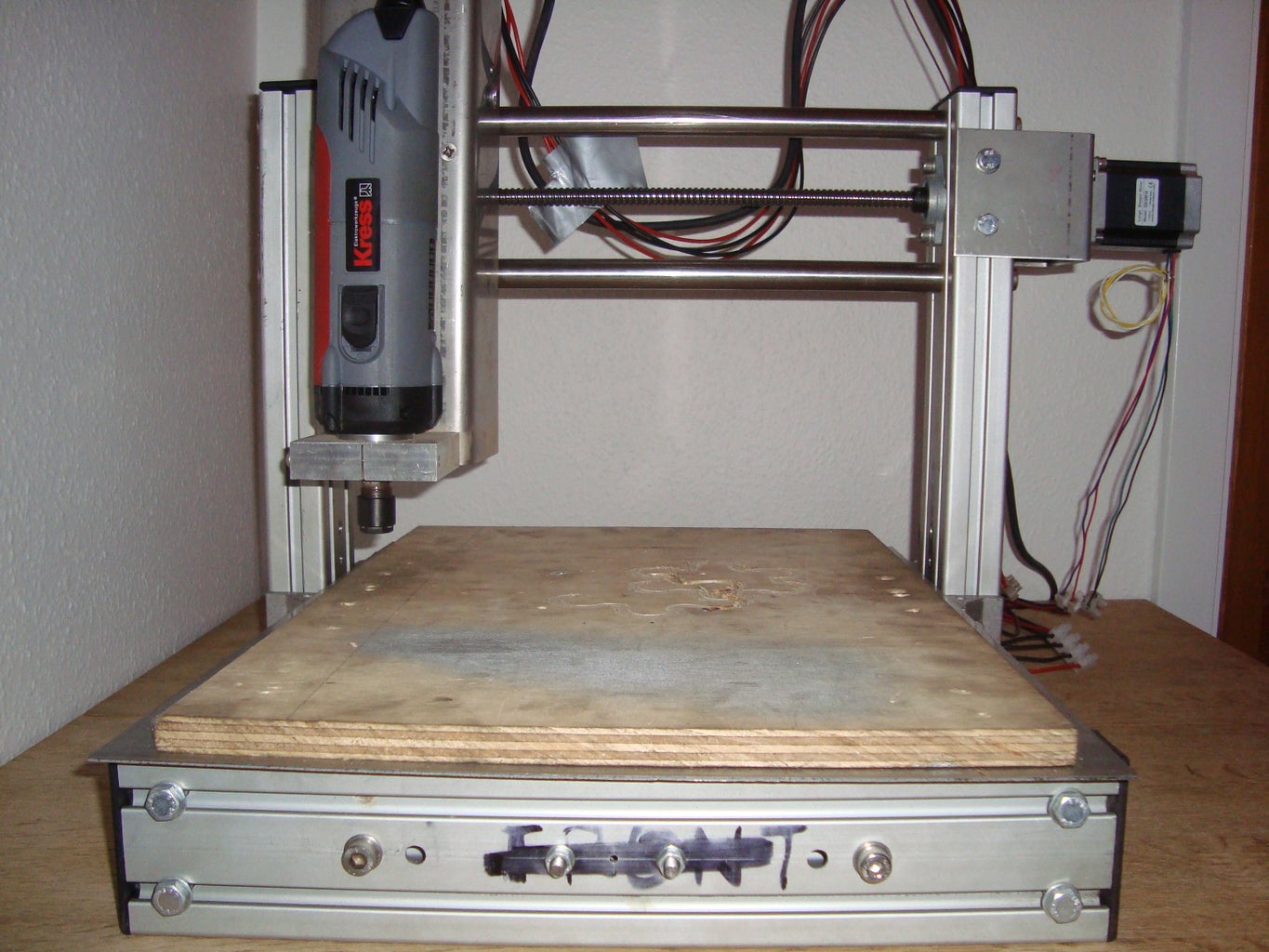
Fist of I have built my own CNC router with a pretty good result, and currently working on a combined printer, router and laser cutter.
What is this CNC stuff anyway? CNC stands for Computer Numerical(ly) Controlled in short, it works with your computer 1s and 0s to signal your motors to start and stop and stop, run and reverse when you want it. If you like to know more about that
I suggest you hit it up on the net, there are tons of nice explanations there.
and the next steps will take you through the different main parts of the machine, and what you need to know about them, to make the most of them, as understanding them will help you to a long lasting machine.
The basics of a CNC router, lathe or 3D printer is pretty much the same, the bigest differance is how they operate and is controlled, the router and lathe remove material from what they are working with to achive their goal, and the 3D printer adds it but the main parts will be the same no mater what system you want to build.
the guide will be made up of different parts, focusing on different aspects of the build. And guideing you all the way to make your own wonder! Also please comment my work (in any constructive way), and ask as many questions as you like! This way I can improve the guide as I work.
Thank you
Step 1: The Basics First

What does a CNC machine consist of?
For the main
electrical parts it will consist of
- Computer
- Breakout board
- Motors
- Power supply unit (PSU)
- Limit switches
In simple terms
The computer will run your program send the programs signal to the breakout board, the board will turn those signals into a new signal that will run the motors. The PSU is there to power your motors and or breakout board limit switches, and
all the other nice stuff you can mount on the machine. The limit switches are not a requirement, but they are nice to have, since your machine will then know when and where to stop, before it runs in to itself, which may damage the machine.
The main mechanical
parts are:
- Frame
Transmission
Bearings
Couplers
Guides (and their supports)
The frame of the machine is pretty obvious, it holds all the other components in place, and also gives the machine the stiffness it will need to work on objects, the transmission is to transfer movement of the motors to your axis, this will be covered a bit later.
the bearings keeps the spindles where it should be, and if you use the right bearing type, they will even help reduce strain on the spindles.
Couplers are the actual coupling between motor and spindle.
The guides are for guiding your linear movement and keep your machine steady while it works.
So now you should know what a basic CNC machine is made of, what happens when we put it all together?
Depending on the machine will most commonly have 3-4 axis to worry about, an X-, Y,- Z-, and C-axis
It works just like a coordinate system where you have X to the forward and backwards motion, Y to the left, and right motion, Z is for the ups and downs, and if you have the fourth axis it will control the rotations of your working object, as seen in the first picture.
This is pretty much the basics of the CNC machine itself, they may vary a bit from machine to machine, but all this will be cover a bit later.
Basic operation of the computer.
So how does the computer know where to go, and what signals does it send? This is a bit more complicated, but in short you will need a program that can interpret drawings and generate the code needed. There are different programs capable of doing this, but what you need to be looking for is something that can generate a G-code or an M-code, this is either done in your drawing program or a program known as a Computer Aided Manufacturing program (CAM) the code is then transferred to your control software, where it can be used to run from there.
Types of machines
There are generally two main types of CNC machines the ones where the work surface is moveable and one where the gantry is moveable
Recap
Alright that was the very basics of the CNC Machine. To sum it all up here are the main thing to remember
The computer runs the breakout board, and the board controls the motors, that are coupled to the spindles, where we have our guides, bearings and the stuff we would like to move.
Step 2: Considerations
Where to start
There are several ways to start your CNC project but before you start consider the following:
- How big should the machine be (work area X-,Y,C-axis)?
- Do i have a solid set of plans to build from?
- What materials do I want to be able to process?
- Do I have the necessary equipment/tools to make it?
- What materials should be used to build the machine?
- What type of motors (size) should be used?
- Transfer method (motor to spindles, gears, belts)?
- Moveable or fixed gantry?
- Make one from the scratch or fit motors to an existing machine?
- Fastening objects to the machine
Dimensioning
The dimensioning of your machine can be done in several ways, you can either decide on the max frame width, length or height, dimension from how big you want your effective work area or from the size of you spindles. Decide this early on and stick to those measurements. Remember depending on design your motors might be
sticking out of your frame. Also the frame needs to be able to absorb the vibrations when the motors are running, and changing direction.
Plans for planning
Planning your project will save you a lot of time, and money, either buy a good one, or spend some time in front of your drawingborad/computer. Having a good plan in your backpocket while building allows you to order the right ammout of parts the first time, and shows you where and when to do what.
Materials to work with
This choice will heavily affect the way your frame should be constructed, the “lighter” materials you choose, the lighter construction, material like soft wood, foam, aluminum is in the soft end, and materials in the heavy end is iron, steel, stainless steel, for those you will need a highly solid machine to achieve smooth results. Also if possible avoid using wood as a frame, I know it is cheap and easy, but it you want something that will continue to be precise, you will need a metal frame, as wood is a living working thing and this can bend, contract and expand.
The tools
This is where I see a lot of tutorials cheating, they go in to great detail about their work, and all of a sudden, “Oh I had a friend with a huge machine that could cut all of my parts” the better tools (high accuracy) you have the better results you will get! Not that it can not be done by hand, but the results may vary, and you’ll end up with some parts you have to redo to get things straight and even. So consider if you have the tools, or you if you have to buy finished parts, how much that will cost you. The right tools and the right materials will get you a long way though.
Motor size
Again this will depend on the materials you want to work with, stepper and servos com in all shapes and sizes, and the amount of torque the they deliver should be enough to pull or push the load your adding to them.
Transfer system
This is where you have to pay attention use the right system the right places, threaded rods are not spindles, they are for bolting and holding things together! And you will see a lot of people using them because they are cheap and easy to get. But they will not last very long as they were never intend for that use, either use belts (avoid belt driven Z-axes though), trapezoidal thread or ball screws, each will have their own strengths and weaknesses, which will be cover later.
Moveable or fixed gantry
This is a matter of taste, really, the fixed gantry is simpler to build and the most commonly used type of CNC machine, this often allows for a more sturdy build and stronger gantry support as well as better support from the bottom up. The moveable gantry takes less space when it is running, but is a bit more difficult to build and run stable and it is a bit less supported.
To make a CNC machine from scratch or modify and existing one
If you know where there is an old router, or bench, or you already have one, no matter the size, it is quite simple to make it in to a CNC machine, think about it, all the stuff is already there, it just needs some motors to run the axes and you are good to hook up the rest.
End of the where to start
You now have something to think about, it is important you make your mind here, and stick to a plan, redesigning in the middle of the project can be very expensive and time costly. It is however important that you find your overall measurements, either by defining your work area, the max frame size you are able to house or place in your house, the kind of materials you want it to work with, this will help you a lot when it comes to the dimensioning of other parts.
By now you should have some idea of what you need and why you need it, it is time to take a deeper look at what you can get. In the next step we will have a look the mechanical parts.
Step 3: The Mechanical Parts


This is where price and precision really comes together, a fully stable and supported, long lasting machine will in no way come cheap! This is why industrial machines are so darn expensive. So this is where your considerations come in what do you need? While a 3D printer only needs to be stable, safely mounted, a router will need to be much more solid since it will be ramming a high speed tool down on and in some sort of material. As a good rule of thumb you will need stronger/thicker materials than the material you are going to work with. Try to use your materials the way they were intended.
The frame
The frame is as mentioned earlier the frame is what will support the whole thing, and this is where your designing-skills comes into work, there are no right and wrong way to design this part, as long as you keep the forces that will affect the frame in mind, some will say you have to make the gantry a special design to get the best result, and yes, if you want to make it as slim as possible this is true, however if you do not have the ability to calculate a load of forces affecting your machine, there is another trick, over dimensioning or reinforcing, this might not always be pretty, but the first 3D printers or CNC routers or mils was no pretty sight either. You will most likely have to optimize your design as you work or get things finished. To avoid setbacks here try to keep things simple. I know there are a lot of pretty pictures out there showing off different cool frames, but they most likely had the more advanced parts made by another machine, and that will be costly, unless you have that good-friend-to-pull-out-of-your-hat-trick.
However I will always recommend not using wood or plastic to build the basic frame from, yes it is cheap and easy to work with, but it will not give you a stable machine in the long run! As I mentioned earlier, wood is a living thing, and any woodworker will tell you this, and when it comes to precision this is bad! One day you might get really nice results, and the next you will have a bumpy ride. This is not only on the product you are working on, it will also affect you mechanical parts increasing the strain on them.
Also it is important to decide your type of bed here, should it be moveable and the gantry fixed (I will recommend that, due to a simpler first build) or should it be with a fixed bed and moveable gantry, as this will affect your overall design.
The guides
Alright you have a basic frame to work with some sketches will do now it is time, so now it is time to decide on what guides to use. The guides are quite important, and even more the limits of your guides. So lets have a look on the different type of guides you can use. Since there are a lot of different ones, and mainly there are 4 main types of guides, rods, rails, supported rods and the DIY-way-to-go
Precision rods
Rods are commonly used, since they are cheap and easy to use. But they have one huge disadvantage, they bend easily, a normal recommendation is you should only use rods for machines less than 500mm in length, otherwise they will get too soft and flex too much when they are under pressure. I did test this myself on a
prototype, and even when I used rods twice the size I still encountered the same problem. An even bigger problem with rods are, there are no way to reinforce them but adding size. Also I looked over some papers doing the higher end math on rods, showing that even without any weight to pull them down, their own weight is enough to the trick, even though it is only by fractions of millimeters.
Also you should avoid normal iron, pipes, plastic pipes and so on. Use stainless steel or even better real precision rods that are stainless and hardened to an extend that ball bearings will not wear them down over time.
If rods are the right thing for you, here is how to mount them:
- Mounting support.
- Make inside threads on the ends of the rods and make a smaller hole through your frame, and use a bolt to fasten it.
- Drill a hole halfway through your frame and make sure it fits 100% in both ends (not recommended but used on some designs)
Depending
on your design you will need around 6 rods, 2 rods in the X-, Y-, and Z-axis, and about 12 bearings.
Rails
Rails are in the expensive part of the guides, but they are well worth it, depending on the rail type, you can support these as much as you want to, due to the fact that they are mounted on flats surfaces. The down side to rails are that they are very sensitive to dirt so they do need a bit more protection than rods would. I did some research on the rails and it seems that there is no big difference in manufacturing price when it comes to the smaller ones to the bigger ones. The smaller ones around 15mm in size will take about 10-20 tons of
pressure before they start failing, and the larger ones will take a lot more. And the price difference is the extra materials used. So if you are going with this solution the small ones will do the trick.
Rails are relatively easy to mount, and if you buy them the right place you will even get a nice instruction on how to mount the first one, and then using the first one how to mount the other one.
Again depending on your design you will need about 4-6 rails. The best would bed to put 2 rails on each axis, but there are other designs using only one rail on the Y and Z axis.
Supported rods (also called rails)
"Wait! you just said you could not do this!" and yes, but some engineer decided that this should be possible anyway, but they are more a combination of a rod and rail, than anything else. This is basically achieved by cutting a wedge out of the normal bearings, and by that giving room for a support to hold the rod. This is
cheaper than rail but still a bit more expensive than rods. And they are mounted the same way as rails are.
Again depending on design you will need 6 of these. 2 for each axis.
The DIY-guide
A common DIY guide is 4 ball bearings on a 90 degrees angle profile. This is easily made, cheap and pretty strong, but mounting it can be a bit more difficult, there are tons of ways to do it, but they are all inaccurate in some way, welding, sticking them on, drilling holes. Good results can be archived if you know what you are doing, and have the time, patience and tools to get it just right.
Transfer method
So now we have the guides, in place let have a look at the mechanical heart of the machine the transfer method. In this category we have 3 main types of getting movement to our machine, either we are using spindles, belts or gears.
Spindles
There are 3 kind of “spindles” I would like to cover here and one of them is not a spindle at all, but many DIY people use them for some reason, I can’t figure out if they use it because it is cheap or just because they don’t really know of their alternatives, in any case it pains me to see peopel work so hard for a cool result only to make a shortcut that will eventually force them to remake some of their parts.
First of the wrong way to do it, is by using a simple threaded rod and bolt, they are easy to get, cheap and it will be the death of your hard work since you will be changing these as often as you would change a cheap second hand lightbulb with water in it. They simply was not made for that kind of use and the threads will tear very fast, and increase backlash as they do it. Treaded rods and bolts are for bolting your things together and making sure they stay where you want them, and they are good at it, so use them as intended. If you must use a threaded rod, at the very least use a copper bolt.
A real spindle is like a threaded rod, but the threads are much thinker and durable, and there are two main kinds of them, the cheap trapezspindel, and still one of the most widely used spindles in the world, the down side to it however is its backlash, some programs can compensate for it but a better way to deal with it is an anti-backlash system to eliminate it all togeater. The most popular trapezspindle is often made out of copper, as copper is considered self-lubricating.
The other kind is a ball screw, and again this is in the expensive range of the industrial world, but they are worth it on bigger machines, due to the fact that a high end ball screw will have no backlash mentionable to even high performance machines. The drawback however is they are very sensitive to dirt.
No matter what type of spindle you choose, remember to support it in both ends with bearings designed to the job, I know there are some DIY bearings out there, but make sure that the bearing is “flexible” enough to give a bit from the strain it might get, this will ultimately save your spindle form long term damage.
Belts
It is also possible to use belts to drive something forward this is also a cheap and easy way to move your axis, but it has some limitations to it, first of all it is rubber, it wears, and good belts does not come cheap the cheaper ones will slack slowly or break if the tension gets too high. Also I would never recommend using a belt for de Z-axis, I have seen some systems use it, but the weight of the axis will put it under a lot of strain, also the axis will need to be forced down in to the material you are working with, and held steadily there for a period, and the belt drive can have some problems with that. So if you can use a spindle here!
Gears
Gears are not found round, they can also be long and flat sort of, though I have no experience with this type of transfer, I have seen some people use it, my guess though is it might only work really well in certain situations and it might not be suite to the Z-axis.
Step 4: The Electrical Parts


The electrical parts are the main nerve and brain of the machine; it will not only run your system but also give you a lot of features and safety.
Remember and I can not say this enough, never work with your electrical parts while they are on or operating! Always turn them off and remove their powersupply!
The computer
The brain of the machine, or at least the one commanding everything while you watch! If you want to make all your drawings and codes on the same computer, then I suggest you get a decent computer, that is able to run the load of the programs, if you only want it to run your machine, with the command program, then an old computer will suffice, a lot of breakout boards still use parallel cables (the old printer cables), so either make sure your computer is compatible with them, as USB solutions can be expensive, if your breakout is not does not support it
from the manufacturer, and sadly a normal converter (from USB to parallel) will not do the trick since the protocols are different.
Personally I have an old computer standing just to run my router, It is cheap and I do not need to care so much about it.
Breakout board
The breakout board is the machines nerve system, it sends and interprets all the signals, form motors to Emergency stops (although you should always wire an E-stop to cut all power to your system), to limit switches While there are many breakout boards out there, or you can make one yourself, I suggest you do some research on the board before buying it, some models are closed and almost secretive source, and can be difficult to figure out if anything goes wrong. So do ask about support for the board. Mainly there are 2 types of breakout boards,
the “controller” board and the “all integrated” board.
The controller board only controls signals and relies on another drive to, runs the actual motor. This takes up a bit more space, and I’m not really sure if there’s any big advantage to gain with this method over the other.
The all integrated board, only needs a power supply and then it will take care of everything, from running the motors to monitoring signals. It takes up less space and is a bit cheaper compared to the fact you do not need drives to run your motors. Again I do not see any big advantage over the other. So just choose what suits you the best and what you can get the best support for.
Power supply
The power supply unit (PSU) is important, and you will need to determine if you need one or more of them to run you complete system. Be absolutely sure to get the right one here as a PSU with to low voltage can not start your system, and one with too high voltage will fry your chipset, motors almost instantly! The power supply must fit your system, and most distributers will be able to tell you what to get depending on what you have. Again remember never work with any of your electrical parts when they are turned on, power them off and remove the
power source completely before working with anything electrical, this means
unplugging this unit when it is hooked up! Also remember that PSUs do get hot while they are working, so when you place them, it is best to place them somewhere with a bit of space around them, and with a bit of cooling.
Motors
There are two main types of motors used for CNC machines, this is stepper motors and servo motors, while their build and the way of controlling them is completely different, and I could go on for ages about their principles, lets suffice to say that servos are of a mechanical build up, with gears and are controlled with pulse
length. Stepper motors are more of a little brother to the electrical motor, it uses a magnetical field to turn and hold the position and is controlled by changing the filed inside of the motor. If you want to know more, I suggest searching for how dos a servo-/steppermotor work. Just remember the bigger motors you get the heavier load you can push/pull, always strive to get the smallest amount of weight/resistance on your axis, this way you preserve power for where you need it.
Limit switches
Limit switches comes in all shapes and sizes, but they all do the same thing, they turn on and off when something comes near or touches them. They will sometimes need their own power supply (this is mostly common with the proximity sensors) to send a signal. A nice word of advice is to set up your switch to send a signal when it is not active, and not to send a signal when it is active. This is called negating a signal, and can be done in most of the programs you use to run your machine. Here is the reason. If you set your switches to be active when they are touched, they will only send a signal when the machine is at the end of its working area. The problem is, if there is some sort of fault in the switch or one of your wires has broken, cut or fallen off, the switch will not
send a signal indicating that the machine is at the end of the line, and it will run straight in to your frame with a high risk of damaging something! This can be avoided by doing the reverse thing, setting the switch to not send a
signal when it is activated, in this case if there is a faulty connection somewhere, you will get the warning as soon as you start your system. This is common practice on almost any safety system out there.
Bundle up
The most common thing is probably to buy a bundle where you get your motors, PSU, drivers if needed and breakout board, this way if you are not completely sure about how things fit together you are sure to that the bundle will match your needs.
Extras
There is all sort of extra stuff to add to your machine, depending on what you would like to have or see, one of the most common things to add is a display with the computers DRO (digital read output) this screen tells you where your machine is in X, Y, Z, C coordinates. There is also display showing the amount of voltage
or amps your system is using, this can be used to see how stressed your system is, the more stress the more juice is needed to run. This also inclueds buttons for manuel control,

Participated in the
Full Spectrum Laser Contest


