

Introduction: Catch the Red LED!


This Instructable will show you how to make a simple, fun game using a few breadboard components and an Arduino. Have fun!
Step 1: Tools


For this project, you will need a few simple tools.
-Wire strippers
-USB to USB-B cable (or whatever fits into your Arduino board)
-Computer with the Arduino software installed
Both the wire strippers and the Arduino Uno can be bought easily off Amazon, and you can download the software for free on Arduino's website.
Step 2: Materials


You will also need:
-Arduino (we used an Arduino Uno)
-Breadboard (half size or full, doesn't matter)
-5 or more LED's (we used 5- 2 green, 2 yellow and 1 red)
-330 ohm resistor
-10K ohm resistor
-Wire (or jumper wires)
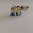
-Momentary pushbutton
All of these materials can be found on Amazon or at your local RadioShack.
Step 3: Breadboard Layout

This is what your finished breadboard, with all components installed, should look like. You can build your circuit based on this, but we'll also go into more detail in the next few steps.
Step 4: Construction- the LED's

You may be saddened at the thought of having five different 330 ohm resistors, one for each LED. Thankfully, you don't have to do this! Connect each of the LEDs' negative pins to GND on the breadboard and wire a resistor from GND on the breadboard to one of the pins labeled GND on the Arduino (this is shown with the GREEN wires). However, in order to control the LED's separately, you can't just connect them all to the positive rail. Instead, wire each positive pin to a separate pin on the Arduino (shown with the RED wires). To use our code, connect the LEDs as shown to pins 9-13, with pin 11 having the red LED.
Step 5: Construction- the Button

To hook up the button to the circuit, you'll need to use what is known as a pull-down resistor. This resistor ensures that the LOW voltage from the button is really 0 instead of giving some erroneous value that causes a "false positive". Connect one side of the button to the 10k resistor and and the 5V pin on the Arduino, and the other side to pin 2 as shown in the picture.
Step 6: The Code


This is all of the code that will be used to control the game. We'll go into more depth about each of the sections of the code next!
The full code:
void setup() {
// put your setup code here, to run once:
Serial.begin(9600);
pinMode(3, INPUT);
for (int led=9; led<=13; led++){
pinMode(led, OUTPUT);
}
Serial.println("Welcome to Catch the LED!");
Serial.println("Your goal is to catch the red LED");
}
void loop() {
// put your main code here, to run repeatedly:
for (int led=9; led<=13; led++){
digitalWrite(led, HIGH);
if(digitalRead(3)==HIGH && led==11){
digitalWrite(led, HIGH);
Serial.println("You caught the red LED!");
}
else{
Serial.println("Sorry, you lose!");
delay(150);
digitalWrite(led, LOW);
}
}
Step 7: The Code- Void Setup
This is the section of the code that only runs once to "initialize" the program.
-You'll notice a "for" loop in the code. This particular for loop will "count" from 9 to 13, then makes the corresponding pins on the Arduino outputs. We also have a separate line to list pin 2 (the button) as an input.
-The instructions are listed in this section (using Serial.println because this separates the lines of text) because if they were in the void loop section of the code, they would print infinitely, and we don't want that.
Step 8: The Code: for Loop
This section of the code will repeatedly light up the LED's in sequence over and over again.
-This uses a similar for loop as the previous section, but this time instead of making the LED pins outputs it will light them up.
-The delay() function, in this case set to 150 or .15 second, can be adjusted to make the LEDs flash faster or slower.
-If you have more LED's, you'll have to change the numbers (in this case 9 to 13) to suit your pin numbers.
Step 9: The Code: Button Triggering

This section of the code determines if you've won the game or not
-If the button is on, it will also check to see if the red LED, pin 11, is HIGH or on.
-The code will also print to the serial monitor the results of the button press (whether you won or lost), and you can adjust the message by changing what is in the quotes of the serial.println functions.
Step 10: The Finished Project

Once you're done, your Catch the Red LED game should look something like this! Just upload the code and you're set to play. The rules are simple: Press the button when the red LED is lit and you win. Otherwise, try again.
Happy building, coding and playing!
Step 11: Future Modifications

If you're interested in expanding this project, there's a few ways I could think of making this game more of a challenge or more fun.
-Add more LEDs, in as many colors as you like!
-Less delay in between the LED flashes to make it harder
-Have two LED's on at once and try to catch both of them at the same time
-Make a cool enclosure, by 3D printing or otherwise
-Get one of these super-cool buttons off Amazon!


