

Introduction: Complete Newbie Step by Step, 3D Printer With All Parts Lists


Intro, prelude, or just: who is this meant for?
I wanted the title to include cheap, but lets face it: it is not cheap to build a 3D printer unless you have some/most of the components on hand or if you find just shy of £100 as cheap to make a tiny, not very good quality printer. This tutorial is all about starting from zero, figuring out and understanding all parts of a 3D printer and keeping costs down for this our very first build.
The upside is that all the items can be reused for a larger better printer at a later stage. I did that, and it Works wonderfully - better than an Ultimaker original in fact (proud).
It should be obvious which one is made from old CD/DVD drives, and which one I reused my parts in later :) I opted for a small printer, but you can just ordre longer metal rods and get a larger cabinet, and you have a larger printer at the same cost.
I have not kept strict tabs on costs, but the final printer, which is awesome, amounted to a total of just over £200 or so.
In short, I'm going to build a 3D printer made from parts from old CD/DVD drives and some aluminium pieces. I am going to provide complete detailed description on every single part needed. There will be norequirments on having advanced or expensive tools nor expert knowledge on anything.
This project is about learning how the individual parts of a 3D printer fits together, to learn the basics here and move to larger projects later where we can reuse all the parts worth more than £10. I did exactly that, and made myself a larger fully functional printer.
There are many, many other instructables around, and some of them have inspired me to make my own instructable. Read on, and you will see why I felt compelled to make this instructable.
I've been looking at making both CNC machines, a 3D printer and even a combined CNC and 3D printer for a while. Mostly looked at either very, very cheap ones (still more than 3-5 times the cost of this one) that could either do CNC or 3D or the very expensive kits. Mostly just drooled on the kits to be honest, as I wasn't going to spend over a thousand Euros on this. Especially not untill I know for sure I would get a good endresult. And I surely didn't know that at the start of this project.
Most recently, I have been looking a lot at Combination CNC Machine and 3D Printer (here on instructables) that is placed somewhere in my max end of costs and in the very high end of quality. While the writer is keeping expenses down it still run up in some hundreds Euros... and that was without having local prices. I was apprehensive about commiting to this, as I wasn't sure I could ever finish it, and some hundreds Euros is just a lot to spend on uncertainty.
Common for all the articles, tutorials, youtube etc. though, was incomplete listings. At least incomplete for my level of DIY competence as I couldn't figure out missing steps on my own without risking spending triple the cost of that particular part as I might buy something a few times before I got it right. This is the gap I hope to cross with this instructable. There is no hidden need to lasercut, pre 3D print, CNC mill, use big stationary machines, non-normal household machines or anything like that in here.
Most advanced "Machinery" used in this instructable is a soldering iron or maybe a multimeter - depending on your mileage.
Why was I unsure about wheter I could finish any of the other DIYs I looked at?
- Lots of the parts listed has to be fabricated!
- Lots of the parts listed isn't readily available where I live.
- Lots of parts are not clearly described in instructables, so I am unsure what to buy or how to assemble my stuff.
- Import taxes are very high in Denmark, so buying outside of EU is not often a good idea. (English is not my main language either).
- I can solder, I made an Arduino Uno once, but I am in not comfortable soldering Electronics..
- I can't come up with Circuits on top of my head, which seems necessary for many Projects.
- Most projects seems to imply that you really know your way around Electronics, which I do not do.
- Powersupply requirments are mostly rather fussy and it is taken for granted that you know how to construct this yourself of old parts or compeltely wire from new parts on your own. Without documentations.
- The entire wiring part is most often missing entirely so I'm left wondering.
- I own a Dremel + some accessories for it, but I am in no way a precision metal- or woodworker.
- I do not have a drill-stand, nor a band-saw or any other stationary powertools with names I don't really know.
Lots of explanations and steps are missing in every single article I have read. It might be due to me being a novice, but it means I can't use them. Most 3D printer instructables come across as "see what I can do" instead of really instructing me in anything.
I do not have a working-shed filled with all kinds of stuff to use in DIY Projects like these. For me, it translates into having to buy everything to get started and struggling to find fitting parts if nothing is listed.
So, I just think I'm better than everyone else at writing a 3D printer instructable? NO! I just target a different audience. The audience I am a part of. - at least at the start of this instructable :)
Why now, and where exactly in regards to know-how?
- I have read a lot about how a 3D printer Works, but there is a point where reading just stops being usefull to me and hands on is the only way forward. I believe I am at that point now. I am a learning by doing kind of person.
- Instead of contructing a large fullblow CNC/3D printer machine, I decided on making a smaller model to figure out the ins and outs before embarging on much larger scaled machines.
Does the above lists describe you? Then I hope we find the answers in my instructable.
Step 1: Table of Contents
- Intro
Intro, prelude, or just: who is this meant for?
Why was I unsure about wheter I could finish any of the other DIYs I looked at?
Why now, and where exactly in regards to know-how?
- Table of contents
- Parts needed / shopping lists
- Tools you are going to need
- Items specific for this project you might have or can find for free or cheaply
- Basic items and materials needed
- 3D printer specific parts list
- Price total
- Decomissioning and converting our dvd drives
- Parts we want to salvage from our CD/DVD drives
- Why do I want to use 3 C/DVD drives
- Cutting off protrusions and drilling mountholes
- Stepper motors: soldering wires and figuring out pin out
- Finding coil pairs
- Soldering
- Testing for short Circuits
- Creating 3D printer framework from dvd chassic and parts.
- Creating a mounting bed and mounting the "Y" stepper/frame
- Powersupply
- Preparing our PSU
- Word of warning.
- Looking at PSU innards 12V leads.
- Making 12V connections for our Ramps board
- Preparing and connecting our wires.
- 12V 11 Amp cable
- 12V 5A cable.
- Sorting out the wires.
- Preparing our PSU
- Arduinog Mega 2560 R3 Setup
- Software - Arduino Environment (Arduino IDE)
- Connecting and testing the Mega 2560 to the Computer.
- Initial setup of Mega 2560
- Verify Mega 2560 functionality with a bit of example code
- Ramps 1.4 Control Board + 4X A4988 Stepstick Driver Modules - description
- Description
- Features of driver boards.
- Before usage / Preparing for usage
- Wiring up
- Power input
- Power output
- Stepper motors
- Important!!
- Temperature probe
- Endstops - Home positon.
- Endstops - When the home posistion has been achieved.
- You do not have to use endstops.
- Assemble and setup Arduino Mega 2560 R3 and Ramps 1.4
- Assemble Mega 2560 R3 and Ramps 1.4
- Warnings
- Download software
- Get the Marlin firmware
- Setup the Marlin Firmware in the Arduino IDE
- Defining Motherboard as RAMPS 1.4 with accessories
- Defining Baud rate, Extruders and Power Supply
- Defining Thermal Settings
- Temperature sensors
- Heater settings
- Minimal temperature
- Maximal temperatur
- Preheat Constants
- Extruder settings
- Defining End-Stops
- Axis movement directions
- Invert the stepper direction
- Sets direction of endstops
- Printer printing area
- Travel limits after homing
- Movement Settings
- Upload the firmware to the printer
- Verify stepper motor works
- Tesing and Usage
- Cura
- Pronterface
Extruder, Hotend, Direct, Geared and bowden etc
Have fun with this
That last step with the missing info and videos!
Iterations of the DVD-printer, strain-challenges and floppy-drive as Z-axis
Hotend - cold-end cooling.
Bowden tube - fixing it in place
Instructable on the new 3D printer?
No data feedback to the electronics
Future updates.
Step 2: Parts Needed / Shopping Lists


This is the items, parts and tools lists page. I'll try to be as detailed as possible.
If you order items from somewhere, see if you can order several items from the same place. At least if you have to pay for shipping, as shipping can very easily exceed the actual cost of the individual item.
Please let me know if you find anything unclear or find that I missed something.
I bought most of my items on eBay. Some in china, some in Europe.
After I had bought everything I experienced some malfunctioning hardware and then found http://www.miniinthebox.com/ which can deliver pretty much everything we need. It looks as if it is located in the EU but it is not in the EU. The items are shipped from Asia, so you want to pay a (very small) fee to insura against extra toll/vat on the items when imported.
Tools you are going to need:
- Multimeter
I bought a Multimeter XL830L on eBay. You can get it from HongKong for £5. You might find it cheaper locally, so look around.
You need this to find the right pin-out on the stepper motor, and to check for shorts.
Complete beginners guide on multimeters. - Some sort of small multi-tool to cut bolts and remove protrusion off of the CD/DVD beds is needed. Also used to cut the threadded rod into fitting lengths.
You can use a normal grinder I suppose (I don't own one) - Soldering Iron. Don't worry if you don't have one, you can get them very cheaply on eBay. Thera are also lots of guides on how to solder. If you do not know how to solder, this will get you started:
How to Use a Soldering Iron: A Beginner’s Guide
Either search for Soldering iron kits, or buy the parts individually:
* Soldering iron kit including all of the below from £12 (Try looking locally in a physical discount shop as you might find it way, way cheaper)
* Soldering iron £3-4.
* Soldering tin £1-2. (see if you can find one with silver. At least find one without lead (lead-free))
* A de-soldering sucker £2-3.
* Helping hand/3rd hand £3-10 - you need one of these to hold the wires and stepper motors while you handle the soldering iron and tin.
All said, if you plan on doing some soldering in the future, I can recommend getting a proper adjustable soldering station. It doesn't have to ruin you. I personally bought a Weller WHS40D last year at around £33 including shipping on eBay. You can find plenty of new way cheaper adjustable stations as well. - You need a set of small screwdrivers - all my CD/DVD drives was easy to take apart using standard small philips screwdriver kit containing sizes (stars +) PH00 / PH0 / PH1 - I had one drive where I had to find small torx M5, but I only saw it in one drive. Should be able to find a small set for £5-10.. or less.
- Normal machine drill. Nothing fancy. (hand Tool, not a stand or anything)
- A set of metal drills. See if you can find a set containing 10 or more ranging from 1-8mm.
- A set of Allen/Unbrako keys. I had to use the sizes 1,5mm, 2mm and 2,5mm for the Filament Extruder feeder kit hat attaches to the Nema 17 motor. I'd recommend getting a set with more keys included with some sort of holder/box.
- Hack saw. You (might) need this to cut the aluminium pieces we use. If you have a jigsaw, or can borrow one, it will be easier. You can do this using your mini-Tool, but it does take a while, and it really stinks up the place when cutting into Aluminum.
Items specific for this project you might have or can find for free or cheaply:
- 3x stepper motors from old CD/DVD drives.
Stepper motors have 4 wires and we want those. Some drives has DC motors with only 2 wires. We can't use them.
No way to tell from the outside unfortunately for sure, but I learned that if you can open the drive using a small clip, it might be a stepper motor. Can't open most DC drives that way (at least the ones I tried).
If we go by motors from CD/DVD drives only we have to make a counterweight on the Z axis. If you can find a floppy drive to salvage you can do without counterweight.
The Z height will be down to about 2cm with a floppy drive motor though! Need a stepper motor here also.
I actually just tossed some DVD drives a few weeks back, so had to buy mine (typical). I found 6 of them at £5 or so. Unless you can salvage endstops from the CD/DVD drives you (might) need to buy some of those.
Good read on how an endstop/limit switch works from RepRap: Endstop
I learned that many floppy drives have both optical and physical endstops that are compatible for our use.
I later found a nice package with 6 endstops you might want to Invest in, in order to reuse them for future 3D printer: 6pcs Mech Endstop Switch fo CNC 3D Printer RepRap Makerbot Prusa Mendel RAMPS1.4 at £6 with free shipping - item: 351156547800. This is going to raise your total price some though.
I did not use Endstops in my small printer, and I infact ended up using the much smaller, simpler and cheaper standard limit switches. These comes in different forms. With and without rollers, large or small levers etc. I ended up liking ones with small/medium straight levers and no rollers or other fluff.
Import thing is, that you do not need any additional Electronics or parts other than the limit switches themselves. The Arduino Mega has, what is called, Pull-up resistors on it, so we do not need to solder in any resistors or such.A normal powersupply from a computer. The standard ATX powersupply can give us the 5v, and 12v we need. These can be bought very cheaply as well. Can also easily get 7v from it if needed at some point.
You might have a 12v 8-15+ amperage black-brick powersupply somewhere. I had two of those, I once used for my Computer (picoPSU).A small fan around 30-40mm x 30-40mm to cool extruder head. Any old fan will do as long as you can attach it to blow at the extruder head.
Basic items and materials needed:
You might need to buy these items, but I have tried using components you can find usefull for years.
I recommend buying boxes of 100 or more of each. Not that you are using that many for this project, but it is a good way to starting up your DIY Collection. M4 denotes a diameter of 4mm. So if a nut is M4 it fits with 4mm bolts, which incidentially is named M4 as well. You can do this entire instructable with just the M4 size. Having some M3 is nice though, but I am really only going to use it for the heatbed level adjustments.
- M4 threadded rod. 1Meter.
- A box of M4 bolts/screws 30-40mm long. If you want to keep costs father Down, you can buy an additional M4 threadded rod, but it is going to take much longer with all the cutting out pieces to fit.
- M4 washers, lock-washers and nuts. Recommends 100 pieces box of each.
- Aluminum angle 25mm on each side, 3mm thick, 1meter long.
- Aluminum flat 15mm wide, 3mm thick, 1meter long. ( you can do without this if you want to).
- Aluminum flat 40mm wide, 3mm thick, 1 meter long.
- I found a piece of 8cm long 6cm wide 3mm thick aluminum I ended up using as heatbed.
I had originalle planned to use some of the 40mm wide aluminum and then attach a larger plate on top from DVD-casing.
When I build my Real printer later on, I learned that the material called ABS prints superbly on just Cold Acrylic plate! That Means you do not have to make a heated bed or make fans to cool the printed objects or anything, as ABS does not like fans. ( still neeed a fan to cool your Cold end, of your hotend (top part of it)). - Some wire. for the counterweight.
- Some plastic or metal tubing to fit around the threadding four our counterweights. I bought a 1m metal-tube that fit over the 4m threadded rod.
Maybe you can find some old small Wheels or something instead. - Some heatshrink to put around/over over wirejoints - you can use some other mechanical joints instead if that is more to your liking. See if you can find a box of heatshrink with different sizes. You want small sizes for this project. They are listed as 2:1, 3:1 or 4:1. It is how much they shrink when heated. Ie. a 4mm 2:1 is going down to 2mm diameter. A 4mm 4:1 shrinks down to 1mm diameter.
The more they can shrink the more expensive (normally). 4:1 is the normal range.
When you connect two wires you would want to solder them together in many cases. We put heatshrink around it to avoid shorts. - If you do not want to solder and use heatshrink to join up wires, you could take a look at the mechanical Wago connectors (prodcut info)- cheaper from german eBay. Going to raise your Costa lot though. I have some of these and I can recommend these. Especially as they are small and reuseable.
- Some thin wire. Salvage some from PC fans or similar. Less than 0,5mm diameter is needed for our motors. I do not have a digital measurement tool to read out the exact size.
- Some thicker wire. 0,5mm or 0,75mm. Get a lot of it. You can use thicker wires if you want.
Dupont male to Female Line Connector Wire Cable. I bought them at £0.99 pr 40 cables. I bought more later for my real printer, as they are awesome!
Dupont Male to Male Line Connector Wire Cable. I bought them at £0.99 pr 40 cables.
Don't go buy seperate Dupont plugs as you are going to pay a huge overprize compared to getting some sets as in #12 and #13. We are using the plugs from #12 and #13 to wire up everything to our RepRap board. If you buy individual plugs you also need to buy pins and a crimping tool.
If the Whole Dupont wires + connectors is too much of a bother to you, you can actually buy a complete cable set with everything you need (supposedly) for your Ramps 1.4.
Prices are not included in my totals. £12.95 + £1.15 shipping. Much cheaper than buying individual plugs but still way more than the Dupont approach.I had some rubber edge-liner I used on bottom edges to function as feet. You can do without or come up with someting else. Don't really need it unless your printer ends up with Sharp edges.
4x springs for Heatbed See if you can dig some up locally somehow. We are going to use springs to make sure we can level off our heatbed. Any springs can be used as long as you can fit them between the two plates we are using to build our heatbed.. See if you can find some with inner diameter of 3,3-3,5 to be used with 3M bolts. Can be found as low as £1 for 12 in china. If you go with all M4 build you should ofcourse get springs with greater diameter.
3D printer specific parts list
(Price / optional price)
Price: £89,03 / £95 (I found you can get much lower if you buy from http://www.miniinthebox.com/)
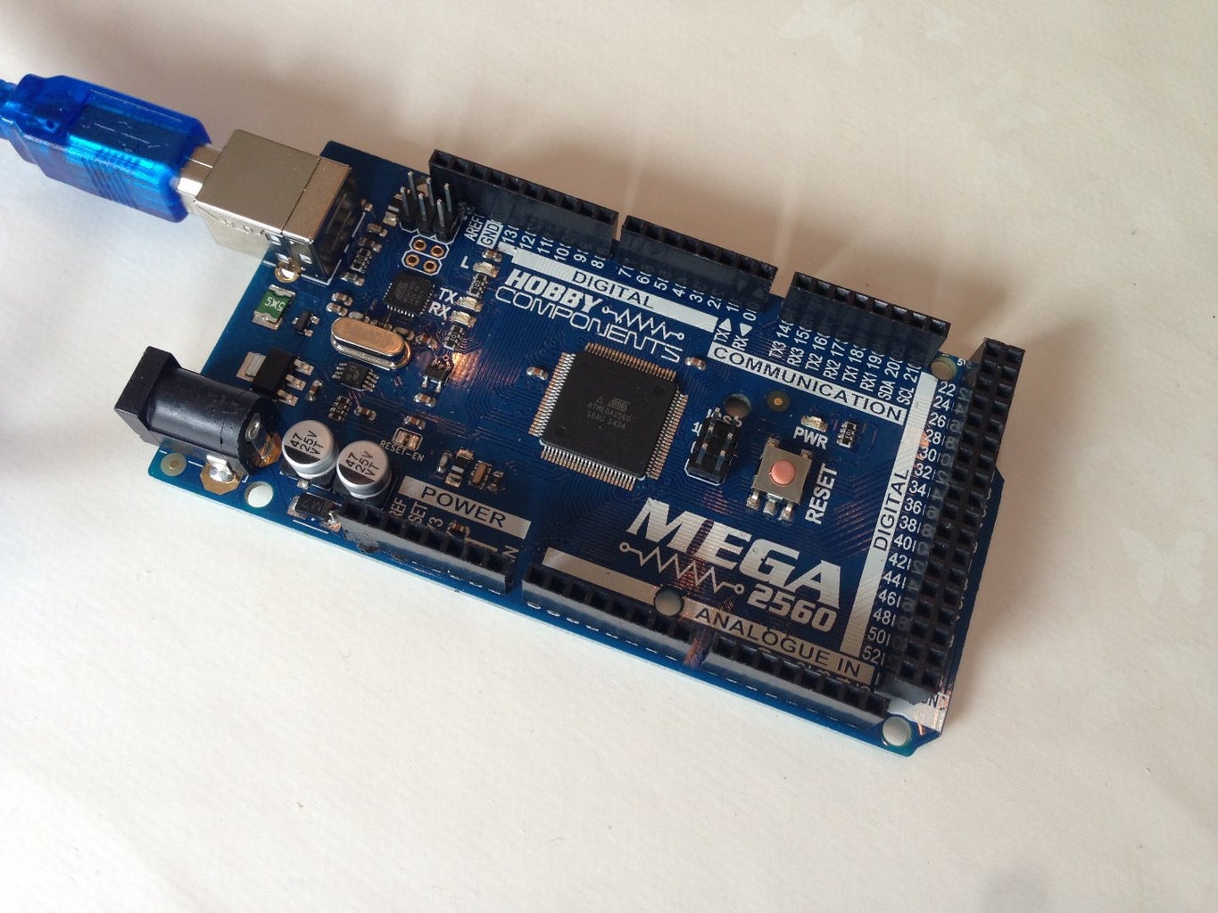
Arduino Mega 2560 Revision 3
I paid £14,49 + shipping £2,94 = 17,43 - that is grossly overprized as you can find Arduino + Ramps board for this Price almost. You do not want to buy these in china as it takes a month (if you are Lucky) to get a replace if there is a failure.
This is the Arduino Mega 2560 platform where you put your Ramps 1.4 control board onto it. This Card can be used for all sorts of fun stuff, and can be reused for bigger 3Dprinters and maybe even CNCs.RAMPS 1.4 Control Board + 4X A4988 Stepstick Driver Modules
I paid £10.98 with free shipping on eBay. (item: 81223071728) - This is in China which I can't really recommend as the potential wait is long. Potential savings are awesome though!
This is the 3D printer extenstion/platform for our Arduino Mega 2560.
The Ramps 1.4 control board is just interface where everything else is connected to.
We have/need a Driver Module for each stepper motor. That Means 1 for X, Y, Z and Extruder motor, so 4 in all. If we want to, we can use 2 drives and 2 motors for the Z axis or maybe 2 Extruders, which would require 5 Drivers.
This can be reused for bigger 3Dprinters and CNCs at a later date. Bigger has limits as the Driver modules only deliver up to 1amp each.3D Printer - Filament Extruder Feeder Kit with Nema 17 Motor and Driver Gear
I picked the Filament size 1,75mm. I have the left side Feeder kit.
I paid £19,95 + £6,90 shipping = £26,85 (item: 201242249437)
This is the one stepper we have to buy as the motors from the CD/DVD drives are not powerfull enough.
This one forces the filament into the hotend.
The "Feed Kit" is the black solid plastic thing attached directly to the Nema 17 motor which Includes grooved roller bearing, Spring and fixing screws.
You can buy an extra Feeder Kit if you want for multiple sizes Filament extra kit.(pretty expensive kit though).
I use this particular motor + kit as it can be reused for a larger 3D printer down the road and because I don't want to experient with creating my own feeder kit.
It is called a "Bowden extruder" setup. You can find it cheaper but just make sure you can figure out how to create or fit on the parts needed to create an Extruder.
NOTE: This extruder is far from perfect and you want a more powerfull stepper motor for a real printer extruder. You also nee to come up with some sort of contraption to keep the bowden cable attached to this Extruder.PFTF - Teflon tubing.
Guides the platic filament from out Filament Extruder and up into our Hot-end. I ended up buying a 1m PFTF tube with fittings on the ends.
3D Printer Filament PLA or ABS 1,75mm (I havn't tested it much yet)
I paid £6,90 (item: 200955198928) - It was shipped with my part 2 (Extruder kit)
This is the plastic "wire" that gets used as material. You can buy this in different colors and different sizes. Normal sizes are 3mm and 1,75mm.
The Price I paid is high for the amount of material I recieved, but it is cheaper than buying two Pounds and I was very uncertain wheter I would actually use it all. I didn't really know the differences between the two either.
I'll recommend buying ABS and not PLA and make an Acrylic Printed bed for this project.3D Printer Hotend MK7 MK8 Noozle 03 and 0,4 Thermistor and Cartriged (I know it is spelled wrong)
I paid £14,29 + £3,93 in shipping = £18,22 (item: 121305643475) (not the best quality)
This is the 3D centric parts of our machine. This is the bundle you unmount if you have buildt a combined CNC and 3D printer.
The Cartridge contains the heater-element and is inserted into the aluminum end of the head. It heats up the hotend and can melt the plastic which gets squeezed through the noozle. This package include 2 noozles: 0,3 and 0,4mm.
The Thermistor is used to measure the temperature of the Hotend.
The "threadded" rod is actually hollow and contains the "melting" chamber. Some models come with affixed heatsinks. We make our own.
You can buy all sort of J-heads.
My specific hotend never showed up, and I ended up getting a refund and found some other seller. The first seller immediately gave a refund, so I had no problems in that regard.5 X Resitors, Compact Ceramic, 22R 7W Part # WELWYN SQP7S-22RJB15
I paid £3,21 + £2,95 in shipping = £6,16 (item: 390813570865)
I only really needed 2 of these. They are to going to be placed under our hotbed. They can warm it up sufficiently for our need. We attach these using Kapton tape.
Look locally for better prices if you know an Electronics shop. Or just spend more time on eBay than me.
NOTE: I recommend using a piece of Acrylic to print ABS on, so these aren't needed.2x Thermistor 100K
These are used to measure the temperature near the hot end and on our hotbed.
I paid £1,49 + free shipping. (item: 301299947038)
You can get these cheaper but I bought some that came attached to the wire with some protective wrappings etc. as I hope it will be more endurable that way.
NOTE: These Thermistors are only rated up to 200c. It is propably due to the insolation material used which might catch fire or melt if the temperature goes above 200c. That Means these can only be used for Heated bed, which I recommend not using for this project.Kapton tape
This is basically tape that can withstand very hot temperatures.
We need this to attach our thermistors to the hot end. It comes from £1 and up, depending on Width and legth you buy.
Beware that many sellers actually Sells "Koptan" and not "Kapton". Read the description and look at the images carefully. Also check it when you recieve it.Endstop Switch for CNC 3D Printer RAMPS1.4
You do not have to buy these. You can either use the ones from DVD drive or configure in software. Listed here to make the listings complete.
Found them at £6 with free shipping - item: 351156547800.
I did not use any for the small printer. Remember what I wrote about basic limit switches I wrote earlier.
Step 3: Decommissioning and Salvaging Part From Our CD/DVD Drives


Parts we want to salvage from our CD/DVD drives
We want 3x laser head slider (DVD-bed) mechanismwithstepper motors, including the frame it is mounted on. This included the center part, rails, motor and the bed it is attached to. See Photos.
From now on I will call it:
- The center moving part as: DVD-bed
- Motor with 4 wires: Stepper motor
- The entire frame all the parts are mounted on: DVD-frame
Be carefull not to remove any parts which function is to hold the metal rods in place. When stripping the moving DVD-bed you should again be carefull not to remove any parts that function as any sort of grip on the metal rods.
We are also going to use some of the metal covers to build our framework. Feel free to use Wood, acrylic or some other stuff instead.
Disassembly
It is pretty straight forward to disassemble a CD/DVD drive.
- You use a paperclip or similar to press into the small hole in the front to open the drive-bay. I learned that drives without this hole is most likely to contain DC motors. We can't use DC motors for this project.
- Then loosen the front plastic bezel which is held in place with some small retention taps you need to depress.
- Remove the 4 screws at the bottom and remove the lower shield.
- Remove the upper shield. Some of these are connected to some of the PCB parts, so don't rib it off with too much force.
- Next you go about Carefully removing the bed where the stepper motor is mounted.
All my first batch CD/DVD drives had stepper motors. Stepper motors have 4 wires (as a small ribbon) while DC motors have 2 wires. We need the Stepper motor version.
I got a second batch and only 1 had a Stepper motor! :( Only indication I've seen is how the DC motors seems to lack the tiny hole you can use to open the drive-bay. One of the models with DC motor had a hole though.
All my drives were very old IDE drives.
Some of the below info on Stepper motors were copied or at least inspired by/from here.
3 of my stepper motors showed to be a model PL15S-020, which turns out to be a common and very well documented bipolar stepper motor. Data sheet for this model. (opens a pdf file)
This particular stepper motor does 20 steps per revolution, and the lead screw has a pitch of 3mm per revolution. This Means that each step of the stepper equals a 150 micron displacement of the laser head.
I am going to run mine at 1/16 microsteps, as it did not Work with full steps as I originally had intended.
The resistance through the connectors and coils were around 10-11 ohms on these.
I've read around the net that it is best to have 2 identical drives for the X and Y axis. I have seen builds with a bunch of mixed drives though. I guess it can be configured in software...
Why do I want to use 3 CD/DVD drives?
I have read that people had issues with the Z axis (up) being too heavy for 1 DVD stepper motor. I found a possible solution to be a single floppy drive stepper motor instead, which should Work for some reason I don't know. Using a floppy drive motor is going to decrease the Z height by 1-2cm, which I did not want.
I thought about using 2 CD/DVD motors for the Z axis but I read that you would still need a counterweigh, so I decided to just use 1 CD/DVD motor and use a counterweight to help it.
I mount the X-axis DVD-frame on the Z-axis DVD-frame as I had reservations about adding all that weight on the X-axis motor, which I had no way to unburden since it moves sideways.
Feel free to do otherwise.
I can see some guides says "keep endstops", so do that if you can. None of my drives had any of these though.
I have found it can be configured in the software, so I am going to do that for this 3D printer.
I later found that the endstops weren't really placed near the drivebed but usually placed in the front of the PCB. A Little switch you can depress. Some floppy drives have complete end-stops including a small pcb with all necessary Electronics. I even found some optical ones, so good hunting!
This instructable is not going into details about salvaged endstops, as I'm new to the Electronics and didn't want to short out anything.
Cutting off protrusions and drilling mounholes
I cut off as many protrusions I could from both the bottom and top side of the bed. I needed somewhat flat areas as I am going to bolt through and need something flat to fix the washers up against. I should had taking some "before" images, but I totally forgot.
Be carefull not to remove too much as you might end up with a loose drive-bed.
See the Photos.
You can also see the holes I drilled through each bed. They are 4mm but 3mm would be fine too I guess.
Step 4: Stepper Motors: Soldering Wires and Figuring Out Pin Out.


Finding coil pairs
This is where we are going to put our Multimeter to good use. I put my selector (round selector Wheel) on 200 ohm and tested two pins at a time. When I found a configuration with a measurable resistance (something shows on the multimeter), it meant I had found a pair connected to the same coils.
NOTE: the correct way to do it is to test for continuity where your multimeter beep/whine when there is a connection between the two wires.
Se Photos for how I did the solderings.
I had 3 matching motor: PL15S-020
The resistance through the coils of the PL15S-020 is 10-11 ohm. Mentioning this as one of my other motors had the exact same dimensions and the same resistance while others were much longer and had 20ohm resistance instead. I don't know how it translate into real World use. I thought the longer motors would make it possible to create bigger printed objects, but they did not make for a larger movement range.
Soldering
I detached the stepper motors from the drive-caddies. Put one in my 3rd hand crocodile jaw and desoldered the four pins. Next I used the second crocodile jaw to hold the wire and aligned it in such a way, that i didn't have to manually control it as well. Meaning I could focus on controlling my soldering iron and tin.
I kept the flat wire-strip as there are some sensitive copper wires just below it, going down to the coils. It also prevents solder from finding its way down into the coil itself.
I soldered my wire directly onto the motor and cut short the flat wire-strip. I have seen other people solder their wires to the far end of the wire-strip instead. Do what you find Works best for you. Just make sure the wires/soldering doesn't get in the way of mechanically using the motors in the motor-bed afterwards - might be some Space restraints.
I used some wire from computer fans. I used the same color wires for each pair on the motors. Ie: 2 yellow and 2 black on a motor where the 2 read wires is connected to the same coil.
See Photos to see what I'm talking about.
Testing for short circuit
After soldering I redid the testing to ensure I hadn't just made a short. Meaning I tested to make sure there is no connecting between the two pairs of wires.
If a short occurs you remove the tin by melting it and sucking it up using the Soldering sucker and redo the soldering of the affected wires.
Do strap up the wires using some wire-zippers to avoid ripping them Loose while we build our printer (I did that before zipping them up). You also just want to zip-them up to provide strain relief - see Photos.
Step 5: Creating 3D Printer Framework From DVD Chassis and Parts


Creating a mounting bed and mounting the "Y" stepper/frame.
First the therminology I'm going to be using:
- I'm calling the entire metal Construction from the CD/DVD drives for "DVD-frame"
- The center moving part will be known as "DVD-bed"
- Front is when the horizontal dvd-bed is moving towards and away from you. This is your Y-axis.
Remember I said we needed to keep some of the metal plates from our CD/DVD drives? Try if you can find one that is somewhat level without a lot of grooves or other similar things.
Y-axis
I picked a fitting specimen and cut a hole 75mm long and 55mm wide. The size in cm/mm itself isn't what matters. What matters is that it just needs to be big enough for the 4mm rods that goes through the moving bed and up through the bottom of our hotbed (hotbed/hotplate is the surface/plate our 3D object is created on) to pass through for the entire Y movement range, which is about 4cm long. If you just make the hole about as long as the hole in the DVD-frame, you are sure it is good.
In hindsight I should have picked a longer case - I had to enlarge my platform some.
When I started this instructable I had planned to make detailed Measurements and diagrams for the entire build-frame, but it is almost impossible to do so as all the DVD-frames are different. Even the ones with same stepper motors on are different. The ends of the individual DVD-frames are not even the same!
I placed the DVD frame as far towards the front as possible with the motor close to the front edge. Motor facing forward is in order for the heatbed to be as far towards the back of the assembly, away from the motor, when in the "home" posistion (see a bit farther Down)
DVD-frame corner "bracers"
I used a DVD bottom plate to cut out some 15x15mm plates. I used the squares on each side of the DVD frame in each corner, and drilled some holes in each of them. Actually drilled it before cutting them out.
You can see in the Photos how I use these cutouts to fix the drive-part to the metal-housing.
You might find it easier to use some other things. I didn't find the round normal washers to be very good.
Z-Axis
Our up and down axis.
I fixed a piece of angled aluminum, as wide as the platform, at the end of the Z-axis bed. I drilled two holes and cut away the metal between. This provides some level of adjustment.
You can't use these for adjustment later in the projects due to the rigid frame we are going to make.
For final adjustments, we are going to adjust directly on the bracket where the Hot-end is attached.
Before attaching the piece to the bed we drill holes for our Z-axis dvd-frame and an extra holes near the ends for the vertical aluminium pieces.
At each ends of the bracket I cut grooves into the DVD-case. Into the top and sides of it, in order to insert a piece of angled aluinium in each side. I drilled holes in them for bolts to go through both the sides into the DVD-case and the fronts to go through the horizontal-mounted bracket. (see Photos)
On some of the pictures I have installed a normal "rod" of aluminum in the top. I later put in an angled piece in the top, identical to the bottom one. I extended this by a 4cm wide aluminium in order to attach our counterweight for the Z-axis.
I also planned to put a bolt through this if I needed to adjust the alignment of the vertical axis. Turned out I didn't need this and it would have required some changes or a threadded hole to do it. I didn't want to tap it (to make inner threads in the hole) as most people don't have a set like that.
Z-Axis moving-bed
I prepared the z-bed by removing any protrusions and drilled 3 holes through it for bolt through. I cut a piece of 4cm wide aluminium with a lenght to match the Width of the dvd-bed used for X-axis.
I just mounted it centered on the bed, so didn't make any special height adjustments on it. I did make the holes a bit larger than 4mm as a Means to adjust it a bit.
I drilled a/some holes in the top to fix some wires/tubes from the hot-head (not shown on all images).
X-Axis
The X-axis frame is simply center-mounted on the aluminium piece we just attached to our Z-axis moving bed. I used spring-washers as a means to do very fine adjustments if needed (turned out to be a unneeded).
I needed a few bolts and washers to make sure nothing went up against the Z-axis pieces.
The very small piece of aluminium you can see on the x-bed, on some images, is simply there as I wanted to visualize the Work.
I cut a piece of 4cm aluminium almost the same length as the Width of the X-axis bed and fixedit on the x-bed with the bottom edge flush with the lower edge of the X-frame.
I fixed two pieces of angled aluminium to this longer pieces. The lower one is holding the J-head, while the upper head can help hold the fan and the Bowden tube going down to/into the hot head.
Home Position
This part is explained in better detailed later on.
Home posistion, which is also the start posistion is when you sit in front of the printer and look at it. Then the bed is as far away from you as possibe, meaning the hotend/nozzle is as far towards the front of the hotbed as possible.
The Nozzle's home posistion is the front (Closes to you) left hand corner with the various beds as far away from their respective motors as possible.
End stops
I'm not going to use endstops for this little printer as I did not get any on hands while working on it.
Step 6: Heated Bed


Heatedbed, hotbed or heat bed or what ever you call it. The thing has many names.
RepRapWiki on Heated Bed.
Why use a Heated Bed?
The idea is pretty simple actually: if you print a hot plastic material on a Cold/semi-cold surface the plastic is going to contract which is going to lead to distortions or the printed object might pop off entirely.
You do not want to keep the layers molten though as it must be able to sustain layers you build on top. I've read that 60c is a good temperature for a Heated Bed - when printing PLA. If you prin ABS on Glass you want the bed at 110c!
For this build I recommend using ABS on Cold Acrylic plate as the ABS Sticks very well to Acrylic material.
Building the Y-axis / Heated Bed
As with the other Axis' I've flattened the DVD-bed, drilled 3x 4mm holes and attached some 4mm bolts to the bed with a few nuts. These nuts functions as spacers up to the aluminium plate which will function as the lower part of our Heated Bed.
The Aluminium plate is 4cm wide and 75mm long with a 3mm hole drilled near each corner. Be sure you have clearence below the plate for the head of the 3mm bolt you are going to use at each corner. I extended my Heated bed further outwards, so it isn't entirely centered.
I did this to be sure the Nozzle of the Hotend wouldn't get in contact with the nuts on top.
Creating the heating element
I'll recommend not Building a heated bed, but I keep the instructions just in case.
I'm going to use 2 Ceramic resistors, 22R 7W (SQP7S-22RJB15). One would be enough, but I'm going to use two in parallell.
I lined them up to each other, put some heatshrink on the exposed "legs" between the two - to avoid shorts if they touched the Heated Bed. I then wrapped the overlapping 'legs' around each other and soldered them together.
I soldered a some wire on each of the legs and covered it all in heatshrink.
See Photos
I tested the parts using a simple 12v 1.5a adapter. I had an IR reader which couldn't readout from the surface of the Ceramics but one of them heated up the piece of aluinum to 120c in a few minutes, so Watch your fingers and put it on something that can handle the heat!
Creating a temperature sensor
You don't need this if you just use Acrylic plate and print using ABS.
We are going to use a standard 100K Thermistor as our temperature sensor.
I'm actually using the one that came with my hot-end as it wasn't wrapped in any sort of protective materials needed for the Hot End - I bought an assembled Thermistor with included protections against the much hotter Hot End.
Before starting I measured the resistance which showed at 110k or so. I guess that is ok..
I twined each leg together with some wire, soldered it and put on heatshrink. Be sure no parts of the legs touch each other as it will cause a short and thus incorrect readings. It doesn't matter what color wire you are using as there is not +/- to the sensor.
I put a small piece of Kapton tape around the Thermistor head and a bit of the legs to avoid shorts with contact to the Heated Bed.
Be sure to redo the measuring with the Multiemter to check for shorts.
Putting it all together
I made a small indentation in the top aluminum piece where I wanted the Thermistor. I originally planned to put it in the center, but changed my mind.
Fix everything Down tight, including the wires. Don't treat the soldered joints as mechanical fixpoints as solderings are not meant to Work that way.
I put a piece of heatshrink around all the wires and led the wires out the hole I made in the center below the Z-axis platform - see Photos.
Put on the springs, the top plate, washers and bolts and you'r done.
Step 7: Powersupply


To keep costs down I have found and old standard ATX powersupply unit (PSU from now on) I am going to use. My particular specimen is 310Watt. The important part however is not the Wattage, but the amperage on the 12V. My particular model has, or can deliver, 17Amp on the +12V. Seems that we in general would need 16-17amp on 12v for a "normal" 3D printer, meaning with Nema stepper motors all around and a much larger heat-bed.
It is important as we only feed 12V to the Ramps 1.4 boardwhich in turn will provide power for the connected units.
The Arduino Mega 2560 r3 board is going to be powered by USB (or maybe through the Ramps board) - a bit unclear to me really.
After writing all this, I found a nice wiki on Choosing a Power Supply for your RepRap.
Preparing our PSU
First a Word of warning: Do not, NOT EVER, open the PSU while the power is on. Even when you have turned the power off, some parts of the internal PSU might cause lethal jolts, so do this at your own risk! If you want to make sure, you need to turn the power off and let the PSU decharge for 2 days before opening it.
In order to manually force the PSU to be switched on we have to short out two pins on the big 20/24 pins cable. See images. I had an "adapter" which is just a plug which shorts it out. You can also modify it with an on-off plug, but that goes beyond the scope of this instrucable.
However you do it, you just make sure it doesn't fall out, so make sure the wire doesn't fall out by taping it in place using some tape with a strong adhesive.
Most newer PSUs doesn't start up even when shorted unless there is some additional load on it, so hook up a fan, old harddrive or something to test it turns on.
Looking at PSU innards 12v leads
Unless you buy a really expensive PSU with multiple physical 12V rails you will find that all the 12V yellow wires are connected to the same point inside the PSU.
You can see in the image how all but two of the yellow wires are soldered to the same spot. The last 2 yellow wires are going out through the 24pin cable.
This means it doesn't matter which of the yeloow wires we are going to use.
My PSU only has 4 main bundles of wires including the 24pin cable.
Making 12V connections for our Ramps board
The Ramps 1.4 board is designed with a +/- connector for a 12V up to 11Amp (12v x 11a = 132Watt) and a +/- 12V up to 5amp (12v x 5amp = 60watt) power supply.
The Ramps use these inputs to feed all connected items like motors, hotbed, fans etc.
The 12v 11amp is stricly for the Heatbed only. All the rest of our gear is powered from the 12v 5amp input.
It is important to understand that all the yellow wires delivers 12V. The Amperage is the listing on how much current the Ramps 1.4 might draw from the PSU in 12V. The PSU is not going to overload the RAMPS with any excessive Amps.
I'm stating this, as I've seen many people worrying about using a PSU with a high wattage/amp rating. It doesn't work that way.
So: Amperage is just the max rating the Ramps 1.4 board might draw from the PSU. The Amperage listed on the PSU is how much 12V Amperage the PSU can deliver.
Preparing and connecting our wires
The reason why we use more than just 1 wire for the 11Amp plug is because if we used just 1 wire it might heat up some. We are at a very low wattage here, but better safe than sorry.
A single 18 Gauge /1,2mm wire can handle up to 12V 10Amp. So, using 2 wires we are far within the comfortable limits and a single wire on the 5v is ample as well. (I'm not an electrician, so I'm really just quoting my findings)
If you want to do some conversions on your own, you find the overview on the above link and a SWG/mm calculator here.
When Building my larger real 3D printer I looked i up Again and found a US safety regulation for shipping where they use 12v (at least for the paper I found) and using a 1.5mm2 wire is plenty for everything below 20amp. No harm in being on the safe side and use 2 though.
12V 11Amp cable
I'm going to use the 2 yellow and 2 Black that goes to my 4pin (old style P4 cpu plug). I cut off the plug, strip the last 1cm of each wire and twist both the yellows together and the same for the blacks.
The yellow goes into the "top" most input. The one that is going to sit next to the area marked as D8 on the PCB of the Ramps board. The black wires are placed next to the yellow ones. See Photos.
12V 5A cable.
I have a wire with only 2 Sata power cables. I cut that to the same length as the 12v 11A cable. I connect the yellow wire next to the allready attached black wires and twist the two (new) black wires and place them into the last spot in he connector. See the Photos.
I use both black wires as I would have to remove one of them otherwise.
Sorting the rest of the wires
You are going to have 1 or 2 Loose wires now. You have to make sure they don't short out something so either cut it off from inside the PSU or insolate the ends with heatshrink or something.
I have two loose wires as this particular PSU delivers 3.3v to Sata powers, aside from the standard 5v. Not all older PSUs does that. Molex plugs only needs 4 wires as they do not use 3.3v.
The two connectors I've put on the Loose wires are the Wago connectors I mentioned in the parts list.
Remember to check your result using a Multimeter. (I connected the plugs in reverse in my Multimeter, which is the reason why the display reads "-11.66" instead of just "11.66") The rather low voltage listed is due to almost no load being placed on the PSU. I later added a resistor similar to the one I use for the heat-bed, between the +5 and GND which resulted in a perfect 12v reading :)
Long instruction to using ATX powersupply for this, if you feel like delving more on the subject.
After writing all this I extended my wires as the short cable-run was annoying.
Another approach is to use the wires from the large 20-24 connector. It has everything we need and some.
Step 8: Arduino Mega 2560 R3 Setup.

There is not much to know or say about this board, for our use, aside from it being the computational base for our 3D printer.
You can read a lot about it on the official site where you also can read the Getting started guide - direct link to the Windows getting started guide.
Software - Arduino Environment
To get started we download the latest official software (1.6.1 as of this writing - just get the newest on always). (previous versions, if you want 1.0.6 version for some reason)
When downloaded I just double-clicked it to start the installation and went with all default options. Choose install and trust the USB driver installation pop-ups that might come on your system.
Connecting and testing the Mega 2560 to the Computer
Simply just insert the USB cable into the Mega and your PC. You do not need a PSU to power it. The computer will install the necessary drivers from the software you installed above. You might even see which COM port it is installed on/as, which can be helpfull later - but not critical by any Means.
If your software is using localized langauge, which in my case is Danish, and I want it to be in English, as it is easier for me regarding tutorials, you can change the language:
- File -> Preferences -> Editor Language -> Choose the language you prefer.Close and open Arduino software Again.Connection settings
Initial setup of Mega
- Select your Arduino model: Tools -> Board -> Arduino Mega or Mega 2560
Note: it remembers this selection for future uses. - Select Com port it is connected on: Tools -> Ports -> COM3 (Arduino Mega or Mega 2560)
Note 1: the port number on your system might differ.
Note 2: If it is unclear which one to choose, you should note the listed COM numbers and then unplug the Mega. Take a new look in Tools -> Ports and see which ones are in use by other items and which one is missing.
Verify Mega functionality with a bit of example code
- Open the LED blink example sketch:
File > Examples > 1.Basics > Blink
A new identical window will open op, but now containing some code.
You can close the first window. - Upload program: Press the arrow that points to the right to upload the code to the Mega.
The code is compiled, uploaded and activated. One of the LEDs on the Mega is now blinking
Unplug your Arduino and continue reading.
Step 9: Ramps 1.4 + A4988 Driver Modules - Description


This step provides a short description on each part of the Ramps 1.4
RAMPS 1.4 Control Board + 4X A4988 Stepstick Driver Modules
RAMPS is short for "RepRap Arduino Mega Pololu Shield" and the 1.4 is version number. It is the "Heart" of any RepRap Machine. It's actually computational inert in itself, but function like one big interface (expansion board) for adding all kinds of stuff, like stepper drivers, motors, hot end and so on, to our Mega 2560 board, which is the brains in the operation.
RAMPS should be powered with a 12V Power supply which can supply a minimum of 5A, an additional 11A if you plan to use a Heated Bed.
For more detailed information on RAMPS 1.4 refer to the RepRap Wiki:
http://www.reprap.org/wiki/RAMPS_1.4 or Arduino Mega Pololu Shield
Description
I choose the RAMPS solution as everything is pretty much jammed into this addon shield to the Arduino Mega 2560 R3 board with tittle or no need to add all sorts of Electronics components.
The RAMPS board itself function as the base for controlling everything we need in regards to 3D printing: extruder, motors, heat-bed, hot end, temperaturs, fans and even an LCD display you can buy as an addon.
I later bought an LCD and it is really nice :)
In order to control our stepper motors we need the small A4988 Stepper Motor Driver Board.
Feel free to read the A4988 datasheet. I must admit I don't understand much of that datasheet.
Warning: Connecting or disconnecting a stepper motor while the driver is powered can destroy the driver. (More generally, rewiring anything while it is powered is asking for trouble.)
Features of driver boards.
These Things comes with a list a mile long, but here are the important ones for now.
•Maximum output current is 1A - this makes it ideal for small stepper motors and it is the reason why you might have seen other 3D printers with much larger Motor Drive boards. They can provide up to 2a safely though.
•Five different step resolutions: full-step, half-step, quarter-step, eighth-step, and sixteenth-step
•Adjustable current control lets you set the maximum current output with a potentiometer, which lets you use voltages above your stepper motor’s rated voltage toachieve higher step rates.
•Over-temperature thermal shutdown, under-voltage lockout, and crossover-current protection
•Short-to-ground and shorted-load protection
Before usage / Preparing for usage
Check for any bent pins or other obvious damage. If you find any pins that has been bendt some, you can in almost all cases straighten them up using your fingernail or similar small tool.
The motor drive boards are each placed on two rows of female connectors. Between these connectors are 6 male pins with room for a total of 3 jumpers. We are not going to use any jumpers for our setup, as we use full steps. This is the place to make any such settings though. See diagram in image for all configurations options.
Gently install 4 of our driver boards in X, Y, Z and E0. The small potentiometers are placed farthest away from the power-input connectors. Leave E1 empty. After installing the driver boards you should put on the small heatsinks that came with the package.
Wiring up
One of the very appealing reasons to use this particular board is how we connect it with a few 12v input wires, as previously described in the Powersupply step, and then everything connected to the Ramps 1.4 is powered through it, so we do not have to deal with individual power leads or custom powerbricks or any of the other multitude of solutions I've seen.
See the images where you will find the custom Ramps 1.4 wiring image I made for this.
For a more general wiring manual, I can highly recommend the one at nextdayreprap.co.uk.
The downside is the 1-2 amp limitation of the driver boards.
After Building my real printer I bought 2x SilentStepSticks for my X and Y axis. Worth every penny, but don't go spend Money on that before you get that far - if you choose to do so
I also made an Instructable for those Sticks: Install and configure SilentStepStick in RAMPS - TMC2100 Schrittmotortreiber
Power input
As we just discussed, the power input is simply two 12v mains. One can Draw up to 11A on 12v and the other up to 5A on 12V. We are not going anywhere near this, but it is nice to know as it does put a limit on what we can connect to this board.
Power output
Every item connected to the board is powered through one of their respective wires. It is very important that we double check every connection we make to avoid short-wiring it.
The D8, D9 and D10 are terminals for DC output to our hot-bed, fan for hot-end and hot-end.
Stepper motors
Our DVD stepper motors, which we color-coded in pairs, must be connected in pairs. Ie. first you connect the 2 blacks on pin 2B and 2A (first two pins), and the two yellow wires on pin 1A and 1B (two last pins).
If the motor drives the platform the wrong way, you can shift around the pairs. IMPORTANT!!: everything must be entirely shut down and powered off. Meaning power-plug out of wall, 12V input power connector removed from the Ramps 1.4 and USB plug unplugged before you unplug any pins on the Ramps board or this is a sure way to fry the Ramps board, or at least the Stepper driver board.
You can invert the direction in the firmware instead. Described in the next step of this instrucable.
Temperature probes
We connect our Temperature probes, to the pins marked with T0 for our Hot-end and T1 for our Hot-bed. You can add a third one to the T2 if you feel like it.
Endstops - Home posistion
You might have none, 3 or 6, or some other number.
Remember how I talked about the home placement? When you sit in front of the 3D printer and look at it:
The hot-end nozzle must be as close as possible to the hot-bed's edge closest to you and to the left hand edge of the hot-bed.
The nozzle must be as close as possible to the bed without actually touching it. You can test it by placing a standard print paper on the hot-bed. When you need to give a slight tug or two to remove the paper, then the nozzle is down far enough.
You can fine tune these things in the software.
Endstops - When the home position has been achieved.
In this posistion we install our endstops. Meaning up install them in a place that will activate them when your printer is at home posistion.
You do not have to use endstops, but if you do not you might have to do a manual calibration before each print. At least for this little printer.
If you have more endstops you can place them in the MAX end.
If you have all 6 endsops installed correctly the printer is self calibrating as long as everything is screwed down tight and stays in place.
Real self-calibration can only be achieved if you Invest in items like a Proximity sensor or Force Sensors, but that is for another instructable.
Step 10: Assemble/Firmware on Mega 2560 and Ramps 1.4 Board


It is assumed you have installed the Arduino software ("Arduino IDE" from now on) and prepared your powersource in the previous steps.
Assemble Mega 2560 R3 and Ramps 1.4
Unplug the Mega 2560 board and disconnect any powercords you might have onto the Ramps 1.4.
I removed the motor driver boards as I found I needed to lay down some rather firm, but even, pressure on top of the Ramps 1.4 board to make it connect properly.
You need to be really carefull as there are a lot of pins that all needs to go down into the female plugs on the Ramps 1.4 board. I had a handfull of bent pins that was noticeable and the entire upper row had to be gently nudged inwards as well!
I also needed to shorten some of the pins under powerconnector on the RAMPS 1.4 as they lifte up from touching down on the power-barrel on the Mega 2560 r3 board. It doesn't matter that they touch, but my board was lifted up a lot!
On the positive side though, is the fact that the RAMPS board can only be installed one way.
After assembly you:
- Insert the green powerconnector (12v11a/12v5amp) into Ramps 1.4.
- Check the wires corresponds to the input + and -
- Turn on the PSU.
- Connect the USB to your computer.
Doesn't matter what what sequence you do 3 and 4..
Warnings
Reversing +/- or otherwise incorrectly connecting power can destroy your electronics and cause fire hazard.
Incorrectly inserting stepper drivers will destroy your electronics and cause a fire risk.
Always make sure power and USB is disconnected when removing or adjusting stepper drivers. Always make sure to insert drivers in correct orientation and in the socket correctly. Small adjustable potentiometer away from powerinput.
The endstop pins might have a different layout on your endstops or board, so make sure to wire them correctly.
DON'T secure Arduino/RAMPS with conductive screws through both mounting holes. The screw may cut into the positive trace creating a HIGH current short.
Download software
We are going to use the RepRap Marlin (not a link to download, but actually a wiki with step-by-step instructions if you scroll Down to "figuring and compilation") software (it's actually a firmware) among the many other firmwares (a list only) out there.
We need to upload the firmware to the Mega 2560 R3 board before we can start taking advantage of our Ramps 1.4 board. The Marlin firmware is code that turns the Mega 2560 r3 board into a 3D printer (basically).
There is a good description here, if you want some other angle than what I write.
Another person made a guide that I found usefull as well.
Get the Marlin Firmware
Go and download the Marlin 3D printer Firmware, which is version 1.0.2 as of this writing, and place it somewhere you can find it.
Click the Download Zip in the right hand side. See my images here if you can't find it.
The file you downloaded is named Marlin-Development.zip which will create a folder named Marlin-Development when you unpack it. Put it someplace convenient like the desktop.
Setup the Marlin Firmware in Arduino program
- From inside Arduino IDE: File -> Open
- Browse to your Marlin-Development folder and into the Marlin folder.
- Select and open the Configuration.h or Marlin.ino file (both opens a linked set of tabs/sketches, so it doesn't matter which one you choose).
- A new window opens containing the Marlin.ino. Close the other/old window.
- You have a lot of tabs in the open window. Select the Configratuin.h tab - see images.
Defining Motherboard as RAMPS 1.4 with accessories.
We need to define which Motherboard we are using. You can see all available board types in the boards.h file.
Many guides around the web tell us to either edit at boards. or pins file or similar, to define motherboard. We do not have to do that anymore. The variables we need are all placed in Configuration.h
- Configuration.h -> Press CTRL+F to open the find window and write RAMPS
- Click Find to find the line containing: #define MOTHERBOARD...
- Here we need to define our board as pr. definitions in the boards.h file. Aside from defining we are using a RAMPS board, it is the the devices connected to the D8 (Heat-bed), D9 (fan) and D10 (heater)we define here. E is for Extruder, F for Fan, B for Bed.
- Make sure the line reads: #define MOTHERBOARD BOARD_RAMPS_13_EFB
- Say we had two fans and no heatbed we would define the last part a EFF instead.
- Save the file if you made any changes.
Defining Baud rate, Extruders and Power Supply
Default baud rate is 250000 now. If it gives you any problems (with your computer) you can change it to 125000.
These steps are only for people WHO need to change it to the non-default 125000 configuration.
- Open Configuration.h
- Find the line containing #define BAUDRATE 250000 and put two slashes in front of it, like this:
// #define BAUDRATE 250000 - On a new line you write:
#define BAUDRATE 125000 - Save the file
Extruders are default defined as 1, so leave that alone.
Power Supply is configured as standard ATX. PSU can be defined as X-Box as well.
Defining Thermal Settings
Temperature sensors
There is a list with 20-25 different options for each sensor. Below the options is the list which defines our sensor inputs on the RAMPS 1.4 board.
Default defines SENSOR_0 with option 1 which Means it is a // 1 is 100k thermistor - best choice for EPCOS 100k (4.7k pullup) or in other words: the standard thermistor used for temperature Measurements for 3D printers (that I know).
The TEMP_SENSOR_0 is your Hot-end thermistor.
The other sensors are configured with option 0, which translates to being disabled.
#define TEMP_SENSOR_0 1
#define TEMP_SENSOR_1 0
#define TEMP_SENSOR_2 0
#define TEMP_SENSOR_3 0
#define TEMP_SENSOR_BED 1
Heater settings
We need to define minimum and maximum temperature of our Hot-end and Hot-bed
Minimal temperature
First is the Minimum settings, which are default at 5, which is just to test the Thermistor is working. Ie: to make sure wires aren't melted or otherwise damaged etc.
Comment out 1 ,2 and 3 as we don't have those.
You will get a compile error if you comment out the BED_MINTEMP (maybe only if it enabled under Temperature sensors). You can define MINTEMP as 0.
#define HEATER_0_MINTEMP 5
//#define HEATER_1_MINTEMP 5
//#define HEATER_2_MINTEMP 5
//#define HEATER_3_MINTEMP 5
#define BED_MINTEMP 5
Maximal temperature
Here we define maximum temperature for our Hot-end and Hot-bed.
Defaults:
Hot-end: 275
Hot-bed: 150
Comment out 1,2 and 3 as we do not have those (not sure you have to really)
If you print ABS, you want to do it around 230 degrees or so.
Remove the // on the line with BED_MAXTEMP if you install a heated bed.
#define HEATER_0_MAXTEMP 240
//#define HEATER_1_MAXTEMP 275
//#define HEATER_2_MAXTEMP 275
//#define HEATER_3_MAXTEMP 275
//#define BED_MAXTEMP 120
If you make any bigger changes, you must change the Preheat Constants way farther Down in the file where (use CTRL+F) Preheat for PLA is listed at 180 for hotend and 70 for bed and ABS is 240/110 respectively.
Preheat Constants
These are mostly relevant if you use an LCD display, as these settings will be listed as "Preheat PLA" and "Preheat ABS" in there.
It is a good idea to Insert a comment with the original temperatures so we don't forgot those.
#define PLA_PREHEAT_HOTEND_TEMP 180
#define PLA_PREHEAT_HPB_TEMP 70
#define PLA_PREHEAT_FAN_SPEED 255 // Insert Value between 0 and 255
#define ABS_PREHEAT_HOTEND_TEMP 240
#define ABS_PREHEAT_HPB_TEMP 110
#define ABS_PREHEAT_FAN_SPEED 255 // Insert Value between 0 and 255
Extruder settings
As default the Extruder is configured to not start unless the hot-end is at least 170c degrees. This function is enabled as default with PREVENT_DANGEROUS_EXTRUDE and a default definened minimum temperature at 170c.
I have uncommented these lines as I want to test the Extruder motor first without attaching the hot-end.
Remember to remove the slashes later on.
// #define PREVENT_DANGEROUS_EXTRUDE
// #define EXTRUDE_MINTEMP 170
Defining End-Stops
End stops are small contacts/switches placed at one or both ends of axis to tell the system it should stop. These can be used to automatically calibrate the printer for Home and end-posistions.
Some of the technical electronical parts of End stops are allready defined as the different PULLUPS resistor configurations. You can read about pull-up-resistors in the wiki.
I'm not all into the specifics so i'm leaving most settings at default for now.
One thing of importance though: there are Pullup resistors on the Arduino board, which can be used, so you do not have to solder anything in yourself.
If you do not install endstops, you need to remove the slashes in front of one or both lines according to your system. I removed both as I don't have any endstops.
#define DISABLE_MAX_ENDSTOPS
#define DISABLE_MIN_ENDSTOPS
You can also define which way the printer should move to get to home posision. Read in the Axis movement directions below.
Axis movement directions
There is no real way to know which way the beds are going to move, except to try it out. After connecting everything you move alle beds to the center position and move one of them a bit. If it move the wrong way, you can either change the configuraitons or swap the wire pairs on the RAMPS 1.4 - AFTER you have powered everything off and disconnected the USB as well.
If you just want to change the configurations file, you change false to true as fits your system:
// Invert the stepper direction. Change (or reverse the motor connector) if an axis goes the wrong way.
#define INVERT_X_DIR false
#define INVERT_Y_DIR false
#define INVERT_Z_DIR false
#define INVERT_E0_DIR false
After your have configured the motors to move the right way, you should configure which way the motors have to move to get to the home position:
// Sets direction of endstops when homing; 1=MAX, -1=MIN
If a endstop is configured to be at the 0 position for that axis, the setting here needs to be -1. Otherwise, it needs to be 1.
#define X_HOME_DIR -1
#define Y_HOME_DIR -1
#define Z_HOME_DIR -1
I don't think you would ever really need to change this?!
Printer printing area
This defines how large an area we can print on. It is listed as 200mm in each direction as default, which is rather much more than our printer can do. Our machine can do around 40mm in each direction. I'll set it at 37, just to start at a safe distance.
// Travel limits after homing (units are in mm)
#define X_MIN_POS 0
#define Y_MIN_POS 0
#define Z_MIN_POS 0
#define X_MAX_POS 37
#define Y_MAX_POS 37
#define Z_MAX_POS 37
You can also define bed-leveling but you have to play with that on your own printer to make any sense of it.
If you use a floppy drive for Z axis it is around 15mm or so.
Movement Settings
We need to define how many steps the motors needs to make in order to move the beds 1mm.
We will need to use the values as calculated for the different printer axes and extruder. The order is {X, Y, Z, E}
//#define DEFAULT_AXIS_STEPS_PER_UNIT {80,80,4000,500}
#define DEFAULT_AXIS_STEPS_PER_UNIT {215.12,215.12,8034.69,196.52}
We define the fastest mm/s the printer is allowed to move. .
//#define DEFAULT_MAX_FEEDRATE {300, 300, 5, 25}
#define DEFAULT_MAX_FEEDRATE {100, 100, 2, 25}
We need to tune this. Listed is the default settings.
//#define DEFAULT_MAX_ACCELERATION {3000,3000,100,10000}
#define DEFAULT_MAX_ACCELERATION {200,200,50,5000}
We need to define how fast our printer is allowed to accellerate. The default for all 3 are 3000, but I change that to 100 to start up easy.
#define DEFAULT_ACCELERATION 100
#define DEFAULT_RETRACT_ACCELERATION 100
#define DEFAULT_TRAVEL_ACCELERATION 100
Upload the firmware to the printer
Press the "tick" (if that is the Word) icon to the left of the arrow icon to verify the code. If it makes an error you need to find it and correct it. It is most likely a typo or maybe an extra \ or similar.
If it does give an error but not showing you anything, you can choose to copy it and paste it into notepad or similar, to see what the error is.
You can press the arrow-icon to upload the configuration to your printer.
A common error I've done was being connected to my printer with Pronterface (or another USB controller program) as Arduino can't connect to it in that case.
Step 11: Verify Stepper Motor Works


Testing and usage
Cura
We are going to use Cura to manage our model files. It has included a "slicer" which is the part that generates the gcode, which our printer in turn use to know how to move around and print what we want.
Pronterface
We are going to use Pronterface to see if our motors move the right way. The latest version for Windows, which I'm going to use, is from febuary 2015.
Position the printer axis manually at the center of each axis.
Power up the printer
Open a host software like Pronterface or Repetier
Click to connect the host to the printer
Keep your finger close to the stop button of the motherboard (just in case).
Send a command to move X axis a little amount like +1 or +10 mm
If the printer moves in the other direction, you will have to reverse the axis direction.
Repeat for each X Y Z axis
Where to now?
It's been a while since I last wrote on this Instructable, and I can't for the life of me find the Photos I took of the few cubes I printed
I instead uploaded some different versions of the printer I created. I believe I reached 5 different models as I weren't satisfied with the accuracy.
One thing I feel I havn't touched a lot is the entire Extruder setup, so I'll wrap it up by talking a bit about that subject.
Extruder, Hotend, Direct, Geared and bowden etc...
This topic can be very confusing as different setups might refer to the same parts with differnt names.
Lets start at the business end of it. Here we have the nozzle, that outputs the molten plastic. This Nozzle sits at the end of, and is part of, the Hotend. The opposit end of this Hotend, is called the Cold end. This is where the plastic filament enters the Hotend.
It is called the Cold ends as you many Hotends will have a fan placed here to keep the filament Cold. You do not want it to melt primaturely. Some hotends, like the Jheads and budanozzle use other methods to prevent the plastic from melting.
Some printers have a stepper motor located right up to the Cold-end of the hot end, along with a lot of gears. The Gears and motor is called the Extruder.
People with this setup often Refers to the combined setup of hotend, motor and gear as "the extruder". Some even call this setup as a "Direct Extruder" as the filament goes directly from the extruder Down into the hotend. Guess most accurate description would be "Geared Direct Extruder". In this case the Word "direct" indicates how it puts the filament directly into the coled-end of the hotend.
The Extruder IS the motor and the gear part . Not all extruders use gears. The ones with gears are called Geared Extruders, while the ones that just moves the filament along with a single "bit" attached to the motor axle is called Direct Extruders.
The confusing part is that if your motor and gears, or just the bit, is located next to/ or on your printer you are using a "bowden" tube to guide the filament up to your hotend. In this case you have a "Bowden Extruder". Depending on wheter you have gears or not, it will be a "Geared Bowden Extruder" or a "Direct Bowden Extruder".
A good read here on, what is a bowden extruder.
Use a search on "reprap wiki" to find additional info.
Have fun with this.
Morten
Denmark
Step 12: That Last Step With the Missing Info and Videos!


After a success I couldn't have begun to anticipate I have been scouring my computer for extra imagry and came upon two videos I made, in addition to some extra Photos.
One of the videos simply shows the printer in action. It's slow going but it Works! At the time I didn't really know the difference from ABS and PLA. I'm printing using ABS here, so the fan-placement is rather bad (ABS don't like cooling fans).
The top of the hotend, which you now know is called the cold-end needs the fan though.I alter mounted the fan onto the Z-axis frame.
Iterations of the DVD-printer, strain challenges and floppy-drive as Z-axis
You can also see another iteration of the printer, where I used 2 motors for Z-axis. One on each side.
The constant problem I faced was the strain put on the DVD-beds with weight was put on it. Putting a counterweight on it might even had made it worse. In any case I ended up using a floppy-drive as it had all the torque needed. Height was reduced to 15mm thought, but I had a working 3D printer!
Hotend - cold-end cooling.
This was one of the challeging parts getting to Work and I believe I missed it in previous steps. You need to have some sort of cooling on that cold-end, the thin threadded part, sticking up over the bolt above the aluminium block and nozzle of the hot-end.
This short threaded tube is the cold-end where the plastik is not yet molten. My part even had a short piece of PFTE in there to guide the plastik. This PFTE can stand 240c and which point it will melt and ruin the hotend.
Between the hot-end and the cold-end part we have what is called a heatbreak. This part is usually not threadded and can be very delicate. Best if it is made of some poor-heat conducting material like steel.
Mine was actually a very poor quality, where the heat-break was positioned at the top end, and not just above the aluminium sink where the heat-break was supposed to be!
Got sidetracked there a bit. You MUST make some sort of cooling on that cold-end part. I started using some of the aluminium parts I had, and drilled holes through them - be sure to make them different sizes with room for air to move though. You want some turbulence in between the fins.. Fixed them on with a single m6 nut. I believe it would have worked great.
Another option is to thread the parts and screw them on.
I ended up using the solid aluminium part a friend gave me. I could run my bowden tupe straight Down it and fixed it in place using duct-tape!
Bowden tube - fixing it in place
One thing I felt missing from it all, which was causing me no end of problems. Fixing that bowden tube in place.
I have seen people threading nuts onto the tube, and then fix the nut in place. I guess that really is the best option for this printer.
I only had some larger nuts though, so took a small piece of duct-tape, did a single round on the tube, with the tape, could screw the nut onto and over the tape. I then taped the nut Down really good. That way I had a bulking fixpoint at the extruder end, which I could the Duct-tape onto my extruder! Not pretty but it Works.
The Extruder end of the bowden was more of a challenge. You can do the same, just drille a hole in a small piece of aluminium first. Put the end of the bowden tube through it and do the same nut and tape trick.
And it all worked!
Instructable on the new 3D printer?
I've been asked if I'm going to make an Instructables on the new printer I made. Short answer is: yes! I am. I just wanted the last kinks worked out.
I also learned that owing a 3D printer is like having a small pet. You need to constantly take care of it. The technology is not mature by any Means yet. Some of the more expensive printers has begun utilizing what they call "auto-bed leveling", which Means you don't have to constantly make sure your printer-ebed is absolutely level to the movement of you printer-head.
Correct term would be Z-axis aligned. In the professional World, the business end is called a "spindle". Just in case you want to research it yourself.
It has begun working its way into the "hobby" scene, proximity sensors placed NeXT/near to your hotend could measure how far it was from the plate (a metal plate under the glassplate usually).
Another, more promising technology ( I think), is the emergences of Force Sensing Resistors (FSR). It comes from the Delta printer scene - the Tower printer with 3 motors going up and Down vertically and can print circles like nothing else; and other Things.
They have developed a method where force sensors are placed under the print-bed. At the start of each print, the head gently pushes Down on the glass above the sensor and can in this way autocalibrate the distance to the actual print-surface.
I have bought 4 of those myself and hope to get to use them. Biggest challenge is the fact, that they are resting below the heatplate, but don't take heat very well!
More reading the FSR technology: http://reprap.org/wiki/FSR
No data feedback to the electronics
Another indication of non-mature technology is how there is no feedback from the moving parts to the Electronics, so the printer-brain has no way of knowing is Things are working out:
- The 3D printer doesn't know if what it is printing is in any way resembling gthe desired goal.
- If the thermistor falls off the heater block on the hot-end you are going to face serious fire hazards. Marlin firmware recently introduced "Thermal runaway protection" where it detects dangerous events.
- Printer does not know if the fans are actually moving as there is no RPM (detecting rounds per minute of printer) feedback or any other sort of feedback. If a fan dies, the printer would never know!
- If most anything dies, the printer wouldn't know and just keep going to the best of its ability.
- Only deviaion is if you run Endstops ind "Normally Closed" mode, which Means they are have a 5v power stream going through it all the timei. If this Circuit is broken, which it is if the switch is activated, the printer knows it should stop. If a wire falls out, the printer will not move.
I expect to see more of these failsafes in the near future.
Silence has also begun being a theme. Most recently the SilenteStepperSticks entered the scene, to replace the old 4988 drivers. They are much more expensive, at 10 euros each, but they are working Wonders. I bought 2 of them for my X and Y axes. I also made an instructable on how to install and use them:
Install and configure SilentStepStick in RAMPS - TMC2100 Schrittmotortreiber
Future updates.
I will post to this page, if more informations pops up, or if I find more Photos.
Thank you all for your nice and usefull feedback. Really hope it helps people everyhwere and you will have as much fun as me, while building your first 3D printer.
Morten Nielsen
Denmark

Runner Up in the
3D Printing Contest


