

Introduction: Control Your Telescope Using Stellarium & Arduino


I am fascinated by astronomy since the first time I looked to the night sky. Recently, I bought a 8" Newtonian telescope that came with a Dobsonian mount. It's a nice mount (cheap, portable and very easy to use), but to get what you want to see, you need to know the sky like the palm of your hands (which can be a problem to a beginner like me..!).
To help you to know the sky, there are several software's you can use and stellarium is my favorite one. Stellarium is an open source project with a lot of helpful astronomy features, including a plugin that allow a connection between a computer and a telescope controller (like celestron, meade or sky-watcher).
After a couple of nights using my telescope, I realized that it should be helpful if, at any moment, I can compare my telescope position with the position of the target that I am looking for.
You can say: Yeah! Buy a goto telescope and you will see your problem solved! Well, you are absolutely right!
However, because of my electrical background and because I like to consider myself hobbyist, my first thought was: - I can (and I will) build a DIY controller for my telescope.
Why build a controller instead buying a ready to use one?
- It will be a lot of fun trying to do something new;
- It's a good contribution to learn a lot of new things (otherwise skipped by using a ready to use solution) like: alt-azimuth and celestial coordinates, local sideral time, earth movement, spherical trigonometry;
- You can control your own budget and keep it below 50USD;
- Your telescope will be customized to fit your needs;
- Your telescope will become "famous" among your friends;
- If you are not interested to spend thousands in a go-to mount, this will give you a really good help when you start to point your telescope to the sky;
This instructable will guide you, step by step, how to complete your own controller using Stellarium (astronomy software) and Arduino (open-source prototyping platform based on easy-to-use hardware and software).
And, why Arduino? Well, there is not a simple answer for that... I personally prefer Arduino for several reasons, including:
- It's cheap and easy to find;
- It's an open source project;
- Have a huge community and tons of information online;
- It's easy to find libraries that can help you using a lot of different things;
- You can easily add a lot of shields and sensors specially designed for Arduino, or you can adapt others;
- For most of the projects, it's reliable enough;
- It's very versatile and flexible (I/O ports, communication, etc);
- It's user friendly;
- Uses "C" as programming language;
- It's easy to interact with I/O ports, both digital and analog;
Now, that you are already introduced to this "little" project, a summary of what you need to do is:
- Find a way to place 2 position sensors (encoders) to read azimuth and altitude;
- Connect them to a controller like Arduino;
- Build the hardware interface (elementary electronics);
- Program the controller to calculate coordinates and communicate with a computer;
- Install and config Stellarium to work together with your controller;
It will cost you some time and (a lot...of) patience, but you will be pleased with the result. Watch the video above and...
- It will be worth it!
Step 1: Tools and Materials
In my opinion, a DIY project should be something that you can make in your garage using your own tools. It also should have a low budget, otherwise, it would be better if you just buy what you are looking for. Also, I always like to use recycled materials or something that I can salvage from scrap.
Tools you need:
- Hand saw and/or jigsaw
- Sand paper, sander, rasp
- Drill and a drill bit set
- Soldering iron
- Ruler, caliper, compasses
- Screw driver, pliers, cutter,...
- A laptop with stellarium and arduino IDE (you can download and install both for free)
Materials:
- 2 incremental encoders, from ebay
- 2 pulleys GT2, from ebay
- 2 timing belts GT2 with 600mm, from ebay
- 2 bearings 5175 (5mm hole and 5mm thick), but you can use others
- Arduino DUE and USB cable (UNO have a lot of limitations for this project..)
- a small proto PCB to solder the components (instead, you can work with a breadboard)
- some screws, bolts, nuts, washers
- 2 springs (you can remove from a pen..) or 2 rubber bands
- metal plate (I use 2mm aluminium plate I took from an old cabinet, but steel should be fine)
- plywood (5mm and 3 mm thick) and some pieces of wood (12x12mm)
- wire and connectors from scrap (old serial or VGA cables, usb cables, ...)
- solder, shrink tube, cable ties, tape, etc
- some dupont connectors for arduino (optional)
- black paint, wood glue, hot glue
- 4 trimmers (10 kOhm)
- 4 resistors (470 Ohm)
Step 2: Mechanics, Part 1 - Make Gear-wheels From a Timing Belt


This is a simple step that will guide you to build a gear-wheel from a timing belt.
Because we need to read 2 axis (altitude and azimuth) we need to build 2 wheels. Those gear-wheels will be attached and fixed to the mount and will be responsible to drive the encoders, as you turn your telescope around (azimuth) and up/down (altitude).
Why build a gear? First I though I could connect directly the encoders to the telescope. Then I realized it would be better if I use a gear-wheel fixed to the mount and telescope to drive the encoders. This gear will allow a smoother mechanical connection (to prevent mechanical loads on the encoder) and, more important, will allow more resolution from the encoder - by multiplying the turns of the encoder by a gear ratio. This configuration (timing belt with 300 teeth and encoder's pulley with 20 teeth) give a gear ratio of 15 (ratio = 300/20 = 15). This means, a complete telescope's turn will give 15 complete encoder's turns , so you will multiply the encoder resolution by 15!
Doing the wheel:
Start drawing a circle into a piece of 3mm plywood. Use a compasses and do not forget to make a good mark at the circle center - you will need it!
Because the GT2 timing belt have a 600mm perimeter, you should draw a circle with a 95,5mm radius (or 191mm diameter). If your timing belt have a different perimeter, you can find the circle diameter (d) doing: d=P/pi. Radius (r) is r=d/2.
I worked with a jigsaw to cut out the circle, and then I sand it with a sander, as you can see from the picture above. To have the best result, start to cut a slight bigger circle and then sand it until the timing belt can enter. To prevent gluing the belt, I let it really tight around the plywood.
Try to make the circle as perfect as you can!
After you install the timing belt (mine have 6mm width), cut the rubber excess to get it as thick as the plywood (3mm).
To provide extra stability, I cut and glued a smaller (about 20mm in radius smaller) circle (check pictures above) made out of 5mm plywood.
Drill a center hole in both wheels. This holes must have the same diameter as the existing bolts, so, I drilled a 6mm hole from the altitude whell and 10mm hole from the azimuth wheel.
Remove the timing belt and finish your work with a layer of black paint around the plywood. After the paint dry, install the timing belt again and it´s done!
Step 3: Mechanics, Part 2 - Install the Wheels


Install the altitude wheel directly to the telescope, using the existing bolt. It should be easy and fast to install and uninstall it (to transport and pack up easily).
The same way, use the existing bolt at the bottom of the mount and install the azimuth wheel on it. Add a washer and a nut (M10) to tighten the wheel. I used a wing nut instead, as it will became useful when you need to dismantle or adjust the wheel.
This is an important step:Be sure your wheels are tight enough to prevent a slip during the operation!
At this moment, you can check if the wheels are centered and straight by rotating the telescope and the mount.
Good work!
Step 4: Mechanics, Part 3 - Making the Azimuth Encoder Holder


Now that we have the wheels installed, we need to find a way to place and drive the encoders.
Feel free to use the materials you want (or you already have) and the sizes that better match your telescope and mount. Instead building a pillow block to hold the bearing, you can buy a cheap pillow block bearing from ebay. It should be faster and easier, but, because I had 2 bearings sitting on the shelf, I gave them a proper use!
To become a little more organized, I separated this step into 2 parts: this one to show how to build the Azimuth encoder holder and the next one (which is very similar) to show the Altitude holder.
Building the encoder's holders:
As you can imagine, it is not easy to obtain a perfect mechanical joint while using handcrafted tools. So, I wasted some extra time doing flexible holders (using bearings and springs). This way, I believe I can prevent undesirable loads on the encoders (that can cause damages) by turning all the mechanical operation smoother.
By doing this, I also increased the portability of everything - it should be easier placing and removing the gear-wheels, by pulling the encoder back. It will be also easier to make some future mechanical adjustments.
Instead a huge description on this step (and the next one), I will show you how it's done by using a video and some pictures (please, read all the comments carefully).
Step 5: Mechanics, Part 4 - Making the Altitude Encoder Holder


Now that we already have the Azimuth's holder, let's build, following the same principles, the Altitude's holder.
Again, because one image speaks for one thousand words, I described this step by using the images and the video above (and their comments).
If you accomplished the previous step without any major problems, this step should be a "piece of cake"!
Step 6: Mechanics, Part 5 - Put It All Working Together


Install the encoders and test them:
Screw the holders to the telescope's mount and then install the encoders. Once again, I like to use wing nuts (see pictures).
NOTE: About the way I designed, built and attached the encoders and the wheels:
You might have noticed I had some careful not to damage the telescope and the mount, as I found a way to install all the mechanical parts without drilling, gluing or doing something that could damage or loose the telescope's value. Like this, you can place and remove the wheels and encoders from your telescope and, at the end, your telescope will be exactly the same telescope you bought (except a very tiny and imperceptible 4 holes...).
At this point, you should check again if the wheels are centered and straight, by rotating the telescope around and up/down. Be sure the operation is smooth, and, the most important thing, be sure that there is no slip between wheels and encoder's pulleys.
The video above shows you exactly what I have done so far.
You can confirm that, if you rotate the telescope one complete turn, the encoder will rotate exactly 15 times.
So far, if everything went OK, you can rest for a while!!
Step 7: Build a Box to Place the Electronics


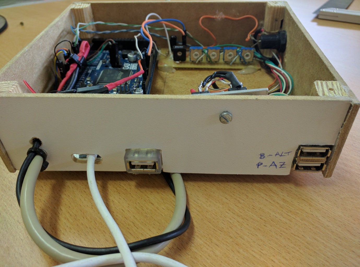


It's desirable if you build a box to place the all the components, including the Arduino.
The box I made will never win a beauty contest, but it's big just enough to fit everything I need, it's light and portable and the most important, hold tight and protects the electronics.
I used 5 pieces of 3mm plywood glued together to make a 16x14x5 (cm) box, as you can check from the pictures above.
To reinforce the box, I glued some pieces of wood at the corners. The cover, as you can see, is made from a piece of acrylic. It's not mandatory to be transparent, but it should be removable. Just drill a hole at each corner to screwing it.
Drill some holes for passing the cables.
You can add a hook to hang the box in a convenient place or, like the in last image above, you can glue a piece of plywood with a hole that you can use to hang the box using an existing bolt from the mount.
NOTE: Because I also use this box for many other purposes, there are some extra cables going around. Please ignore them!
Step 8: Electronics - Make the Interface and Wire It Up


After you build the box, just place the Arduino and secure it with some hot glue or even some small screws.
Connect the USB cable (I'm using the programming port on Arduino).
Building the interface:
We need to build the hardware interface for 2 reasons:
- Adapt the voltage level from the encoder (minimum voltage = 5V) to Arduino DUE (3.3V);
- Add a pull-up resistor (it's needed because the output from the encoders is a open collector).
Above, you can find the shcematics that I used for each encoder's channel. You will need to build 4 like those.
It´s a very simple interface, where a 470 ohm resistor is used to pull-up the encoder's output and a 10K trimmer is used just as a voltage divider. The trimmer's center pin is then connected to the Arduino's input pins.
I used the following configuration:
- encoder 1, channel A - connected to pin 2
- encoder 1, channel B - connected to pin 3
- encoder 2, channel A - connected to pin 5
- encoder 2, channel B - connected to pin 4
WARNING: Be sure, before you connect the encoders to Arduino, that you adjust the trimmers to output exactly 3,3V. It's very important that you not exceed 3.3V, otherwise you will damage the Arduino.
To do that safely, connect the red wire from the encoders to the +5V Arduino pin and the black wire to ground. Adjust all the trimmers until you read 3.3V at the middle pin. You might have to slightly rotate the encoder to find the "ON" position at each channel.
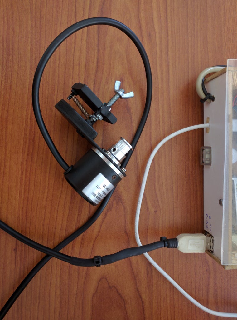
To became more portable, instead soldering directly the encoder wires to the PCB, I added USB connectors that I took from 2 USB cables. Solder the female ends to your PCB and the male ends to your encoders.
By doing this, just be sure you won't swap any wire - following the colors would help you a lot!
As I told before, I'm using this Arduino for other purposes, so ignore all the extra wires and components you see from the pictures above - you will not need them!
Step 9: Important Steps Before Making the Code
To become a little more "instructive", I feel that I owe you, at least, a simple explanation about the way I programmed the Arduino and the techniques I used to make (almost) any telescope "speak" with Stellarium.
Despite of involving maths, trigonometry, programming and some signal processing, don't worry, I will try not to be too extensive!
Knowing the encoders:
In a very simple way, one encoder (angle encoder or position encoder) is a device (sensor) that can read, and therefore, transmit a position or an angle.
There are a lot of types of encoders. For this specific purpose, I have chosen the incremental ones. Despite being not so easy to integrate with Arduino (programmed in C), these encoders are reliable, cheap (at least the ones I bought..!), easy to find and, the most important, they can be very accurate while having high resolution.
The major problem using this type of encoders is that they never give you their position (angle)... instead, they give you pulses...strange? So, how can we know the angle? Here's a very little explanation:
- There are two channels at each encoder (channel A and B);
- Each channel can switch between ON and OFF (0 or 1) as you turn the encoder. That is a pulse!
- The 2 channels are not in phase. There is a 90º lag between them. That is called a quadrature signal;
- By using quadrature signals, we can know the direction of movement (if one channel is leading or lagging the other);
- It's also possible multiply the resolution by 2 or by 4 (quadrature proprieties);
- We can calculate the position by counting the number of pulses (CW and CCW);
The technique: To avoid loosing pulses (because the code takes some time to run...), I used some special pins and functions on Arduino: Interrupts. So, each time that one of this pins changes his state (meaning the encoder has moved), this special pin (through the interrupt) activate a special piece of code (ISP - Interrupt Service Routine). Here you can read some extra information about using interrupts on Arduino.
This technique makes it possible to define a "time sensitive" section of code, and that was what I did to count all the pulses, with no exception.
Communication with Stellarium
Nothing too difficult here!
The Stellarium plugin works just fine with the LX200 protocol. I think it's an old and outdated protocol, but is simple to use and, for this end, works just fine.
While connected to Arduino, periodically Stellarium sends 2 strings: ":GR#" - ready to receive RA and ":GD#" - to receive DEC. The code checks this strings and then sends, to the serial port, the corresponding string with the current right ascension (RA) and declination (DEC).
Coordinate system conversion
Now, the complicated part... Every dobsonian (or altazimuth) mount uses two axis (altitude and azimuth, as you should already know!) to create a coordinate system. This system it's very intuitive and easy to use because is related with your quotidian life (go up/down and right/left...).
But, this coordinate system is very poor if you are talking of astronomy. That happens that the sky is "alive" and seems to move around continually. Actually, all the stars describes a circumference centered at the pole star. They rotate 360º in about 24H (15º per hour).
As you can imagine, if at certain moment you are pointing to one object using a certain coordinate, after a few minutes, you need to recalibrate your coordinates because the object has moved, so, altazimuth coordinates are time dependent. They also are location dependent, as you can imagine!
So, to prevent using a coordinate system that changes every single second, the astronomers have found a very ingenious way to determine the sky coordinates - the equatorial coordinate system.
Because Stellarium, through the LX200 protocol, only can read equatorial coordinates, I had to find a way to convert the readings from the telescope (altazimuth) to the equatorial coordinate system. That operation is a little bit complex because involves spherical trigonometry and some time concepts (Local Sideral Time - LST).
Everything about this conversion is done, once in a computing cycle, using the function "AZ_to EQ()".
To learn more about coordinate systems, positional astronomy or LST, you can go here, here and here...
Welcome to my world!
Step 10: Install Arduino and Load the Code!


Hope you are already familiar with arduino, but if you aren't, please, don't worry - there is a lot of information you can get on-line. Nevertheless, I will guide you how to start from scratch!
It's quite easy to load the code into your Arduino. If you don't have the arduino IDE, you can download it freely from here. I'm using the version 1.6.8, but others should work as well (just in case, try not to use some older versions). Just download and install into your computer.
Be sure you have installed the DUE drivers (SAM boards, 32 bits) - check images above.
Connect the USB cable to your computer and open the code (see attachments). Be sure the code files (NF_v1.ino and config.h) are inside a folder with the same name ("NF_v1").
Select, under the "tools" tab, the board (Arduino DUE - Programming port) and the port that you are using. Note that the port (port 4 in my case) can vary from computer to computer. It will be the serial port that your computer associates with Arduino.
After everything is set up, click to upload the code (Sketch > Upload).
A "Done uploading" message will show up, after a few moments, at the bottom of the screen. That means your code is compiled and uploaded into your Arduino.
After that, you are ready to go!

Step 11: Install and Config Stellarium


You are almost there!
If you don´t have Stellarium installed into your computer, it's time to do so!
You can download it for free, from the Stellarium homepage.
Stellarium is a really nice software for astronomy. It features a user friendly environment and, if you choose a recent version (version 0.13.1 or ), should already integrate the Telescope plugin, so, the only thing you need to do is activate it!
Go to the configuration window and choose the "plugins" tab. Check the box to activate the plugin. The next time you open Stellarium, you should have a new tool at the bottom's bar (see pictures above).
Click on the "telescope tool" and then select "telescope configuration".
It will open a new window. At this window, choose "add telescope".
To configure your telescope, follow the images above. You only need to this one time!
One thing that is important to do: Set up your location, otherwise, all the coordinates will be wrong..
So, just click, at the left side of your screen, the location manager and add your location (I mean, your observation site location...!).
Among other things, you can customize some visualization features. Make a tour and learn how to use it!
For this purpose, it's desirable that you enable some features at the "view" and "configuration" tabs, as you can see from the pictures above.
Finally, you are ready to connect your telescope to Stellarium!
Go to the next step to learn how to do it!
Step 12: Test and Run!


Now you are only a few steps from your reward!
Make sure you have everything in place (both electrical and mechanical) and run your telescope by opening the telescope's plugin. Click "configure telescope". A new window will show up and the only thing you need to do it's click "Start" and... voilá!
Wait a few seconds (10 seconds or so..) and a new object ( _Hello_ ) will appear somewhere at the Stellarium's sky. It will have the same name you gave before...! Move around and you will find it!
Perform the movement test:
Move your telescope around and up/down. You should see the object moving accordingly at Stellarium.
Do you see it? GOOD WORK!
Troubleshooting: If your object tends to move at the wrong direction (azimuth or altitude), that means your encoder channels (respectively, azimuth or altitude) are reversed. Correct them by switching the corresponding wires at Arduino or, simply, by changing the the code and load it again (see image). Please note that the Encoder 1 is the Altitude encoder and the Encoder 2 is the azimuth encoder. Use the "config.h" file to make your changes.
Set up your encoders count
Arduino must have configured how many pulses your encoders give by turn. So, using the "config.h" file, set how many pulses you have by turn and then multiply by 4. In my case, I have a 600 pulses encoder and a mechanical gear ratio of 15 times. That means I will have 9000 pulses by turn. Multiplying this number by 4, the number I wrote was 36000, as you can see from the example above. This will be the overall resolution, equivalent to an amazing 36 seconds of arc (1296000/36000). Comparatively, a full moon have about 30 minutes of arc wide (0,5º).
Align your telescope:
To keep maximum accuracy, the telescope mount should be perfectly leveled (use a bubble level).
By default, the telescope should be aligned to north (0º azimuth) and leveled horizontally (0º altitude) before connecting to Stellarium. You can do this easily by pointing the telescope to the pole star (0º north aprox.) and then move down until it's horizontal (use a bubble level...!).
Set up location and time:
Now, if you connect your telescope to stellarium, you will probably see that your telescope is not pointed to north as it should. Well don't worry... that's because your location and local sideral time (LST) are not the correct ones!
If you remember from a few steps ago, we should have both our local sideral time (LST) and location calibrated. To do that, just open the code using Arduino IDE and edit (using the tab "config.h") your current location and the right ascension (AR), as well the hour angle (H) of the pole star (at the moment you connect to Stellarium). You only need to set up you latitude. Longitude will be calculated through AR and H.
To set up your location and time, please follow the steps I described in the images above.
Load the code again and reconnect to Stellarium. The code will do the rest of the work!
ONE FINAL NOTE:
Never, but never point your telescope to the sun! It can cause you irreversible blindness.
Finally, you can point your telescope to whatever you want, using Stellarium to guide you!
Hope you enjoy it, as much as I do!

Participated in the
Space Contest 2016


