

Introduction: DIY Interactive LED Coffee Table


In this Instructable I’m going to show you how I made an interactive LED coffee table step by step.
I decided to make a simple, yet modern design, and focused more on its features.
This amazing table creates amazing ambiance in my living room.
How does it work?
It is actually controlled through a custom-made Android application, so you can change both the reactive and the background color using your Smartphone, and also you can control the brightness.
I used an MDF for the upper part, a pine for the frame and the legs below, and a glass on the top. The inside consists of an Arduino Mega board, a Bluetooth device, Addressable LEDs, IR proximity sensors and a bunch of wires.
Here you can see the process of building, wiring and joining all the parts together with detailed instructions. Don't forget to watch the video to experience the entire process of this build.
Here's my website article: https://creativityhero.com/diy-projects/diy-interactive-led-coffee-table/
Materials:
- Arduino Mega Board http://amzn.to/2DpTRXf
- Bluetooth Module http://amzn.to/2DpLHhB
- Addressable LED Strip Light WS2812B http://amzn.to/2Fz0DL4
- Infrared proximity sensors http://amzn.to/2FwUONZ
- Wood glue http://amzn.to/2fshgMw
- Wood filler http://amzn.to/2B8kJ0b
- Oil based paint http://amzn.to/2zkWdGC
- Rosewood stain http://amzn.to/2CTP2oq
Tools:
- Circular saw http://amzn.to/2fRs8nD
- Random orbit sander http://amzn.to/2zk6sel
- Cordless drill http://amzn.to/2frP8MD
- 90 degree angle clamps http://amzn.to/2CUEbKx
- Band clamp http://amzn.to/2ECsTLz
- Paint roller kit http://amzn.to/2Dqhpvc
- Pocket hole jig http://amzn.to/2Dcloh0
- Soldering iron http://amzn.to/2FvLdqT
- Multimeter http://amzn.to/2r0zCwF
- Wire strippers http://amzn.to/2qYPdwG
- Glue gun http://amzn.to/2CXk9iH
Step 1: Cutting All the Pieces to Size.


All the pieces needed for this build I cut on my table saw. The box is made out of MDF: 18 mm thick for the sides, and 8 mm thick for the bottom and the inner parts.
The majority of the cuts I made using my table saw fence. For the larger pieces I wasn’t able to use the fence because it is pretty wide, so I secured a scrap wood onto the workbench and used it as a guide.
To create a grid inside the box, I’m cutting 12 pieces of MDF, 4 cm wide.
The frame and the legs below the box are made out of pine board. The board was warped, so I needed to make a lot of cuts and adjustments on the table saw and the fence to flatten it and to get nice and smooth strips out of it.
Making repeated cuts is extremely easy with a stop block. I mounted my homemade stop block, and made most of the repeated cuts. Besides the existing stop block, I made another one by clamping a scrap of wood onto the fence. This way I was able to cut much longer pieces.
To make the grid that I mentioned earlier, first I need to make dadoes onto each piece. Those dadoes will help me lock the pieces together and make a flawless, squared grid.
One of the easiest and fastest methods to make such dadoes is the following: mark all the points for the dadoes on one piece, wrap all the pieces together with a masking tape, adjust the height of the blade, and start cutting.
Step 2: Sanding.

Once I’m done with all the cuts, I can move on to sanding.
I began with 80 grit sandpaper and then continued with 120 grit, until everything was nice and smooth.
Step 3: Assembling the Box.


I started the assembling process with the box. I applied a wood glue on the corners of the MDF pieces, and clamped them together with some corner clamps and a bend clamp.
To secure the sides well, I screwed a small piece of wood in each corner of the box.
Then I moved on to the bottom. I applied a generous amount of wood glue and a bunch of screws to firmly attach it.
In order to avoid any gaps, I applied a wood filler and left it to dry.
While it was drying, I made two holes into the bottom, one 6 mm wide for the main power cord, and the other wide enough to fit the switch snugly.
When I inserted the smaller MDF board inside the box I realized it was warped in the middle because it is pretty long, so to fix it I additionally secured two more small pieces of wood for better support.
Also, I added extra 8 mm height onto those pieces out of MDF, so that when I finally place the glass on the top of the table, it will be flush with the sides.
Step 4: Painting the Box.


I removed the extra wood filler with a fine grit sandpaper and wiped the dust off of the surface with a wet rag to prepare it for painting.
I need to paint just a little of the inner part of the table, so I apply a masking tape on the sides to get clean and straight paint lines.
After that I started painting. I applied an oil based primer using a combination of a roller for the large surfaces, and a brush for the corners.
Then, I left it to dry. Once it was completely dry I sanded it with my random orbit sander.
Now I can apply paint. I decided to use white oil based paint, because it will match my interior. I left it to dry and moved on to the other parts of the table.
All the pieces that I’ll use for the grid I painted white as well.
Step 5: Assembling the Frame and the Legs.


This pieces I’ll join together with pocket hole screws. The pocked hole jig that I have is very useful tool for making pocket holes.
The width of the strips doesn’t allow me to make two holes on each side, but later I will mount corner brackets if I need additional support for the legs.
To make a stronger connection I’m applying a wood glue, and then I’m attaching the screws on the top of the frame, because I don’t want the holes to be visible. Here also I’m applying a wood filler to fill in the gaps.
Step 6: Staining the Bottom of the Table.


After the wood filler was dry, I sanded the excess and prepared this part of the table for staining.
Speaking of the stain, I went with a rosewood stain to get a perfect contrast with the white paint.
Step 7: Assembling All the Parts of the Table.

Now I can finally assemble the entire table.
I placed the top onto the bottom, secured it with some clamps, and used a lot of countersunk screws to make a better connection.
Step 8: Making Holes Into the MDF Board for All the Electronic Parts.
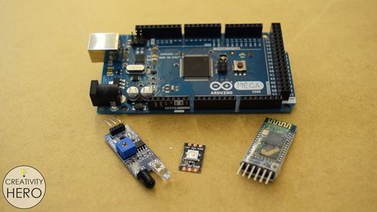


The electronic parts needed for this project are: Addressable LEDs, Infrared proximity sensors, an Arduino Mega board, a Bluetooth module, 5V power supply and a bunch of wires. All of this will be attached onto the board.
This board will be divided into 45 squares. I’m using a template to drill 3 holes into those squares. I’ll fit the electronic parts with some wires into the holes.
Step 9: Cutting and Preparing the LEDs.


Then, I sniped 45 individual LEDs.
I’m cutting 5 cm long pieces of black and red wire and stripping off the insulation of their ends. With these wires I’ll connect the LEDs and the proximity sensors.
I’m repeating this step with a green wire.
Then, I’m soldering the wires. On the Ground and the 5V pad I’m soldering the red and the black wire, and on the Data IN pad I’m soldering the green one.
Step 10: Adjusting the IR Proximity Sensors.


First, I removed the IR transmitter from the sensor.
The sensor won’t detect a glass on the table top in a normal position, because the glass won’t reflect the Infrared light.
The transmitter and the receiver need to be positioned at an angle so that the light can be reflected to the receiver on the other side.
So, I’m soldering the transmitter back on the sensor, but this time with 4 cm long single core wires from an Ethernet cable. These wires can be easily bent and stay in the desired position.
On the other side of the sensor I’m soldering the black and the red wire to the Ground and 5V pin, and a longer grey wire to the Output pin which will actually connect the sensor to the Arduino board.
To make that connection possible I need to solder pin headers onto the ends of the longer wires and insulate them with a shrink tube and a lighter, that way they can be easily positioned into the Arduino board.
Step 11: Inserting the LEDs and the IR Proximity Sensors.


The LEDs need to be inserted into the holes that I previously drilled and stuck onto the board.
Then I connected them by soldering the green wire in the middle of each LED, or the Data OUT pad of the previous LED to the Data IN pad of the next LED.
Once I’m done with this step, I’ll basically do the same with the proximity sensors. This time I’ll hot glue them next to the LEDs.
All grey wires will be inserted into the Arduino board which will be positioned in the middle of the back side of the board. They have different dimensions, depending on their distance from the Arduino board. You can find the dimensions that I used on the website article.
The transmitter and the receiver need to be positioned facing up, so I’m making some adjustments here carefully.
Step 12: Soldering the Wires and Inserting Them Into the Arduino Board.


I’ll start with attaching copper wires along with the length of the board with hot glue. They will be used as power rails for the LEDs and the proximity sensors. On the first rail I’ll solder all red wires, and on the other line all black wires (positive and negative).
To be able to solder, I need to remove the insulation off of the copper wires by sanding it.
At the end I connected all the positive and all the negative lines, and added two more wires which will go into the power supply.
I soldered 330 ohms resistor between the first LED and the Arduino, to reduce the noise on that line.
All the wires along with the Bluetooth module are ready to be inserted into the Arduino board.
The Circuit Schematic
This circuit schematic will help you see how I connected everything together. For more details on how to use the Arduino in combination with these addressable LEDs and the Bluetooth device check Dejan Nedelkovski YouTube Channel, and his website howtomechatronics.com.
He made a tutorial on how everything works, including the source code of the program and the custom-built Android application.
Step 13: Inserting the Power Supply.


Before doing anything else I made a continuity test on the circuit, using a multimeter. The multimeter didn’t beep which means my connections are all good, and I can move on to mounting the power supply on the bottom of the table. I raised it up a little by gluing two pieces of MDF, so that it could get a better airflow.
Then I inserted the main power cord and the switch into the holes and connected them to the power supply. I wired a plug on the end of the cord. After that I brought the MDF panel and connected the last two wires into the power supply.
Step 14: Programming the Arduino Board.

Now I’m ready to program the Arduino. The code is fairly simple, it just reads the proximity sensors, so if an object is detected it lights up the particular LED.
I use a custom-built Android application for the color and brightness control. The data that comes from the Smartphone is received through The Arduino Bluetooth module.
You can find detailed explanation on how this code works on Dejan’s article.
Step 15: Some Final Adjustments.


Once I uploaded the code, I placed the panel inside
the table. I noticed here that the power indication LED of the proximity sensors would interfere with the main LED light, so I covered them with an electrical tape.
To make the grid I just need to lock all the parts together, which fit pretty snugly.
Finally, I can put the matte glass on the top of the table and turn the switch on to see how it works.
One of the LEDs doesn’t turn on when I place a glass on top of it, and I needed to adjust the angle of the transmitter so that it would be able to reflect the light to the receiver.
Step 16: Final Result


Now I’m finally done with this interactive coffee table. It turned out wonderful.
I hope you enjoyed this Instructable. Don’t forget to check my video and subscribe to my YouTube channel.
YouTube: https://www.youtube.com/CreativityHero
Website: https://creativityhero.com/
Facebook: https://www.facebook.com/CreativityHero/
Instagram: https://www.instagram.com/creativity.hero/
Pinterest: https://www.pinterest.com/creativityhero/

Second Prize in the
LED Contest 2017

Participated in the
Arduino Contest 2017

Participated in the
Epilog Challenge 9


