

Introduction: Desktop DIY CNC Router - Arduino Based

Goal for this machine :
- Arduino based 3-Axis machine
- Cutting material : wood , plastic , aluminum
- Repeatibility < +/- 0.1 mm
- Cost < $750
- Travel : X-Axis 360 mm ... Y-Axis 500 mm ... Z-Axis 45 mm
This goal in mind, fixed gantry design was decided for improved rigidity and design simplicity.
Frame :
Aluminum parts laser cut from 6mm plate and V slot aluminum extrusion bolted together.,
Linear Guide :
Induction hardened chromium plated linear guide rods and linear bearings LMK20UU for X and Y-Axis and LMK12UU for Z-Axis.
Linear Drive :
T8 OD 8mm lead screws pitch 2mm lead 2mm with Pillow Block End Bearings and Anti Backlash Nut Blocks.
Drive Motors and Controllers :
Nema 23 381 oz-in 3.5A KL23H2100-35-4B stepper motors for X and Y-Axis and Nema 23 57HS22 stepper motor for Z_Axis. TB 6600 step motor drivers.
Spindle :
500 W DC air cooled spindle.
500 W 48V 10.4A power supply.
PWM speed governer.
Step 1: Parts Laser Cut From 6mm Aluminum Plate

Attachments

Step 2: Frame
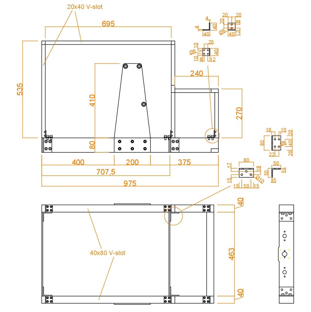

Aluminum plate part no 1 is bolted to V-slot 40x80 extrusion using 4 angle pieces L50x50x5 ...80mm long and T-bolts. V-slot 20x40 pieces are bolted to 40x80's using 6 angle pieces L40x40x4 ... 40mm long and again using T-bolts. 20x40 corners are fixed to each other using concealed fixers. The top and stepped front side is fitted with 4mm transparent acrilic plate. Power supply units, controllers, speed governer and other electronics are mounted to these plates.
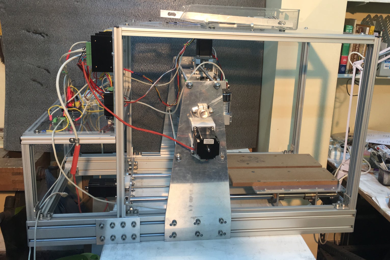
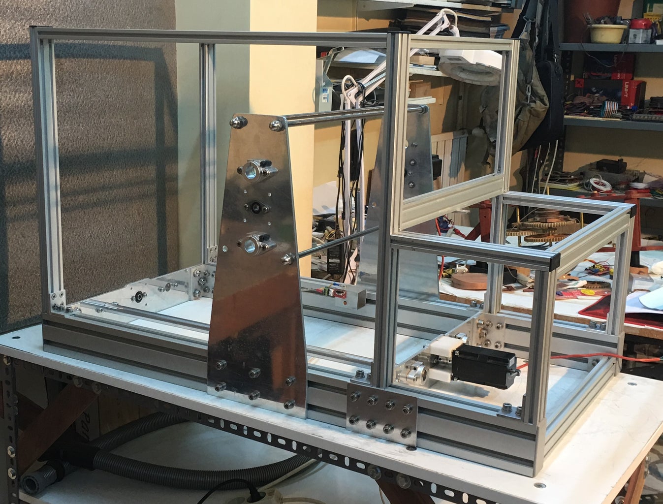
Step 3: Pictures of Completed Frame


Step 4: Y-Axis Assembly


Two angle sections L40x40x4...180mm long are drilled as indicated and used to bolt together work table part no5 and part no 6. Four linear bearings LMK20 are fixed to plate no 6. The linear guide end supports SHF20 and lead screw end bearings KFL08 are fixed to the outside of plate no 6.
Step 5: Anti Backlash Nut Block


An anti backlash nut block is fixed to a L50x50x5...100mm long angle piece and this piece is fixed to the inside of part no 6 using the center 3 holes.
Step 6: Pictures of Completed Y-Axis Assembly


The completed Y-Axis assembly is placed inside the frame and linear guide rods are placed through one of the end supports first then linear bearings and the second end support at the otrher end. Lastly the lead screw is placed. After assembling make sure that you can move the worktable easily by turning the lead screw by hand. If there is excessive firiction reassemble and realign.
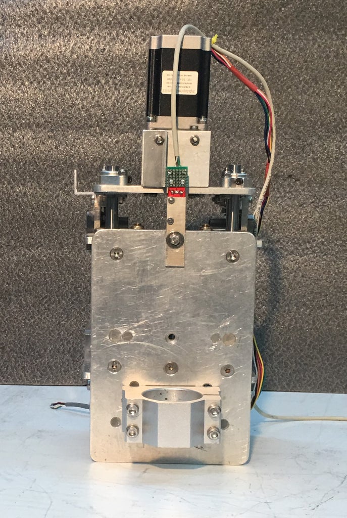
Step 7: X-Axis Assembly


The laser cut parts 3 and 4 are bolted together using four 70 mm long aluminum square sections 15x15mm. One leg of 50x50 aluminum angle is cut to 25mm making it L50x25x5...70mm long. This piece is drilled as shown and bolted to piece no 3. to it the anti backlash block is fixed. Because of the axial load the Z-Axis lead screw is need to be supported by a thrust bearing. The thrust bearing and lead screw housing are custom manufactured and fitted to the underside of part no 4 together with the lead screw bearing.
Step 8: Z-Axis Assembly

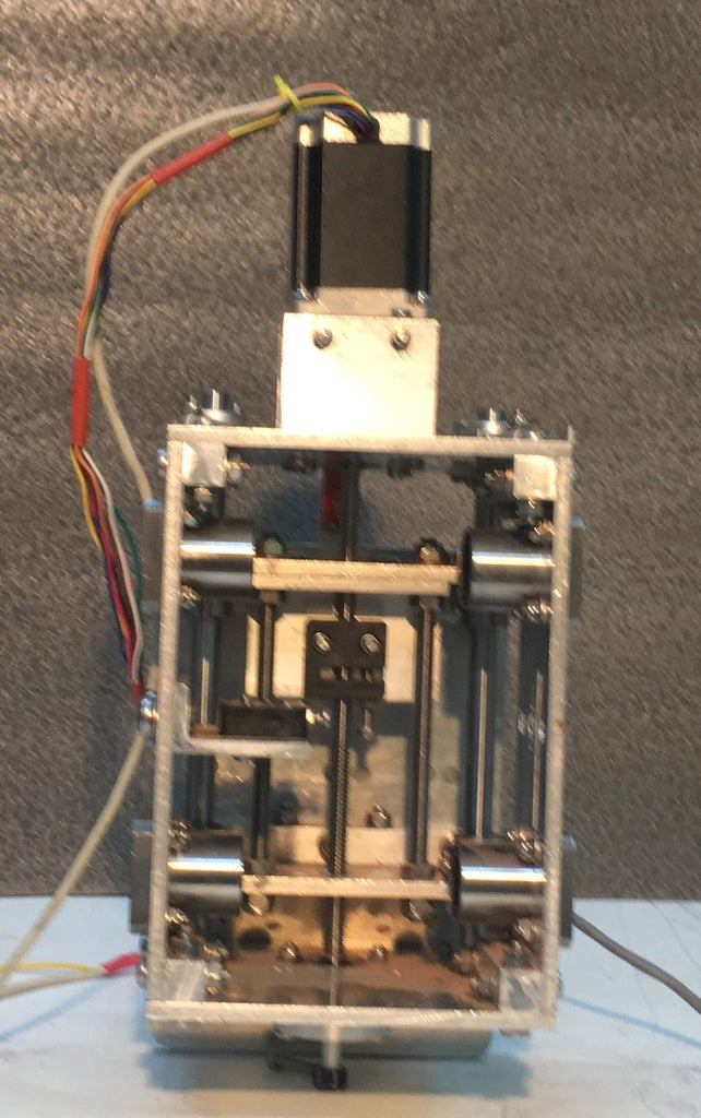
Laser cut parts 7 and 8 are bolted together using two 135mm long aluminum square sections. One L50x28.5x5...80mm long is cut from 50x50mm aluminum angle, drilled as shown and bolted to part 7.To it the anti backlash block is fixed.Two 150mm long 8mm screws are fiited between top and bottom no 7 pieces for rigidity.
Step 9: Putting X and Y-Axis Assemblies Together

12mm linear guide rods are placed through one of the end supports first then linear bearings and the second end support at the otrher end. Lastly the lead screw is placed. After assembling again make sure that you can move the Z-Axis assembly easily by turning the lead screw by hand. If there is excessive firiction reassemble and realign.
Step 10: Stepper Motors
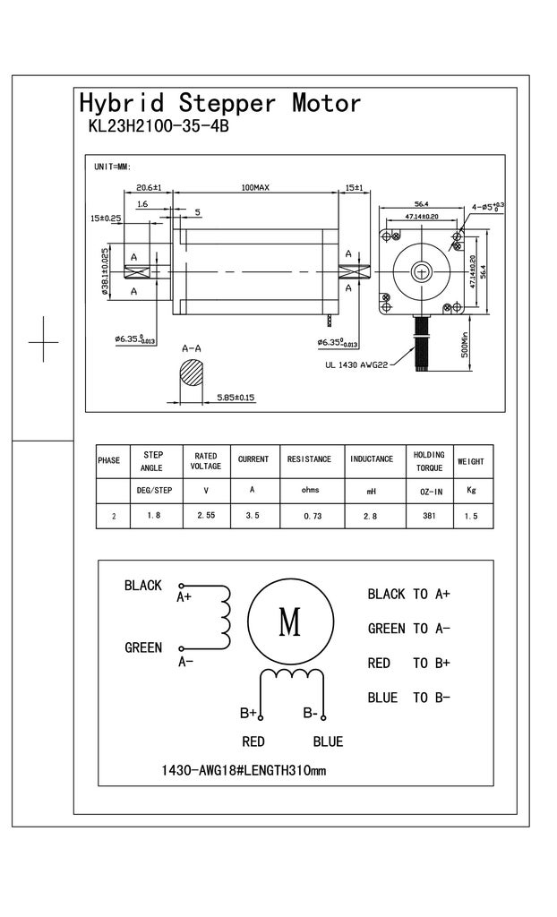
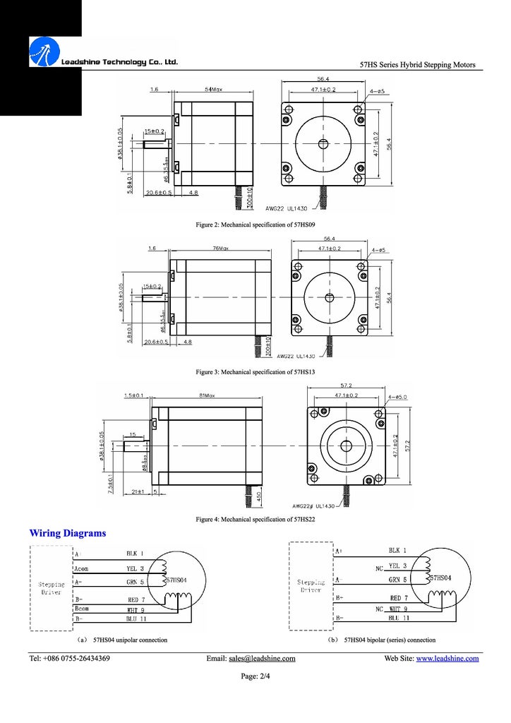


Nema 23 381 oz-in 3.5A KL23H2100-35-4B stepper motors are used for X and Y-Axis. For Z-Axis Nema 23 57HS22. Plastic block spacers are used to dampen vibration. Steppers are connected to lead screws via flexible couplers. TB6600 Drivers are used for all 3 motors.
Step 11: Power Source for Steppers

Step 12: Limit Switches

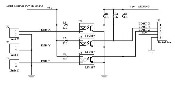

One Makerbot type mechanical endstop is used for each axis For improved noise filtering they are wired using shielded cables and optocouplers. The circuit is wired on a 5x7cm single side PCB.
Step 13: Pictures of the Optocoupler PCB


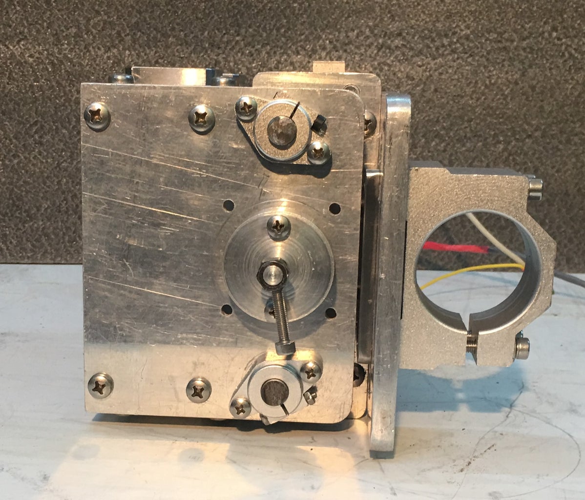
Step 14: Spindle


Spindle : Air cooled DC 500W 12 000 rpm with PWM Speed Governer
Power Source : 48V 10.4A 500 W
Step 15: Arduino and GRBL

Some Basics :
Hardware : Arduino Uno R3 with CNC Shield V3.00
Software : GRBL , UGS
GRBL is opensource software that runs on an Arduino Uno that takes G-Code coımmands via serial and turns the commands inbto motor signals.
Universal G-Code Sender is a Java based,cross platform G-Code sender compatible with GRBL and TinyG/g2core. Use it to run a GRBL or TinyG/g2core controlled CNC machine.
GRBL V0.9 - Arduino Z-limit and spindle enable pins are swapped.
See below :
http://github.com/grbl/grbl/wiki/Connecting-GRBL
TB6600 Wiring Diagram with Ardaino CNC shield is given in the picture above.
Configuring GRBL V0.9 :


