

Introduction: ESP8266 Wifi Switch


In this tutorial I'm going to show you how I made a wifi switch from scratch (or almost) using the well known ESP8266.
The idea is the following: I want to be able to turn on/off several lights or devices connected to the power supply from my phone. I don't want the switch to rely on a battery. The switch will need to connect to 1 of 2 preprogrammed wifi. I want to be able to make groups of switch, and turn them all on/off by the push of 1 button. I want to be able to turn it on/off at a specific day and time using a timer. And I don't want to pay more than a total of $30 per switch, since I want to make a dozen of them.
The components won't be put on a breadboard, but rather soldered on a PCB, in order to make the switch as small as possible, and to be able to handle the high power.
The interface between the switch and the phone will be managed by the Blynk app.
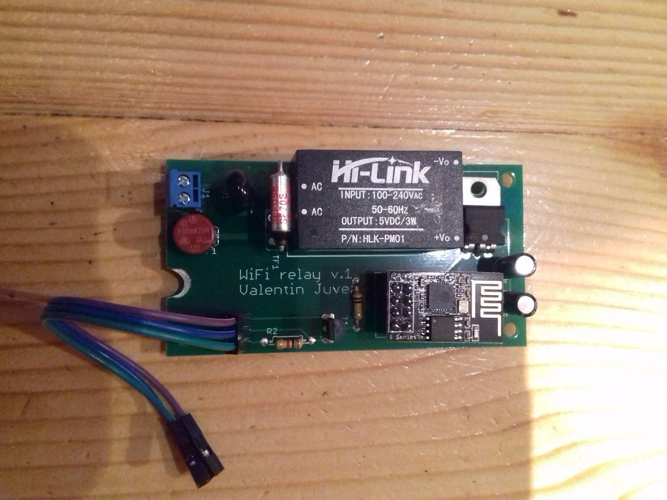
The end result is shown above: you simply connect the male plug to the wall socket, your device that you want to control to the female plug, and voilà! You can control it with your phone.
Since this is one of my first projects of this kind, I made a few mistakes that I realized afterwards. I'll note the improvements that can be made in this tutorial, along with the version 2 of the PCB. Please note that I haven't printed the version 2, so I have no idea if it actually works.
I'd like to point that I'm new to this field, so I might not use the correct terms: be gentle!
Step 1: Scheme and Components


I used the 2 following well-explained tutorials before doing this project:
- WiFi / Internet Controlled Relays using ESP8266 (This one uses a power supply and an adapter to power the switch)
- ESP8266 WiFi relay switch (Arduino IDE) (Uses the EasyIoT web interface instead of the Blynk app in my case)
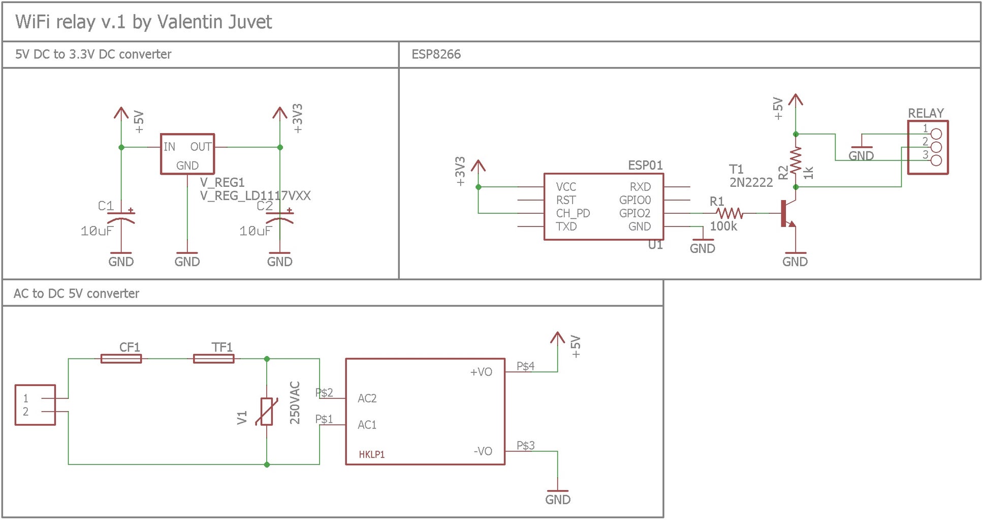
Ok so I decided to use the ESP8266-01 for its cheap price and its small size. It has 2 digital outputs, we're only going to use 1 of them (GPIO2):
http://www.ebay.ch/itm/Orig-AI-Thinker-ESP8266-ESP...
For the relay, I've used a single relay board:
http://www.ebay.ch/itm/5V-1-Channel-Relay-Board-Mo...
The ESP8266 uses 3.3V, and the relay needs a 5V input to work. In order to convert the power to 5V, I've used the HLK-PM01:
http://www.ebay.ch/itm/HLK-PM01-AC-DC-220V-to-5V-S...
It takes 100 - 240VAC and converts it to 5VDC. In order to protect it from overheat, high voltage and high current I've used a 73°C thermal fuse, a 250VAC varistance and a 315mA fuse:
- http://www.ebay.ch/itm/Thermal-Fuse-Cutoff-Sefuse-...
- http://www.distrelec.ch/fr/varistance-320-panasoni...
- http://www.mouser.ch/ProductDetail/Littelfuse/3700...
Then to convert 5VDC to 3.3VDC I used the voltage regulator LD1117V33:
http://www.distrelec.ch/fr/regulateur-de-tension-l...
On top of that I've used the following parts:
- A screw terminal to connect the power cable: https://www.adafruit.com/products/724
- NPN Bipolar Transistors (PN2222): https://www.adafruit.com/products/756
- Female/Male 'Extension' Jumper Wires - 20 x 3" to connect the relay: https://www.adafruit.com/products/1953
- 1k and 100k resistors: https://www.sparkfun.com/products/10969
- 10uF capacitors: http://www.distrelec.ch/de/aluminium-elektrolytko...
The scheme and the board were made using the free version of Eagle. 2 layers were used for the board, though only 1 could have been used. The board was pannelized and 20 copies were printed for about $100 by Gold Phoenix.
If the ESP8266 was soldered on the board, it would need to be desoldered to reprogram it. So instead I soldered 2 rows of female headers and plugged the ESP8266 on it. (36-pin 0.1" Female header)
- Improvement 1: The ESP8266 plugged in the headers is quite elevated on the board, this means the 2 capacitors could have been turned 90° and bent under the ESP8266 to gain some room. This has been corrected in version2.
- Improvement 2: The 315mA fuse drawn on the board is square-shaped, but I could only find round-shaped fuse for that current (the pitch is the same so it's fine). Corrected on version2.
- Improvement 3: The 3.5mm screw terminal chosen are really too small to put the power cable in, especially that I needed to put 2 wires in each hole to connect the relay in parallel. A bigger, 5mm screw terminal has been chosen for version 2 (https://www.sparkfun.com/products/8432).
Step 2: Assembling


After burning 2 thermal fuses when soldering them, I found the following trick to solder the next ones succesfully:
- Place the thermal fuse first on the board, before any other component
- Bend it so it will be placed close to the HLK-PM01
- Turn the board over and place it on a cup of water. The body of the fuse has to be submerged so the temperature increase will be slowed down, but the board should not touch the water, otherwise the soldering would be impossible.
- Solder the fuse by being carefull not to heat the part too much or too long.
The other components presented no particular problem.
The ESP8266 is then programmed using Arduino IDE (see next step for the program). The scheme to program it is the one presented in this tutorial. An FT232RL USB to TTL Converter Module was used: http://www.ebay.com/itm/302036807558
Before uploading, the ESP has to reset with the GPIO0 to the ground.
The ESP8266 is then plugged on the board, and the relay plugged in the jumper wires.
The power lines were connected according to the scheme and pictures above.
The whole thing was put in a plastic case with a hole on each side, and then a male and female plug were connected.
Step 3: Blynk App and Programming


The Blynk interface
My Blynk interface has 4 tabs:
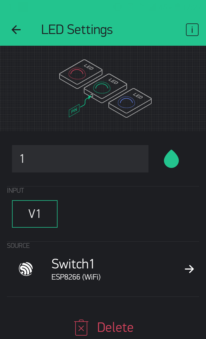
- The 1st tab controls switch 1 to 10 individually using buttons. The buttons send a high(1) or low(0) value to the virtual pin V0. Next to each button, an led is used as a feedback. It reads the virtual pin V1. If the relay is closed, V1 is high, and the led lights up.
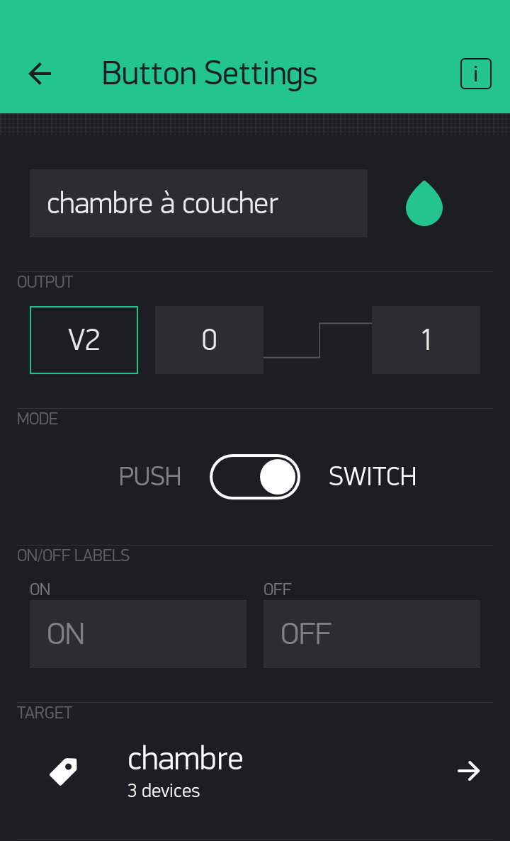
- The 2nd tab also controls switch 1 to 10 but by groups: the first button controls all the lights of bedroom1, the second one controls all the lights of bedroom2, etc...). These buttons use the virtual pin V2. For this, tags had to be set to group several switches on the same button.
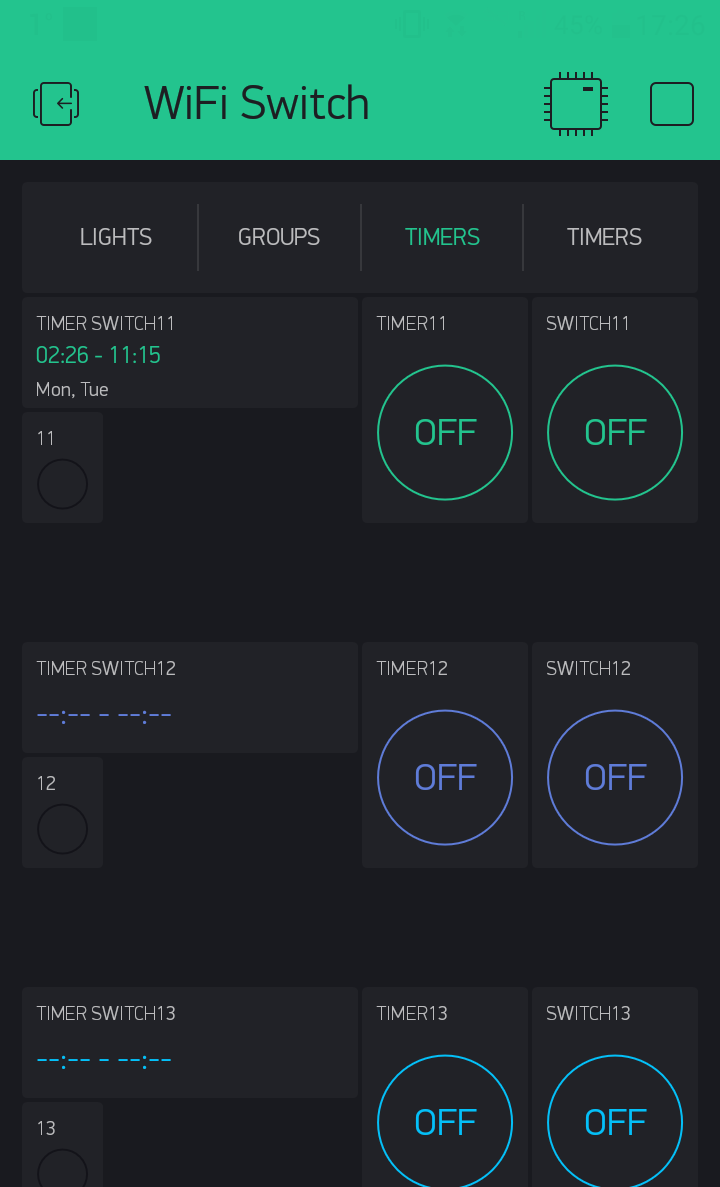
- The 3rd and 4th tabs control switch 11 to 15 individually. They can be controlled directly with a button via virtual pin V0, or by a timer. The start/stop time and weekday are set using the Time Input widget via virtual pin V3. The timer functionality can be turned on/off using the last button, via V4. The ESP8266 knows the date and time by Blynk, through the RTC widget.
Note1: Unchecking all weekdays in the time input widget does not turn the timer off. It actually turns it on everyday!
Note2: In order to use the RTC widget with the ESP8266, you need to have the latest app version, and at least library version 0.4.4 (at the time of writing, version 0.4.4 is not available yet in the arduino IDE and you need to manually download it here).
The software
The code I wrote is presented in the GitHub repository below. I think it should be well-enough commented to understand it.
Step 4: Improvements
Some improvements can be brought to this project and are corrected in the version 2 of the GitHub repository.
- The rectangular TE5 amp fuse is replaced by a round TR5
- The 3.5mm screw terminal is replaced by a 5mm screw terminal. Part: https://www.sparkfun.com/products/8432
- Capacitors are turned 90° so they can be bent under the ESP, and ESP moved up
- More room is reserved for the relay
Once again, I haven't tried version2, and I don't plan to print it since version 1 works. So please double-check version 2 if you want to use it. And let me know if you find any mistake.
If you want to build this project or part of this project, do it at your own risk. I do not guarantee its functionality or its safety. The project is licensed under MIT License. This means you can use it for commercial purposes, distribute it or modify it, only include a copy of the license and copyright notice with it.
If you have any other suggestion, or feedback, please let me know! Looking forward to have your input.


![Tim's Mechanical Spider Leg [LU9685-20CU]](https://content.instructables.com/FFB/5R4I/LVKZ6G6R/FFB5R4ILVKZ6G6R.png?auto=webp&crop=1.2%3A1&frame=1&width=306)


